Subsections of Vehicle Specific
Mitsubishi EVO 4-8
Mitsubishi EVO 4-8 Plug-in ECU User Manual
1.0 Introduction
The Mitsubishi EVO 4-8 ECU is designed to be plugged into the OEM harness to allow for a true “Plug and Play” install. The system is based on the KV Series Motorsport ECU, so all the same features are available excluding any limitations based around the OEM connector system. An Expansion port is included giving access to unused Input channels. CAN Bus 1 is also available providing additional I/O expandability.
2.0 Plugin Features
General
- KV8 ECU based platform — Dual 100MHz processors, 32MB ECU logging memory, over 1000 logging channels, 1Hz to 500Hz logging rate
- Aluminium 6061 Grade CNC billet enclosure
- Compatible with all Emtron proven motorsport features (Launch Control, Rolling Launch, Anti-Lag, Traction Control)
- Upgradeable to run the Emtron fuel model through installation of a flex meter, fuel temperature and fuel pressure sensor
- Idle speed closed loop control using DBW with advanced Throttle Mass Flow (TMF) airflow calculations
- Knock control with high speed digital filtering for each cylinder using the OEM sensor with selectable centre frequency and bandwidth
- Pre-configured calibration file loaded providing a comprehensive tuning platform
- Input Expansion Capabilities through DTM connector: 3× User Analog Volt Inputs (Fuel Temperature, Fuel Pressure, Inlet Temperature), 1× User Digital Input (Flex Meter Input and switch inputs), 2× User Analog Inputs
- Emtune software for tuning and data analysis
Communications: CAN 2.0B Bus 1 (User CAN Bus for I/O expansion — Lambda, EGT); High Speed Ethernet 100Mbps for tuning software connection.
Operating Temperature: -30 to 85°C (-22 to 185°F)
Physical: Enclosure Size 160 × 162 × 38 mm, 890g
3.0 Installation
3.1 Expansion Port
The ECU’s input capabilities can be expanded using the expansion connection, which is a male DTM 12 Way. These additional inputs can be connected to any sensor, but the recommended sensors are indicated in brackets.
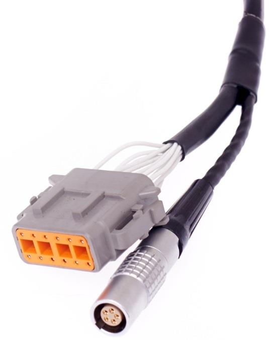
EVO 4-8 expansion port connector (DTM 12-way).
Table 3.0 — Expansion Port Pinout (DTM06-12SA)
| Pin | Function |
|---|---|
| 1 | Analog Sensor 0V Reference |
| 2 | 5V Vref2 Supply |
| 3 | AN 8 (e.g. Fuel Temp or Inlet Temp) |
| 4 | AN 11 (e.g. Fuel Temp or Inlet Temp) |
| 5 | AN 12 (e.g. Fuel Pressure) |
| 6 | DI 6 (e.g. Ethanol Content Sensor) |
| 7 | DI 13 |
| 8 | DI 14 |
| 9 | 14V Out Protected (e.g. ELC2 Power Supply). Post ECU SN 2700 only. |
| 10 | ECU Ground (e.g. ELC2 or E85 Sensor Ground). Post ECU SN 2700 only. |
| 11 | CAN 1 Hi |
| 12 | CAN 1 Lo |
3.2 CAN Bus 1 Wiring
The ECU CAN Bus 1 is reserved for Emtron CAN Bus devices, expanding the IO capability of the ECU. The following devices can be connected: ELC1/2 (Lambda to CAN), ETC4/ETC8M (Thermocouple to CAN), EIC10/EIC16M (Input to CAN). All these CAN devices share a common power, ground and CAN pinout using a 4-way DTM.
Table 3.1 — CAN Device Power and CAN Deutsch Connector Pinout
| Pin | Function | Wire Colour |
|---|---|---|
| 1 | Ground | BLACK |
| 2 | CAN Lo | GREEN |
| 3 | CAN Hi | YELLOW |
| 4 | 12V Supply | RED |
To help with installation time, each CAN Device pin can be directly connected into the ECU IO Expansion port:
Table 3.2 — IO Expansion to CAN Device wiring
| Name | ECU IO Expansion 12-Way DTM | CAN Device 4-Way DTM |
|---|---|---|
| Ground | Pin 8 | Pin 1 |
| CAN 1 Lo | Pin 12 | Pin 2 |
| CAN 1 Hi | Pin 11 | Pin 3 |
| Power | Pin 7 | Pin 4 |
Standard CAN bus precautions apply — twisted pair (min one twist per 40mm), minimise connectors, 120 ohm 0.25W termination at each END, stub length < 0.3m (ISO 11898). All Emtron CAN devices have no on-board terminating resistor, allowing them to be wired at any position on the Bus.
3.3 Sensor Wiring
5V VRef2 Sensor Supply (Pin 2 of Expansion port) — A 250mA 5V output designed to supply automotive sensors.
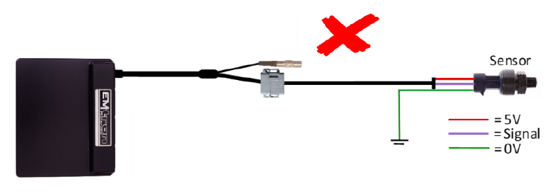
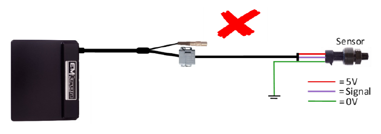
Sensor 0V Reference (Pin 1 of Expansion port) — This pin should be connected directly to the 0V (Ground) pin on any low current analog sensor, for example Pressure or Temperature.
- DO NOT connect the 0V Reference pin directly to the Engine Block or ECU Ground. This is a dedicated and specialised 0V/ground output for analog sensors.
- DO NOT connect frequency-based sensor grounds to the 0V Reference pin; for example, an Ethanol content sensor. Use Pin 8 (Ground) in the Expansion port.
Figure 3.3 — Correct Pressure Sensor 0V wiring (direct to the Sensor 0V Reference). Figure 3.4 — Incorrect Pressure Sensor 0V wiring.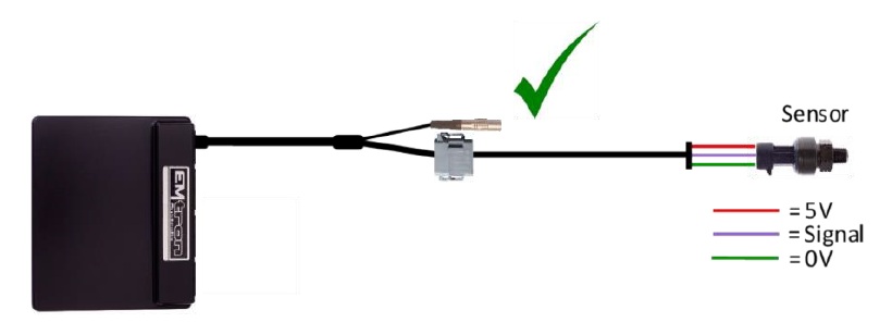
3.4 Ethanol Content Sensor Wiring
An Ethanol Content sensor can be wired into the ECU using the Expansion port. The following channel assignment is recommended for the GM sensor:
| GM Sensor Pinout | Expansion Port | Description |
|---|---|---|
| Pin 1 | Pin 9 — 14V Protected | Supply, 8V or 14V |
| Pin 2 | Pin 10 — ECU Ground | Ground |
| Pin 3 | Pin 6 — DI 6 | Output. Temperature and Ethanol Content |
NoteNOTE DO NOT connect the Ethanol Content sensor ground to the “Analog Sensor 0V Reference” — use the ECU Ground from Pin 10. The Ethanol sensor produces a frequency-based output; suitable ECU channels are DI 1-8.
| Description | Calibration |
|---|---|
| Ethanol Content (%) | 50Hz = 0% Ethanol, 150Hz = 100% Ethanol |
| Fuel Temperature | 1ms = -40°C, 5ms = 125°C |
To configure the ECU for this sensor, select the Ethanol Sensor Input Source to DI6. The ECU will automatically decode the Ethanol Content and Fuel Temperature. Once assigned, more settings become available in the Tuning View → Engine Functions menu.
4.0 ECU Channel Assignment
Injection
| ECU Channel | Function |
|---|---|
| Injection 1-4 | Fuel Injector Cyl 1-4 |
| Injection 5 | Rear Lambda Heater |
| Injection 6 | Front Lambda Heater |
| Injection 7 | A/C Fan Relay (High) |
| Injection 8 | CE Light |
| Injection 9-12 | Not Used |
Ignition
| ECU Channel | Function |
|---|---|
| Ignition 1 | Ignition Cylinder 1/4 |
| Ignition 2 | Ignition Cylinder 2/3 |
| Ignition 3 | A/C Fan Relay (Low) |
| Ignition 4 | IC Spray Lamp |
| Ignition 5 | Alternator Load Control |
| Ignition 6 | Fuel Pump Relay |
| Ignition 7 | Fuel Pump Speed Relay |
| Ignition 8 | A/C Clutch Relay |
| Ignition 9-12 | Not Used |
Analog Inputs
| ECU Channel | Function |
|---|---|
| Analog Voltage 1 | MAP |
| Analog Voltage 2 | TPS |
| Analog Voltage 3 | O2 Front |
| Analog Voltage 4 | O2 Rear |
| Analog Voltage 5-6 | Not Used |
| Analog Voltage 7 (Pull-up) | Engine Temperature |
| Analog Voltage 8 (Pull-up) | (IO Expansion port) |
| Analog Voltage 9 (Pull-up) | Intake Temperature (IAT MAF) |
| Analog Voltage 10 (Pull-up) | Fuel Tank Temp (USDM) |
| Analog Voltage 11-12 (Pull-up) | (IO Expansion port) |
| Analog Voltage 13-14 | Not Used |
Analog Voltage Channels 7-12 have switchable pull-ups suitable for temperature measurement.
Digital Inputs
| ECU Channel | Function |
|---|---|
| Digital Input 1 | MAF Reset |
| Digital Input 2 | Vehicle Speed |
| Digital Input 3 | Clutch Switch |
| Digital Input 4 | Power Steer Pressure Switch |
| Digital Input 5 | Alternator FR Signal |
| Digital Input 6 | IO Expansion port (Ethanol Sensor) |
| Digital Input 7 | MAF |
| Digital Input 8 | I/C Spray Switch - Auto |
| Digital Input 9 | I/C Spray Switch - Manual |
| Digital Input 10 | ACD Input |
| Digital Input 11 | Ignition Start |
| Digital Input 12 | A/C Pressure Switch |
| Digital Input 13-14 | IO Expansion port |
Auxiliary Outputs
| ECU Channel | Function |
|---|---|
| Auxiliary 1 | Purge Solenoid |
| Auxiliary 2 | Wastegate Solenoid |
| Auxiliary 3 | Tacho |
| Auxiliary 4 | Engine Fan Relay (EVO 7-8) - PWM |
| Auxiliary 5 | Stepper Motor A1 |
| Auxiliary 6 | Stepper Motor A2 |
| Auxiliary 7 | Stepper Motor B1 |
| Auxiliary 8 | Stepper Motor B2 |
| Auxiliary 9 | Fuel Pressure Solenoid |
| Auxiliary 10 | I/C Spray Relay |
| Auxiliary 11 | Engine Fan Relay |
| Auxiliary 12 | Sec Air/EGR Solenoid |
| Auxiliary 13 | EVO8 Crank ground / EVO7 Cat Light |
| Auxiliary 14-16 | Not Used |
Crank / Cam
| ECU Channel | Function |
|---|---|
| Crank Index | Crank Sensor |
| Sync Sensor | Cam Position - Inlet LH |
5.0 Plug-in Specific Information
5.1 Fuel Model
The base ECU calibration is supplied in Speed Density mode. It is recommended to install an Emtron 4Bar MAP sensor and wire it to a spare ANV Input in the Emtron expansion port. The ECU may also be configured to run on MAF only, or using a combination of MAF and Speed Density (MAP).
5.2 Inlet Air Temperature
ANV9 (ECU Pin 72) is assigned to the Inlet Air Temperature Sensor, which is physically located in the Mass Air Flow Meter. This is not ideal for the fuel model — it is recommended to install an inlet air temperature sensor in the inlet manifold. The Mass Air Flow Meter wiring can be reassigned, or the Air Temp sensor can be wired directly to pin 3 or 4 in the Emtron expansion port connector. ANV8, 11 or 12 may then be assigned in the inputs setup page in Emtune. Some EVO models have an inlet air temperature sensor fitted; however, this is not accounted for in the Emtron Plugin ECU — it is recommended to wire to the expansion port connector.
5.3 ECU Pin 40 Configuration
ECU Pin 40 configuration depends on the model. A low current, low side driver is connected to this pin, controlled by Auxiliary Output 13.
- EVO 8 — Crank/Cam Sensor Ground: A ground pin for the Crank and Cam sensors that acts as an immobiliser function. Aux 13 needs to be switched ON to provide a ground and allow the engine to start.
- EVO 4-7 — CAT Light: The CAT light requires a ground to switch the light on. Aux 13 can be used to control this light.
6.0 Diagnostic Trouble Codes (DTCs)
On initial installation it is advised to clear all the DTCs if errors are reported. Connect to Emtune and look at the DTC status in the bottom toolbar. If there are errors the status box will be red. To open the DTC window, click on the DTC Status box in the bottom toolbar OR use File → Open DTC. Select “Clear ALL DTCs” and confirm all the Error Codes have been removed — the DTC Status box should go green. If the error codes have not all been removed, select “Update DTC” then use the DTC window to locate the sensor that is on fault.
7.0 Ordering Information
| Product | Part Number |
|---|---|
| Emtron Mitsubishi EVO 4-8 Plugin | 1609-52248 |
| Emtron Ethernet Tuning Cable (1.5m) | 553-15 |
Appendix A – EVO 4-8 ECU Pinout
| Pin | Function | Channel Assignment |
|---|---|---|
| 1 | Injector 1 | INJ 1 |
| 2 | Injector 3 | INJ 3 |
| 3 | Fuel Pressure Solenoid | AUX 9 |
| 4 | Stepper Motor Coil A1 | AUX 5 |
| 5 | Stepper Motor Coil B1 | AUX 6 |
| 6 | EGR Solenoid Relay | AUX 12 |
| 8 | Fuel Pump Relay | IGN 6 |
| 9 | Purge Solenoid | AUX 1 |
| 10 | Ignition Coil 1 & 4 | IGN 1 |
| 11 | Wastegate Solenoid | AUX 2 |
| 12 | ECU 14V from Main Relay | ECU SUPPLY |
| 13 | Engine Block/Power Ground | ECU GROUND |
| 14 | Injector 2 | INJ 2 |
| 15 | Injector 4 | INJ 4 |
| 16 | Evaporative Purge Solenoid | AUX 1 |
| 17 | Stepper Motor Coil A2 | AUX 6 |
| 18 | Stepper Motor Coil B3 | AUX 8 |
| 19 | Volume Airflow Sensor Reset Signal | DI 1 |
| 20 | Engine Fan Speed low (EVO 4-6) | AUX 11 |
| 21 | Engine Fan PWM Control (EVO 7-8) | AUX 4 |
| 22 | A/C Clutch Relay | IGN 8 |
| 23 | Ignition Coil 2 & 3 | IGN 2 |
| 25 | ECU 14V from Main Relay | ECU SUPPLY |
| 26 | Engine Block/Power Ground | ECU GROUND |
| 32 | A/C Fan Relay High | INJ 7 |
| 33 | Alternator G Terminal | IGN 5 |
| 34 | A/C Fan Relay Low | IGN 3 |
| 35 | I/C Spray Lamp | IGN 4 |
| 36 | CE Light | INJ 8 |
| 37 | Power Steer Pressure Switch | DI 4 |
| 38 | ECU Main Relay Control | MAIN EFI RELAY |
| 39 | Fuel Pump Speed | IGN 7 |
| 40 | Crank/Cam sensor ground (EVO8) / CAT (EVO 4-7) | AUX 13 |
| 41 | Alt FR terminal (Field response) - Freq Based | DI 5 |
| 43 | Clutch Switch | DI 3 |
| 44 | I/C Spray Switch - Auto | DI 8 |
| 45 | AC Pressure Switch | DI 12 |
| 51 | Immobiliser | |
| 53 | Sec Air Solenoid (EVO7) | AUX 12 |
| 54 | O2 Heater Rear | INJ 5 |
| 55 | I/C Spray Relay (EVO7) | AUX 10 |
| 56 | Diagnostics – OBD II Pin 1 | |
| 57 | I/C Spray Relay (EVO8) | AUX 10 |
| 58 | Tacho | AUX 3 |
| 60 | O2 Heater Front | INJ 6 |
| 62 | Diagnostics – OBD II Pin 7 | |
| 71 | Start Switch | DI 11 |
| 72 | Intake Air Temperature | ANV 8 |
| 73 | Manifold Absolute Pressure Sensor | ANV 1 |
| 75 | O2 Sensor Signal Rear | ANV 4 |
| 76 | O2 Sensor Signal Front | ANV 3 |
| 77 | Fuel Tank Temperature (USDM) | ANV 10 |
| 78 | Knock Sensor | KNOCK 1+ |
| 80 | Battery Backup (+12 Constant) | Internal Flywheel Supply |
| 81 | + 5V Supply | +5V Vref1 |
| 82 | Ignition Switch | Ignition Switch |
| 83 | Engine Coolant Temperature | ANV 7 |
| 84 | Throttle Position Sensor | ANV 2 |
| 85 | External Barometric Pressure | |
| 86 | Vehicle Speed | DI 2 |
| 87 | ACD Signal/Idle Switch | DI 10 |
| 88 | Cam Signal | Sync Sensor |
| 89 | Crank Signal | Crank Index |
| 90 | Volume Air Flow Sensor | DI 7 |
| 91 | I/C Spray Switch – Manual (EVO 7-8) | DI 9 |
| 92 | Sensor Ground (MAP, TPS) | Sensor 0V Reference |
Mitsubishi EVO 9
Mitsubishi EVO 9 Plug-in ECU User Manual
1.0 Introduction
The Mitsubishi EVO 9 ECU is designed to be plugged into the OEM harness to allow for a true “Plug and Play” install. The system is based on the KV Series Motorsport ECU, so all the same features are available with the limitation based around the OEM connector system. An Expansion loom is included giving access to unused Input channels. CAN Bus 2 is also available providing additional I/O expandability.
2.0 Plugin Features
General
- KV8 ECU based platform — Dual 100MHz processors, 32MB ECU logging memory, over 1000 logging channels, 1Hz to 500Hz logging rate
- Aluminium 6061 Grade CNC billet enclosure
- Compatible with all Emtron proven motorsport features (Launch Control, Rolling Launch, Anti-Lag, Traction Control)
- Upgradeable to run the Emtron fuel model through installation of a flex meter, fuel temperature and fuel pressure sensor
- Idle speed closed loop control using DBW with advanced Throttle Mass Flow (TMF) airflow calculations
- Knock control with high speed digital filtering for each cylinder using the OEM sensor with selectable centre frequency and bandwidth
- Pre-configured calibration file loaded providing a comprehensive tuning platform
- Input Expansion Capabilities through DTM connector: 3× User Analog Volt Inputs (Fuel Temperature, Fuel Pressure, Inlet Temperature), 3× User Digital Input (Flex Meter Input and switch inputs)
- Emtune software for tuning and data analysis
Communications: CAN 2.0B Bus 2 (User CAN Bus for I/O expansion — Lambda, EGT); High Speed Ethernet 100Mbps for tuning software connection.
Operating Temperature: -30 to 85°C (-22 to 185°F)
Physical: Enclosure Size 160 × 162 × 38 mm, 890g
3.0 Installation
3.1 Expansion Port
The ECU’s input capabilities can be expanded using the expansion connection, which is a male DTM 12 Way. These additional inputs can be connected to any sensor, but the recommended sensors are indicated in brackets.
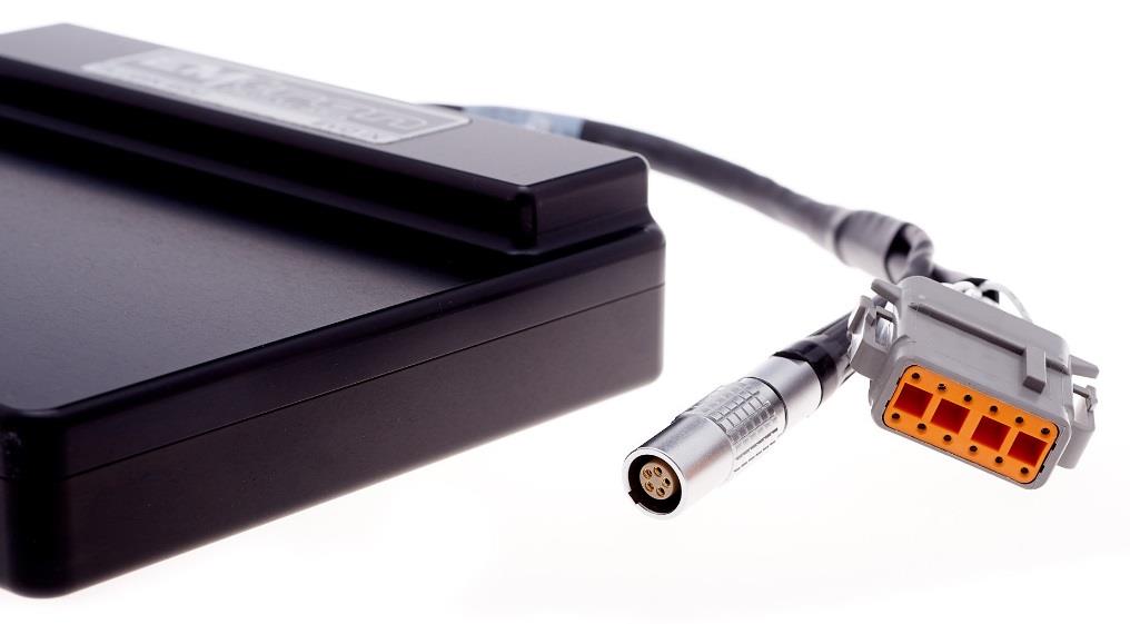
EVO 9 expansion port connector (DTM 12-way).
Table 3.0 — Expansion Port Pinout (DTM06-12SA)
| Pin | Function |
|---|---|
| 1 | Analog Sensor 0V Reference |
| 2 | 5V Vref2 Supply |
| 3 | AN 8 (e.g. Fuel Temp or Inlet Temp) |
| 4 | AN 9 (e.g. Fuel Temp or Inlet Temp) |
| 5 | AN 10 (e.g. Fuel Pressure) |
| 6 | DI 6 (e.g. Ethanol Content Sensor) |
| 7 | 14V Out Protected (e.g. ELC2 Power Supply). Post ECU SN 2700 only. |
| 8 | ECU Ground (e.g. ELC2 or E85 Sensor Ground). Post ECU SN 2700 only. |
| 9 | DI 13 |
| 10 | DI 14 |
| 11 | CAN 2 Hi |
| 12 | CAN 2 Lo |
3.2 CAN Bus 2 Wiring
The ECU CAN Bus 2 is reserved for Emtron CAN Bus devices, expanding the IO capability of the ECU. The following devices can be connected: ELC1/2 (Lambda to CAN), ETC4/ETC8M (Thermocouple to CAN), EIC10/EIC16M (Input to CAN). All these CAN devices share a common power, ground and CAN pinout using a 4-way DTM.
Table 3.1 — CAN Device Power and CAN Deutsch Connector Pinout
| Pin | Function | Wire Colour |
|---|---|---|
| 1 | Ground | BLACK |
| 2 | CAN Lo | GREEN |
| 3 | CAN Hi | YELLOW |
| 4 | 12V Supply | RED |
To help with installation time, each CAN Device pin can be directly connected into the ECU IO Expansion port:
Table 3.2 — IO Expansion to CAN Device wiring
| Name | ECU IO Expansion 12-Way DTM | CAN Device 4-Way DTM |
|---|---|---|
| Ground | Pin 8 | Pin 1 |
| CAN 2 Lo | Pin 12 | Pin 2 |
| CAN 2 Hi | Pin 11 | Pin 3 |
| Power | Pin 7 | Pin 4 |
Standard CAN bus precautions apply — twisted pair (min one twist per 40mm), minimise connectors, 120 ohm 0.25W termination at each END, stub length < 0.3m (ISO 11898). All Emtron CAN devices have no on-board terminating resistor, allowing them to be wired at any position on the Bus.
3.3 Sensor Wiring
5V VRef2 Sensor Supply (Pin 2 of Expansion port) — A 250mA 5V output designed to supply automotive sensors.
Sensor 0V Reference (Pin 1 of Expansion port) — This pin should be connected directly to the 0V (Ground) pin on any low current analog sensor, for example Pressure or Temperature.
- DO NOT connect the 0V Reference pin directly to the Engine Block or ECU Ground. This is a dedicated and specialised 0V/ground output for analog sensors.
- DO NOT connect frequency-based sensor grounds to the 0V Reference pin; for example, an Ethanol content sensor. Use Pin 8 (Ground) in the Expansion port.
Figure 3.3 — Correct Pressure Sensor 0V wiring (direct to the Sensor 0V Reference). Figure 3.4 — Incorrect Pressure Sensor 0V wiring.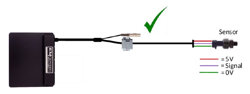
3.4 Ethanol Content Sensor Wiring
An Ethanol Content sensor can be wired into the ECU using the Expansion port. The following channel assignment is recommended for the GM sensor:
| GM Sensor Pinout | Expansion Loom | Description |
|---|---|---|
| Pin 1 | Pin 9 — 14V Protected | Supply, 8V or 14V |
| Pin 2 | Pin 10 — ECU Ground | Ground |
| Pin 3 | Pin 6 — DI 6 | Output. Temperature and Ethanol Content |
NoteNOTE DO NOT connect the Ethanol Content sensor ground to the “Analog Sensor 0V Reference” — use the ECU Ground from Pin 10. The Ethanol sensor produces a frequency-based output; suitable ECU channels are DI 1-8.
| Description | Calibration |
|---|---|
| Ethanol Content (%) | 50Hz = 0% Ethanol, 150Hz = 100% Ethanol |
| Fuel Temperature | 1ms = -40°C, 5ms = 125°C |
To configure the ECU for this sensor, select the Ethanol Sensor Input Source to DI6. The ECU will automatically decode the Ethanol Content and Fuel Temperature. Once assigned, more settings become available in the Tuning View → Engine Functions menu.
4.0 ECU Channel Assignment
Injection
| ECU Channel | Function |
|---|---|
| Injection 1-4 | Fuel Injector Cyl 1-4 |
| Injection 5 | Rear Lambda Heater |
| Injection 6 | Front Lambda Heater |
| Injection 7 | Purge Solenoid 1 |
| Injection 8 | Secondary Air Solenoid |
| Injection 9-12 | Not Used |
Ignition
| ECU Channel | Function |
|---|---|
| Ignition 1 | Ignition Cylinder 1/4 |
| Ignition 2 | Ignition Cylinder 2/3 |
| Ignition 3 | I/C Spray Lamp |
| Ignition 4 | Alternator Load Control |
| Ignition 5 | Fuel Pump Relay |
| Ignition 6 | Fuel Pump Speed Relay |
| Ignition 7 | A/C Clutch Relay |
| Ignition 8 | CE Light |
| Ignition 9 | A/C Fan High |
| Ignition 10 | A/C Fan Low |
| Ignition 11-12 | Not Used |
Analog Inputs
| ECU Channel | Function |
|---|---|
| Analog Voltage 1 | MAP |
| Analog Voltage 2 | TPS |
| Analog Voltage 3 | O2 Front |
| Analog Voltage 4 | O2 Rear |
| Analog Voltage 5 | MAF Baro |
| Analog Voltage 6 | Fuel Level |
| Analog Voltage 7 (Pull-up) | Engine Temperature |
| Analog Voltage 8-10 (Pull-up) | IO Expansion port |
| Analog Voltage 11 (Pull-up) | Intake Temperature in MAF |
| Analog Voltage 12 (Pull-up) | Fuel Tank Pressure (US Models) |
| Analog Voltage 13-14 | Not Used |
Analog Voltage Channels 7-12 have switchable pull-ups suitable for temperature measurement.
Digital Inputs
| ECU Channel | Function |
|---|---|
| Digital Input 1 | Cam Position - Inlet |
| Digital Input 2 | Vehicle Speed |
| Digital Input 3 | Clutch Switch |
| Digital Input 4 | Power Steer Pressure Switch |
| Digital Input 5 | A/C Switch 2 |
| Digital Input 6 | IO Expansion Loom (Ethanol Sensor) |
| Digital Input 7 | MAF |
| Digital Input 8 | I/C Spray Switch - Auto |
| Digital Input 9 | I/C Spray Switch - Manual |
| Digital Input 10 | Fuel Level Low Light |
| Digital Input 11 | Ignition Start |
| Digital Input 12 | A/C Pressure Switch |
| Digital Input 13-14 | IO Expansion port |
Auxiliary Outputs
| ECU Channel | Function |
|---|---|
| Auxiliary 1 | VVT Inlet Solenoid |
| Auxiliary 2 | Wastegate Solenoid |
| Auxiliary 3 | Tacho |
| Auxiliary 4 | Engine Fan Relay |
| Auxiliary 5 | Stepper Motor B1 |
| Auxiliary 6 | Stepper Motor A1 |
| Auxiliary 7 | Stepper Motor A2 |
| Auxiliary 8 | Stepper Motor B1 |
| Auxiliary 9 | Fuel Pressure Solenoid |
| Auxiliary 10 | I/C Spray Relay |
| Auxiliary 11 | EGR Solenoid |
| Auxiliary 12 | Evap Ventilation Solenoid |
| Auxiliary 13-16 | Not Used |
Auxiliary Channel 9/10 can be reconfigured to run DBW.
Crank / Cam
| ECU Channel | Function |
|---|---|
| Crank Index | Crank Sensor |
| Sync Sensor | Cam Position - Inlet LH |
5.0 Plug-in Specific Information
5.1 Fuel Model
The base ECU calibration is supplied in Speed Density mode. It is recommended to install an Emtron 4Bar MAP sensor and wire it to an unused ANV Input in the Emtron expansion port. The ECU may also be configured to run on MAF only, or using a combination of MAF and Speed Density (MAP).
5.2 Inlet Air Temperature
ECU Pin 62 is assigned to the Intake Air Temperature (MAF), which is physically located in the Mass Air Flow Meter. This is not ideal for the fuel model — it is recommended to install an inlet air temperature sensor in the inlet manifold, wired directly to pin 3 in the Emtron expansion port connector. ANV8 may then be assigned in the inputs setup page in Emtune. Some models have an inlet air temperature sensor fitted in the plenum, connected to Pin 94 in the ECU and also assigned to ANV8 — if the vehicle is already fitted with a plenum-mounted sensor the input channel simply needs to be assigned.
NoteNOTE If the OEM sensor is fitted, pin 3 on the Emtron expansion port will no longer be available (unless that sensor is disconnected) as the pin is shared.
5.3 Drive by Wire (DBW)
Auxiliary Channels 9 and 10 can be reconfigured to run DBW.
| Channel | OEM Configuration | Reconfigured |
|---|---|---|
| Auxiliary Output 9 | Fuel Pressure Solenoid | DBW Motor + |
| Auxiliary Output 10 | I/C Spray Relay | DBW Motor - |
6.0 Diagnostic Trouble Codes (DTCs)
On initial installation it is advised to clear all the DTCs if errors are reported. Connect to Emtune and look at the DTC status in the bottom toolbar (red if errors are present). Open the DTC window via the DTC Status box or File → Open DTC, select “Clear ALL DTCs”, and confirm all the Error Codes have been removed (status box goes green). If the error codes have not all been removed, select “Update DTC” then use the DTC window to locate the sensor that is on fault.
7.0 Ordering Information
| Product | Part Number |
|---|---|
| Emtron Mitsubishi EVO 9 Plugin | 1609-5229 |
| Emtron Ethernet Tuning Cable (1.5m) | 553-15 |
Appendix A – EVO 9 ECU Pinout
| Pin | Function | Channel Assignment |
|---|---|---|
| 1 | Injector 1 | INJ 1 |
| 2 | Injector 4 | INJ 2 |
| 3 | Front O2 Heater | INJ 6 |
| 4 | Secondary Air Solenoid | INJ 8 |
| 6 | EGR Solenoid Relay | AUX 11 |
| 8 | Alternator G Terminal | IGN 4 |
| 9 | Injector 2 | INJ 2 |
| 11 | Ignition Coil 1 & 4 | IGN 1 |
| 12 | Ignition Coil 2 & 3 | IGN 2 |
| 14 | Stepper Motor Coil A1 | AUX 6 |
| 15 | Stepper Motor Coil B1 | AUX 5 |
| 16 | Evaporative Purge Solenoid | INJ 7 |
| 18 | Engine Fan (4kHz) | AUX 4 |
| 19 | Volume Airflow Sensor Reset Signal | |
| 20 | A/C Compressor Clutch Relay | IGN 7 |
| 21 | Fuel Pump Relay | IGN 5 |
| 22 | Check Engine Indicator Lamp | IGN 8 |
| 24 | Injector 3 | INJ 3 |
| 26 | Rear O2 Sensor Heater (USDM) | INJ 5 |
| 28 | Stepper Motor Coil A2 | AUX 7 |
| 29 | Stepper Motor Coil B2 | AUX 8 |
| 30 | A/C Condenser Fan Relay (Low) | IGN 9 |
| 31 | A/C Condenser Fan Relay (High) | IGN 10 |
| 32 | MIVEC Oil Control Solenoid | AUX 1 |
| 34 | Sensor Ground (CAS, AFM) | ECU GROUND |
| 35 | Evaporative Ventilation Solenoid (USDM) | AUX 12 |
| 41 | Wastegate Solenoid #1 | AUX 2 |
| 42 | + 5V Supply | +5V Vref1 |
| 43 | Crank Signal | Crank Index + |
| 44 | Engine Coolant Temperature | ANV 7 |
| 45 | Tacho | AUX 3 |
| 46 | Engine Block/Power Ground | ECU Ground |
| 47 | ECU 14V from Main Relay | ECU Supply |
| 48 | Fuel Pressure Solenoid | AUX 9 |
| 49 | Sensor Ground (MAP, TPS) | Sensor 0V Reference |
| 50 | CAM Angle Sensor (Exhaust Cam) | Sync Sensor |
| 51 | Barometric Pressure Sensor (MAF) | ANV 5 |
| 52 | Alt FR terminal (Field response) - Freq Based | |
| 53 | Inlet Cam Position Sensor | DI 1 |
| 54 | Power Steer Pressure Switch | DI 4 |
| 55 | Fuel Pump Speed Relay | IGN 6 |
| 56 | I/C Spray Relay | AUX 10 |
| 57 | Main Relay (Gnd to operate) | EFI RELAY |
| 58 | Engine Block/Power Ground | ECU Ground |
| 59 | ECU 14V from Main Relay | ECU Supply |
| 60 | Battery Backup (+12 Constant) | Internal Flywheel Supply |
| 61 | Volume Air Flow Sensor | DI 7 |
| 62 | Intake Air Temp Sensor (MAF) | ANV 11 |
| 63 | Wastegate Solenoid #2 | AUX 2 |
| 65 | A/C Switch | DI 5 |
| 66 | I/C Auto Switch | DI 8 |
| 67 | I/C Manual Switch | DI 9 |
| 68 | Ignition Start Signal | DI 11 |
| 71 | O2 Sensor Signal Front | ANV 3 |
| 73 | O2 Sensor Signal Rear | ANV 4 |
| 75 | (N/C) | ECU Ground |
| 78 | Throttle Position Sensor | ANV 2 |
| 80 | Vehicle Speed | DI 2 |
| 83 | A/C Request (Pressure Switch) | DI 12 |
| 85 | Diagnostics K-line (OBD Pin 7) | |
| 88 | Clutch Switch | DI 3 |
| 90 | I/C Spray Lamp | IGN 3 |
| 91 | Knock Sensor | Knock 1 + |
| 92 | Manifold Absolute Pressure Sensor | ANV 1 |
| 93 | Fuel Tank Differential Pressure Sensor | ANV 12 |
| 95 | Fuel Level | ANV 6 |
| 96 | Inlet Plenum Temperature | ANV 8 |
| 97 | Fuel Level Low (USDM) | DI 10 |
| 98 | Immobiliser | |
| 99 | Ignition Switch | Ignition Switch |
| 100 | Diagnostics |
Nissan GTR R35
Documentation for the Emtron R35 GT-R Plug-in ECU — installation, VDC integration, TCM setup, and tuning.
Start with Nissan GTR R35 Build for the plug-in installation reference.
Subsections of Nissan GTR R35
Nissan GTR R35 Build
Nissan GT-R R35
Nissan GTR R35 dedicated menu shown with GTR R35 build enabled
The Nissan R35 GT-R’s turbo control system and monitoring is different than many turbocharged cars.
Commonly turbocharged engines have a common plenum that feeds all the engines cylinders.
Each cylinder draws air from a common plenum.
On the Nissan R35 GT-R one bank feeds one set of three cylinders(1-3) and the other turbo feeds the other three cylinders (4-6) via separated plenum’s. There is also a cross over balance pipe between the plenum’s.
To correctly calculate the fueling requirements for each bank the ECU uses MAF Meter 1 (Bank 1) to control the fueling on Cylinders 1-3 and MAF Meter 2 (Bank 2) to control the fueling on Cylinders 4-6. There are also boost pressure sensors on each bank along with a single manifold pressure sensor on one bank. These pressure sensors allow for various calculations to be made by the ECU, offering a number methods to use for fuel calculations.
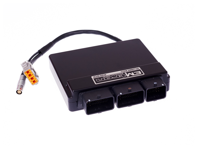
The Emtron R35 GT-R Plug-in ECU is a replacement engine management system designed to be installed and integrate seamlessly with the vehicle, whilst also allowing extreme flexibility and control from the KV12 based ECU platform.
The Nissan GTR R35 tab allows access to dedicated R35 features:
▪ Nissan Vehicle Dynamic Control (VDC) – This system employs an extremely complex system of vehicle sensors including wheel speed, steering angle, g-force and yaw which are used to generate various torque requests which the ECU must abide by accurately. This will not only achieve maximum vehicle performance, it is also a safety feature.
▪ Nissan Transmission Control Module Integration (TCM) - The ECU must accurately calculate and perform torque requests assigned by the TCM for the drive-train to function correctly and smoothly for all driving conditions. Limitations on the transmission torque capacity must also be considered and hence another reason why the torque supplied by the engine must be accurately metered.
▪ Launch Control – The TCM provides the ECU torque requests during a launch OFF mode and is able to place the ECU into launch mode where the Torque Limit is not requested, allowing the ECU to increase the launch limit through a raised engine speed limit and an ECU determined torque limit.
▪ Downshift Rev Matching – The ECU must accurately calculate and increase torque to smoothly match the engine RPM in the next gear on downshift, by increasing the throttle mass flow (TMF) during the downshift event until the TCM is satisfied with the engine speed and torque levels.
NoteNOTE This page covers the plug-in install reference. For the detailed dedicated R35 tuning menus see Nissan GTR R35 VDC, Nissan GTR R35 TCM and TCM Torque Limit Engine Cut Setup.
Plugin Features
- KV12 ECU based platform — Dual 100MHz processors, 32MB ECU logging memory, over 1000 channels, 1Hz to 500Hz logging rate, Emtune software, Dual Knock Control using Bosch digital filtering
- 6061 Grade Aluminium CNC Billet Enclosure
- Fully compatible with all OEM systems and user programmable, including Vehicle Dynamic Control (VDC) via throttle torque reduction, Transmission (TCM) Torque and Shift Management, and Torque Management Launch Control
- Compatible with all Emtron proven motorsport features
- Sequential Staged injection option available through the OEM header
- Upgradeable to run the Emtron Fuel model through installation of a Flex Meter, Fuel Temperature and Fuel Pressure Sensor
- Input Expansion through DTM connector: 2× User Analog Volt Inputs (Fuel Temperature and Pressure), 1× User Digital Input (Flex Meter Input)
Communications: CAN 2.0B Node 1 — User CAN Bus for I/O expansion (Lambda, EGT); CAN 2.0B Node 2 — 500k Baud Full CAN Bus OEM Integration; High Speed Ethernet 100Mbps.
Operating Temperature: -30 to 125°C (-22 to 257°F). Physical: 160 × 162 × 38 mm, 890g.
Kit Contents
When purchasing a Nissan R35 plug-in the following items are included:
- GTR R35 Plug-in ECU
- Ethernet Communications Cable
- 12 way DTM to ELC Adapter Loom (120 Ohm CAN Termination resistors preinstalled)
- ELC2 Dual Channel Lambda to CAN controller – LSU4.9 version
- 2 × LSU4.9 Lambda Sensors + 2 × LSU4.9 Sensor Extension Looms
- ECU Mounting Kit
Expansion Loom
The ECU’s Input capabilities can be expanded using the expansion connection, which is a male DTM 12 Way. These additional inputs can be connected to any sensor, but the recommended sensors are indicated in brackets.
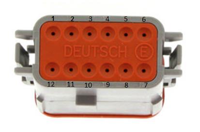
DTM 12 Way expansion loom connector (ECU side).
| Pin | Function |
|---|---|
| 1 | Analog Sensor 0V Reference |
| 2 | 5V Aux Supply |
| 3 | AN 10 (e.g. Fuel Temp or Inlet Temp) |
| 4 | Not Used |
| 5 | AN 6 (e.g. Fuel Pressure) |
| 6 | DI 6 (e.g. Ethanol Content Sensor) |
| 7 | 14V Out Protected (ELC2 Power Supply) |
| 8 | Ground (ELC2 Ground) |
| 9 | 14V Out Protected (ELC2 Power Supply) |
| 10 | Ground (ELC2 Ground) |
| 11 | CAN 1 Hi |
| 12 | CAN 1 Lo |
ECU Channel Assignment
Injection
| ECU Channel | Function |
|---|---|
| Injection 1-12 | Fuel Injector Cylinder 1-12 |
Ignition
| ECU Channel | Function |
|---|---|
| Ignition 1-6 | Ignition Cylinder 1-6 |
| Ignition 7 | DBW Relay |
| Ignition 8 | Spare |
| Ignition 9-12 | Not Used |
Analog Inputs
| ECU Channel | Function |
|---|---|
| Analog Voltage 1 | MAP |
| Analog Voltage 2 | DBW Servo Position Main Bank 1 |
| Analog Voltage 3 | DBW Servo Position Sub Bank 1 |
| Analog Voltage 4 | DBW Servo Position Main Bank 2 |
| Analog Voltage 5 | DBW Servo Position Sub Bank 2 |
| Analog Voltage 6 | Fuel Pressure |
| Analog Voltage 7 (Pull-up) | Engine Temperature |
| Analog Voltage 8 (Pull-up) | Airbox Temperature |
| Analog Voltage 9 (Pull-up) | Engine Oil Temperature |
| Analog Voltage 10 (Pull-up) | IO Expansion loom (Emtron Fuel Temp/IAT) |
| Analog Voltage 11 (Pull-up) | Pedal Position Sensor (PPS) Main |
| Analog Voltage 12 (Pull-up) | Pedal Position Sensor (PPS) Sub |
| Analog Voltage 13 | MAF Bank 1 |
| Analog Voltage 14 | MAF Bank 2 |
Digital Inputs
| ECU Channel | Function |
|---|---|
| Digital Input 1 | Cam Position - Inlet RH |
| Digital Input 2 | Brake Switch |
| Digital Input 3 | Neutral Switch |
| Digital Input 4 | Fuel Level |
| Digital Input 5 | Steering Wheel Button |
| Digital Input 6 | IO Expansion Loom (Ethanol Sensor) |
| Digital Input 7 | FP Feedback Sec Pump |
| Digital Input 8 | FP Feedback Prim Pump |
| Digital Input 9 | Power Steering Pressure |
| Digital Input 10 | Evap System Pressure |
| Digital Input 11 | Secondary Air MAF Sensor |
| Digital Input 12 | Boost Pressure Bank 1 |
| Digital Input 13 | Boost Pressure Bank 2 |
| Digital Input 14 | AC System Pressure |
Auxiliary Outputs
| ECU Channel | Function |
|---|---|
| Auxiliary 1 | VVT Solenoid Bank 1 |
| Auxiliary 2 | VVT Solenoid Bank 2 |
| Auxiliary 3 | Purge |
| Auxiliary 4 | Wastegate Solenoid |
| Auxiliary 5 | Sub Fuel Pump |
| Auxiliary 6 | Purge Vent |
| Auxiliary 7 | Fuel Pump Speed Control |
| Auxiliary 8 | Tacho |
| Auxiliary 9 | DBW + Bank 1 |
| Auxiliary 10 | DBW – Bank 1 |
| Auxiliary 11 | DBW + Bank 2 |
| Auxiliary 12 | DBW – Bank 2 |
| Auxiliary 13 | Air Pump Relay |
| Auxiliary 14 | Air Cut Solenoid Relay Control (Bank 1 & 2) |
| Auxiliary 15 | Narrow Band Sensor Heater |
| Auxiliary 16 | Not Used |
Crank / Cam
| ECU Channel | Function |
|---|---|
| Crank Index | Crank Sensor |
| Sync Sensor | Cam Position - Inlet Bank 1 (LH) |
Plug-in Specific Information
Staged Injection
Injector channels 7-12 are available in the OEM header and can be used for additional outputs or for Sequential Staged Injection: Injector Ch 7 = A11, Ch 8 = A12, Ch 9 = A16, Ch 10 = A35, Ch 11 = A39, Ch 12 = A43.
Fuel Model
The base calibration is supplied with a Blend method of MAP Modelled (MAP Sensor and MAP Estimate) and Mass Air Flow (MAF Sensor). A fully adjustable combination of Throttle Pressure Ratio and Air Mass balances the priority of the two inputs. Many other fuel modelling methods are possible, including removing the MAF Sensors completely — a common implementation when the OEM sensors don’t allow enough flow, or when engine modifications (cams, air bypass valves, larger turbos, modified intake piping) generate unstable Mass Flow readings. When MAF is selected, the Secondary Load table can be used to scale the MAF (switch ON via Fuel Menu → Fuel Table Control → Secondary Load Table, set to 12).
Inlet Air Temperature
A factory-fitted Inlet Temperature Sensor is available on Analog Input 8 and should already be configured in the base calibration.
Check Engine Light / Air-Con Switch
Both are handled through the CAN bus; the base calibration has the CE Light output and Air-Con Switch input source already configured and selected to “CAN Bus OEM”.
User CAN Bus 1
The ECU CAN Bus 1 is available for I/O expansion (ELC1/2, ETC4/ETC8M, EIC10/EIC16M). The ELC Power, Ground and CAN wires connect directly into the ECU IO Expansion Loom using the supplied 12 way DTM to ELC Adapter Loom (120 Ohm termination resistors pre-installed — completely plug and play). If other devices are added to the CAN bus, ensure no additional resistors are introduced.
| Name | ELC 4-Way DTM | ECU IO Expansion 12-Way DTM |
|---|---|---|
| Ground | Pin 1 | Pin 8 |
| CAN Lo | Pin 2 | Pin 12 |
| CAN Hi | Pin 3 | Pin 11 |
| Power | Pin 4 | Pin 7 |
OEM CAN Bus 2
The ECU communicates on CAN Bus 2, reserved for the R35 GT-R, maintaining full compatibility with all other CAN devices in the vehicle. Emtune has a dedicated R35 GT-R runtime tab; these runtimes are available throughout the ECU’s functions and viewable in the Emtune logger.
Emtron Torque Management
The ECU performs accurate torque calculations provided the engine model configuration is accurate. The Torque Management section allows the user to calibrate errors in the torque model whilst influencing torque delivery: Torque Reduction Ign Retard Clamp, Torque Nitrous Gain, BSFC, Engine Torque Correction Table, Torque Demand Correction Table, Frictional Loss Table (+ Offset 1 Table, commonly spanned against Engine Oil Temperature), Torque Reduction Ignition Retard Gain Table (% per degree) and Torque Reduction Gain Table (% per %cut).
Launch Control
Launch Control is enabled in the base calibration. The TCM controls how it is armed — the ECU arms based on enabling R Mode of the transmission. The feature allows the user to target a torque level; the base calibration leverages Engine Speed Limit 2 (RPM Limit 2 Table) to control engine speed during launch. The correct torque target achieves good acceleration and traction without requiring engine speed limiting once the vehicle is moving.
Communications Torque
Torque information over the CAN bus can be modified (a ±500Nm offset table), changing gearshift behaviour and in-gear clutch pressure. If there is excessive slip, increase the reported Torque; if the gearshift feel is too sharp/aggressive, reduce it. This affects Engine Torque Demand and Engine Torque. Note: directly programming the TCM through a third-party flashing tool is advised over using the ECU to offset the torque reported.
Ordering Information
| Product | Part Number |
|---|---|
| Emtron R35 Plugin | 1609-1835 |
Appendix A – ECU Pinout
Connector A
| OEM Pin | Function | Channel Assignment |
|---|---|---|
| A1 | Throttle Control Motor Supply (paired with pin 49) | AUX 9-12 Supply (option 2) |
| A2 | Throttle Servo Bank 2 Motor + | AUX11 |
| A3 | AF Sensor 2 Heater (denso narrowband) | AUX15 |
| A4 | AF Sensor 1 Heater (denso narrowband) | AUX15 |
| A5 | Throttle Servo Bank 2 Motor - | AUX12 |
| A6 | Power Ground | GROUND |
| A7 | Evaporative Purge Canister Vent Control Valve | AUX6 |
| A8 | Evaporative Purge Canister Volume Control Solenoid | AUX3 |
| A9 | Ignition Cylinder 2 | Ignition Channel 2 |
| A10 | Ignition Cylinder 1 | Ignition Channel 1 |
| A11 | Secondary Injector 1 | Injector Channel 7 |
| A12 | Secondary Injector 2 | Injector Channel 8 |
| A13 | Ignition Cylinder 3 | Ignition Channel 3 |
| A15 | TPS Bank 2 Ground | Sensor Ground 1 |
| A16 | Secondary Injector 3 | Injector Channel 9 |
| A17 | Fuel Injector Cylinder 3 | INJ 3 |
| A19 | MAF Sensor Bank 2 Ground | Sensor Ground 1 |
| A20 | TPS Bank 1 Ground | Sensor Ground 1 |
| A21 | Fuel Injector Cylinder 2 | INJ 2 |
| A22 | MAF Sensor Bank 1 Ground | Sensor Ground 1 |
| A23 | SAMAF and TAM Ground | Sensor Ground 1 |
| A24 | Secondary Air Injection MAF Sensor (SAMAF) | DI 11 |
| A25 | Fuel Injector Cylinder 1 | INJ 1 |
| A26 | Engine Oil Temp / Engine Temp Ground | Sensor Ground 1 |
| A27 | Engine Oil Temperature | ANV9 |
| A28 | Throttle Servo Bank 2 Position Main | ANV4 |
| A29 | Fuel Pump Control Signal | AUX7 |
| A30 | Fuel Pump Control Diag Input | DI 8 |
| A31 | Mass Flow Sensor Bank 1 | ANV13 |
| A32 | Throttle Servo Bank 2 Position Tracking | AV5 |
| A33 | Ignition Cylinder 4 | Ignition Channel 4 |
| A34 | Ignition Cylinder 5 | Ignition Channel 5 |
| A35 | Secondary Injector 4 | Injector Channel 10 |
| A36 | Throttle Servo Bank 1 Position Tracking | ANV3 |
| A37 | Fuel Injector Cylinder 4 | INJ 4 |
| A38 | Ignition Cylinder 6 | Ignition Channel 6 |
| A39 | Secondary Injector 5 | Injector Channel 11 |
| A40 | Throttle Servo Bank 1 Position Main | ANV 1 |
| A41 | Fuel Injector Cylinder 5 | INJ 5 |
| A42 | Fuel Level Sensor | ANV 10 |
| A43 | Secondary Injector 6 | Injector Channel 12 |
| A44 | Airbox Temperature | ANV8 |
| A45 | Fuel Injector Cylinder 6 | INJ 6 |
| A46 | Coolant Temperature | ANV7 |
| A47 | Inlet Mass Flow Bank 2 | ANV14 |
| A48 | Inlet Manifold Pressure Bank 2 | ANV1 |
Connector B
| OEM Pin | Function | Channel Assignment |
|---|---|---|
| B49 | Throttle Control Motor Supply (paired with pin 1) | Aux 9-12 Supply (option 1) |
| B50 | Throttle Servo Bank 1 Motor + | AUX 9 |
| B51 | Inlet Camshaft Bank 2 Solenoid | AUX 2 |
| B52 | Inlet Camshaft Bank 1 Solenoid | AUX 1 |
| B53 | Throttle Servo Bank 1 Motor - | AUX 10 |
| B54 | Power Ground | GROUND |
| B55 | O2HR1 - Wideband bank 1 Heater | Not Connected |
| B56 | O2HR2 - Wideband bank 2 Heater | Not Connected |
| B61 | Boost Control Solenoid | AUX 4 |
| B62 | Ground - Camshaft Position Bank 1 | Sync Sensor - |
| B63 | Camshaft Bank 1 Position Sensor (inlet) | Sync Sensor + |
| B64 | Crankshaft Position Sensor | Crank Index + |
| B66 | Ground - Camshaft Position Bank 2 | Sync Sensor - |
| B67 | Camshaft Bank 2 Position Sensor (Inlet) | DI 1 |
| B68 | Ground - Crankshaft Position Sensor | Crank Index - |
| B70 | Ground - WB Sensor 1 and 2 (joined in loom) | GROUND |
| B71 | Knock Sensor Ground for Bank 1 and 2 (joined) | ECU Ground |
| B72 | Knock Sensor Bank 1 | Knock 1 + |
| B73 | O2SR1 - Wideband bank 1 sensor | Not Connected |
| B74 | Ground (Power Steer Pres, MAP, Refrigerant Pres) | Sensor Ground 1 |
| B75 | Ground (Evap sensor, Boost sensor Bank 1 and 2) | Sensor Ground 1 |
| B76 | Knock Sensor Bank 2 | Knock 2 + |
| B77 | O2SR2 - Wideband bank 2 sensor | Not Connected |
| B78 | Evap Control System Pressure Sensor | DI 10 |
| B79 | Boost Pressure Bank 2 | DI12 |
| B80 | Boost Pressure Bank 1 | DI13 |
| B81 | Denso Sensor AF+ (Bank 1 Narrowband) | Not Connected |
| B82 | Denso Sensor AF- (Bank 1 Narrowband) | Sensor Ground 1 |
| B83 | Power Steering Pressure | DI 9 |
| B84 | 5V Supply - TPS Bank 2 | 5V Engine Supply |
| B85 | Denso Sensor AF+ (Bank 2) | Not Connected |
| B86 | Denso Sensor AF- (Bank 2) | Sensor Ground 1 |
| B87 | 5V Supply - Crankshaft | 5V Trigger Supply |
| B88 | 5V Supply - Camshaft Position Bank 1 | 5V Trigger Supply |
| B89 | Air Conditioner Refrigerant Pressure | DI 14 |
| B91 | 5V Supply - Camshaft Position Bank 2 | 5V Trigger Supply |
| B92 | 5V Supply - Evap sensor, Boost sensor Bank 1/2 | 5V Aux Supply |
| B93 | Sub Fuel Pump + (feedback) | DI 7 |
| B94 | Sub Fuel Pump - (feedback) | Not Connected |
| B95 | 5V Supply - Power Steer Pres, MAP, Refrig Pres | 5V Engine Supply |
| B96 | 5V Supply - TPS Bank 1 | 5V Engine Supply |
Connector C
| OEM Pin | Function | Channel Assignment |
|---|---|---|
| C97 | 500k vehicle CAN bus to ABS | CAN 2 LO (500kbps) |
| C99 | 5V Supply - Pedal Position Sensor 2 | 5V Engine Supply |
| C100 | 5V Supply - Pedal Position Sensor 1 | 5V Engine Supply |
| C101 | 500k vehicle CAN bus to ABS | CAN 2 HI |
| C102 | Steering Wheel Button | DI 5 |
| C103 | Ground - Pedal Position Sensor 1 | Sensor Ground 1 |
| C104 | Pedal Position Main | ANV11 |
| C105 | ECM relay | EFI Relay |
| C106 | Ignition Switch | Ignition Switch |
| C107 | Ground - Pedal Position Sensor 2 | Sensor Ground 1 |
| C108 | Pedal Position Tracking | ANV12 |
| C109 | Air Cut Solenoids Relay Control (Banks 1 & 2 joined) | AUX14 |
| C110 | Brake Switch (Stop Lamp Switch) | DI 4 |
| C111 | Neutral Switch (from TCM) | DI 3 |
| C113 | Tacho out (To Power Steer control unit) | AUX 8 |
| C114 | K-Line | |
| C117 | Cruise Control Brake Switch | DI 2 |
| C118 | Keep Alive Memory power | Hot Supply |
| C120 | Air Pump Relay | AUX 13 |
| C121 | VBR - Power from ECM Relay (Sec Air Inj Pump, MAF) | ECU Supply |
| C122 | VBR - Power from ECM Relay | ECU Supply |
| C124 | Power Ground | GROUND |
| C126 | Sub Fuel Pump Relay | AUX 5 |
| C127 | DBW on/off relay (coil power from ECM Relay) | IGN 7 |
| C128 | Power Ground | GROUND |
Nissan GTR R35 VDC Setup
VDC Setup
Nissan Vehicle Dynamic Control (VDC)
The Nissan Vehicle Dynamic Control (VDC) uses various sensors to monitor driver inputs and vehicle motion.
The system takes control of braking and control of the engine output to achieve optimal performance, whilst keeping the vehicle on the steered path.
It is extremely important that the engine management system integrates seamlessly to achieve the correct functionality.
The Emtron R35 GT-R Plugin ECU is designed to replicate the OEM engine torque output by accepting and abiding by torque requests from the VDC system.
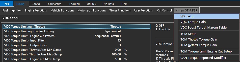
VDC Torque Limiting - Throttle
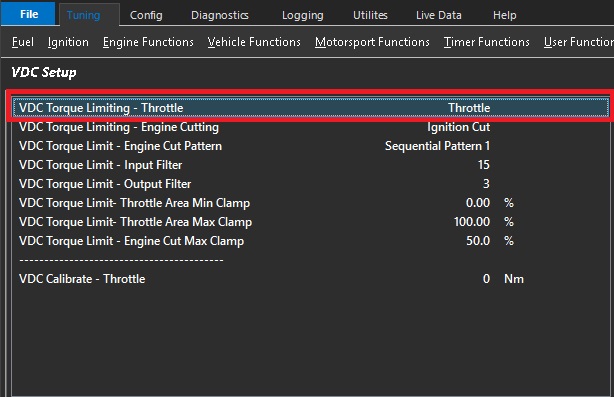
The VDC can request a Nm Torque Reduction/Limit using a combination of 2 methods:
Throttle Plate Area control (TMF)
Engine Cutting
These are separate requests sent over the CAN Bus from the VDC module to the ECU. The ECU then
uses a series of calculations to convert the Torque reduction request into either Throttle Plate position
or/and Engine Cut percentage.
The VDC primary Torque Limiting is done by using the Throttle Plate. The ECU uses Throttle Mass
Flow calculations to derive the required Throttle Area for a given Torque Target.
In some situations this may be insufficient to limit Engine Torque so a blend of Throttle Area
reduction and engine cutting maybe required.
CAUTION: When selected to OFF, the ECU will ignore the Torque Limit Throttle requests from the VDC module.
Default: Throttle.
0: OFF
1: Throttle
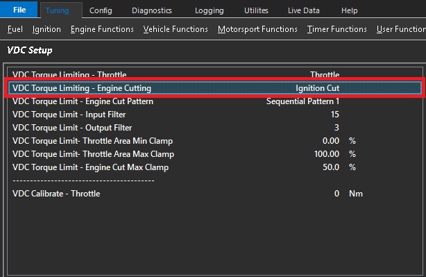
VDC Torque Limiting - Engine Cutting
The VDC can request a Nm Torque Reduction/Limit using a combination of 2 methods:
Throttle Plate Area control (TMF)
Engine Cutting
These are separate requests sent over the CAN Bus from the VDC module to the ECU. The ECU then
uses a series of calculations to convert the Torque reduction request into either Throttle Plate position
or/and Engine Cut percentage.
The VDC secondary Torque Limiting is done by Engine Cutting.
A VDC Torque Limit (Nm) using Engine Cutting gets converted by the ECU into a calibrated
Engine Cut percentage using the following parameters:
Engine Ideal Torque
Frictional Loss
Torque Reduction Cut Gain Table
CAUTION: When selected to OFF, the ECU will ignore the Torque Limit Cut requests from the VDC module.
Default: Ignition Cut.
0: OFF
1: Ignition Cut
2: Fuel Cut
3: Ignition + Fuel Cut
VDC Torque Limit - Engine Cut Pattern
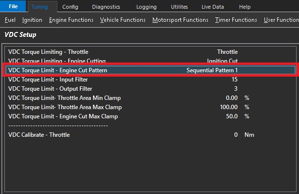
Used when VDC Torque Limiting is controlled with Engine Cutting.
Allows the cutting pattern to be selected.
All patterns will achieve the calculated torque and will simply affect the cylinder order of cutting.
Default: Sequential Pattern 1
0: Random Pattern 1
1: Random Pattern 2
2: Sequential Pattern 1
3: Sequential Pattern 2
VDC Torque Limit - Input Filter
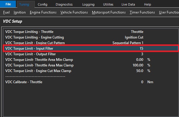
A VDC Torque Limit (Nm) gets converted by the ECU into a Throttle Area output called “Throttle Area Demand - VDC”.
The ECUs uses complex Throttle Mass Flow calculations which are influenced strongly by the Pressure Ratio inputs before
and after the throttle plate. This filter gets applied to this ratio and is used to smooth the input torque requests.
0 = OFF (more aggressive VDC Control)
15 = Max Filtering
VDC Torque Limit - Output Filter
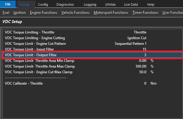
A VDC Torque Limit (Nm) gets converted by the ECU into a Throttle Area output called “Throttle Area Demand - VDC”.
The output (Throttle Area) can be filtered by adjusting this setting before its used to control the Throttle Plate Area.
0 = OFF (more aggressive VDC Control)
5 = Max Filtering
Plot “Throttle Area Demand %” (filtered value) vs “Throttle Area Demand - VDC” (raw unfiltered) for tuning and to see
the filtering effects.
This can be used to smooth the throttle area demand %.
Increasing the filter will smooth the throttle demand.
However it is important to understand that any filter will reduce the response of the system.
VDC Torque Limit- Throttle Area Min Clamp
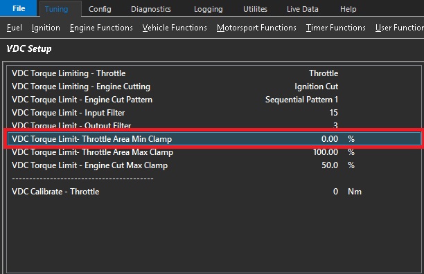
The VDC Torque Limit (Nm) with Throttle Plate control uses Throttle Mass
Flow calculations to derive the required Throttle Area for a given Torque Target.
This setting controls the Minimum amount of Throttle Area the ECU can apply for a given Torque Limit request.
0% = OFF
Example.: 60%
This means the Throttle Area is clamped between 60% and Max%
This is the minimum throttle area % that the system can apply during the VDC event.
Increasing this will cause the VDC system to favor more cutting to reduce torque to the request target.
An extreme of this setting would be 100% which means the throttle is not able to reduce.
VDC Torque Limit- Throttle Area Max Clamp
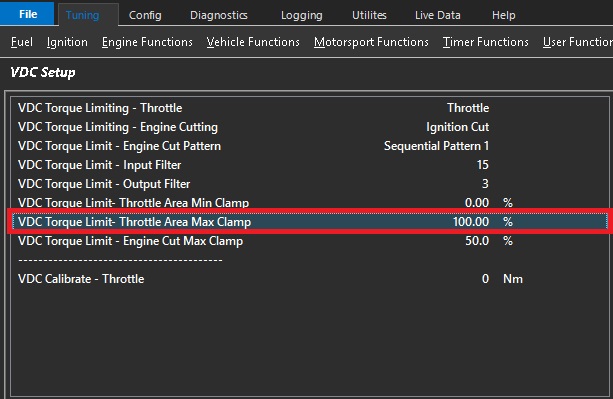
The VDC Torque Limit (Nm) with Throttle Plate control uses Throttle Mass
Flow calculations to derive the required Throttle Area for a given Torque Target.
This setting controls the Max amount of Throttle Area the ECU can apply for a given
Torque Limit request.
0% = OFF
Example.: 90%
This means the Throttle Area is clamped between Min% Value and 90%.
This should be set to 100% and require no adjustment in all known applications.
VDC Torque Limit - Engine Cut Max Clamp
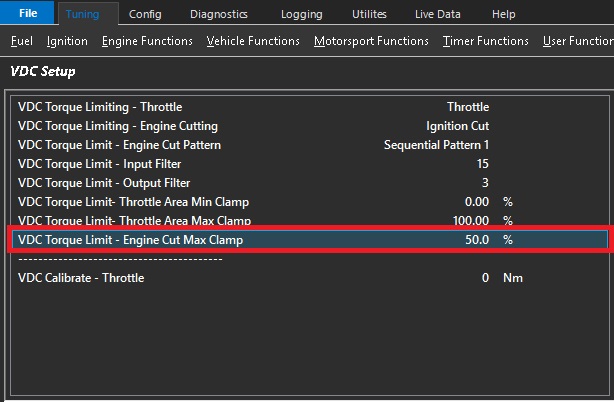
A VDC Torque Limit (Nm) using Engine Cutting gets converted by the ECU into a calibrated
Percentage
This setting controls the Maximum amount of Cut the ECU can apply for a given
Torque Limit request.
Example.: 50%
This means the Maximum Cut applied to the Engine will be clamped to 50%
This is set to 50% by default
Note: In situations where the torque is unable to meet the request target fast enough or at all, this setting would need to be increased. Lowering this setting will cause the VDC system to favor more throttle reduction.
VDC Calibrate - Throttle
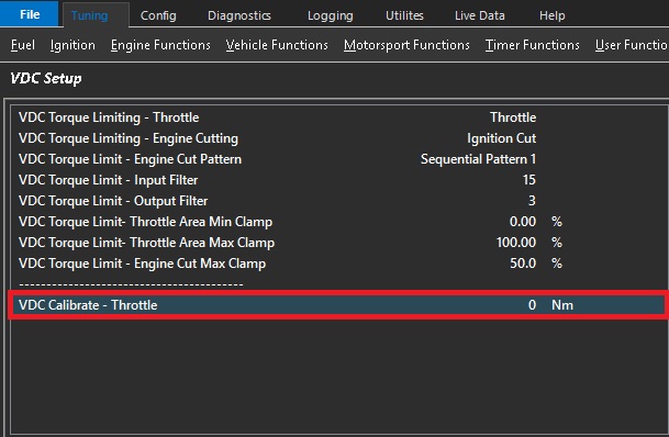
CAUTION The setting will override the Throttle Plate control and reduce the Throttle Area to achieve the entered Torque value.
The setting allows the VDC system to be calibrated and should be done so in a controlled environment only and preferably on a dynamometer.
ONLY becomes active when VDC Calibrate Throttle Area < Pedal Throttle Area Request
0 = OFF
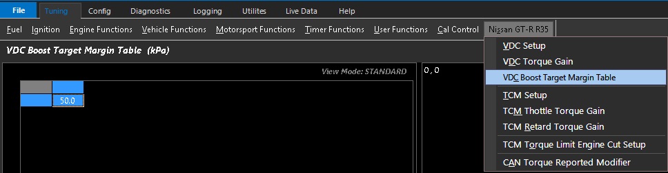
VDC Boost Target Margin Table
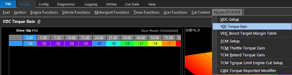
VDC Torque Gain
Nissan GTR R35 TCM Setup
TCM Setup
Nissan Transmission Control Module (TCM)
The transmission control module is responsible for anything related to the transmission.
The ECU does not control any part of the transmission,
However, it is responsible for obeying torque requests accurately which are sent to it via the CAN bus.
The ECU is responsible for reducing torque by closing the throttle and by retard.
Emtron has the ability to adjust torque requests requested by the TCM.
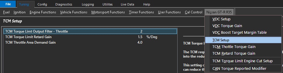
TCM Torque Limit Output Filter - Throttle
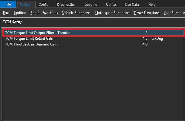
The TCM requests a Torque Limit (Nm) which gets converted by the ECU
into the reduced Throttle Area called “Throttle Area Demand - TCM”
This setting controls the rate at which the TCM Throttle Torque Limit
can reduce the Throttle Area Demand.
0 = OFF (more aggressive TCM Control)
5 = Max Filtering
Plot “Throttle Area Demand %” vs “Throttle Area Demand - VDC” for tuning.
TCM Torque Limit Retard Gain
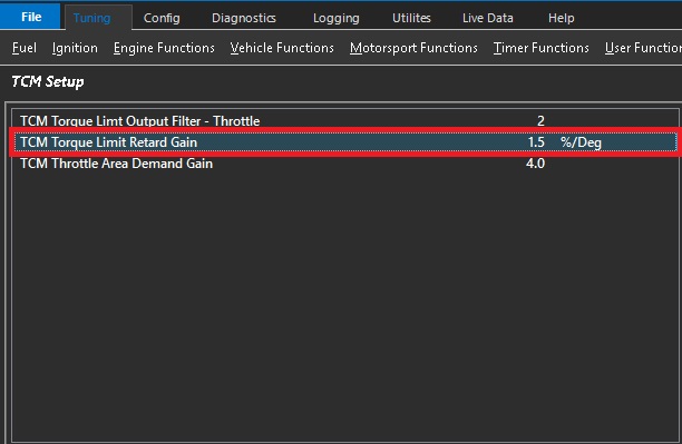
During a TCM Torque Reduction request the ECU can retard the timing to reduce Torque.
This setting indicates to the ECU the percentage of Torque reduced for every 1%/ Deg of Ignition Retard.
Example 1.5%/ Deg.
The Engine is running at 600Nm and a Torque
Reduction to 400Nm is requested.
This is a 33% reduction in Torque so at 1.5%/Deg
the ECU will Retard the Ignition 22 Degrees.
(33% / 1.5%/deg = 22 Deg)
TCM Throttle Area Demand Gain
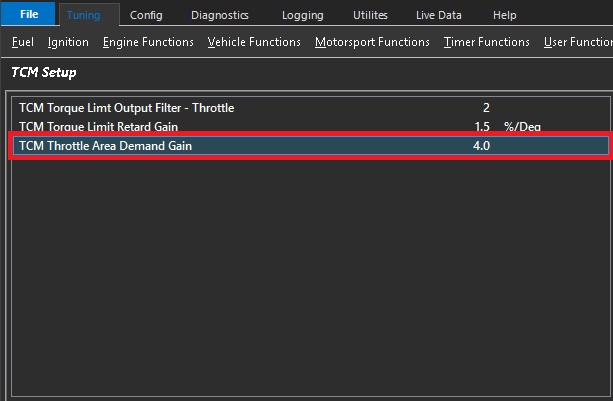
When the current Engine Torque is less than the TCM Torque Demand the Throttle Area will need to be increased.
To overcome inertia and other factors the plate needs to be momentary increased before it comes back to its calculated position.
This setting is primarily used in Launch Control to ensure the ECU tracks the TCM Torque Demand
Gain 0 = OFF
Gains up to the maximum of 5 can achieve good results.
TCM Retard Torque Gain
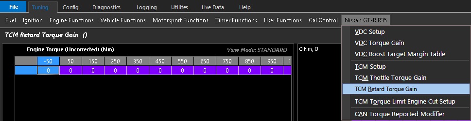
Nissan GTR R35 VDC Boost Target Margin Table
TCM Torque Limit Engine Cut Setup
TCM Torque Limit Engine Cut Setup
In some motorsport environments and extremely high-end applications the OEM Torque Reductions may not deliver maximum performance. This has been addressed by allowing the user the ability to leverage the factory torque requests and applying a cut for more instantaneous torque reduction.
This is particularly useful on gear shifts where sharper than factory shift response is required.
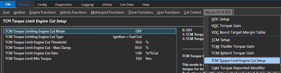
TCM Torque Limiting Engine Cut Mode
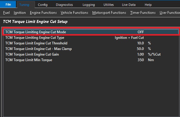
0: OFF
1: TCM Torque Limit Ref: Throttle
2: TCM Torque Limit Ref: Retard
This mode is used to assist the TCM and ECU in reducing the engines torque for improved gearshift control.
The primary source of Torque Reduction is throttle plate control and retard, but in situations of a large torque reduction, the addition of engine cutting can be used to help this process.
The TCM Sends torque limit requests using either Throttle or Retard.
Either torque value can be selected as the reference for the engine cutting calculation.
ONLY gets applied on the Up-shift
A minimum Engine Torque lockout is used to prevent the cut operating under light loads
TCM Torque Limiting Engine Cut Type
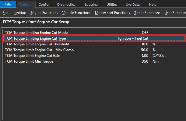
0: Ignition Cut
1: Fuel Cut
2: Ignition + Fuel Cut
TCM Torque Limit Engine Cut Threshold
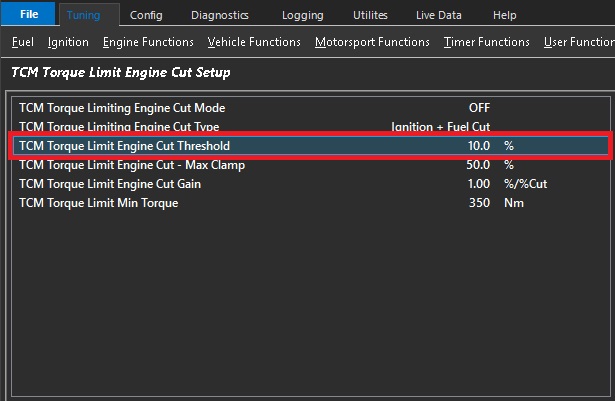
This mode is used to assist the TCM and ECU in reducing the engines torque for improved gearshift control.
The ECU converts the Torque Limit (Nm) sent by the TCM into a calibrated Engine Cut Percentage.
This setting controls the Torque Threshold above which Engine Cutting can be used to reduce torque
Example.:
Cut Threshold 10%
TCM Requesting Torque Limit of 300Nm.
Engine Torque 600Nm
10% of 300Nm = 330Nm
The ECU will calculate the required cut % from 600Nm down to 330Nm.
TCM Torque Limit Engine Cut - Max Clamp
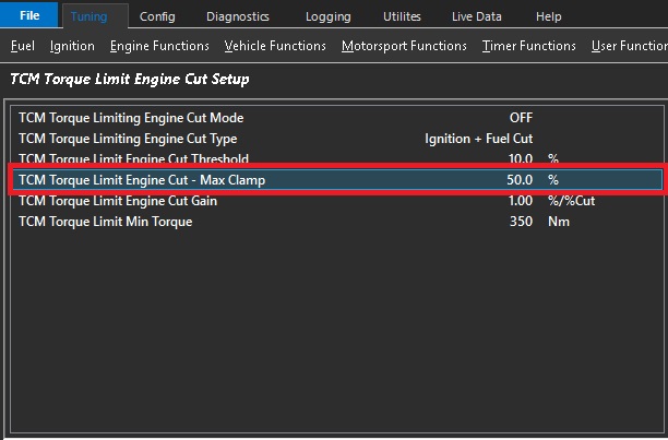
This mode is used to assist the TCM and ECU in reducing the engines torque for improved gearshift control.
The primary source of Torque Reduction is the closing of the throttle plate, but in situations of a large torque reduction,
Ignition cutting can be used to help this process.
The ECU converts the Torque Limit (Nm) into a calibrated Engine Cut Percentage.
This setting controls the Maximum amount of Cut the ECU can apply for a given Torque Limit request.
Example: 50%
This means the Maximum Cut applied to the Engine will be clamped to 50%.
TCM Torque Limit Engine Cut Gain
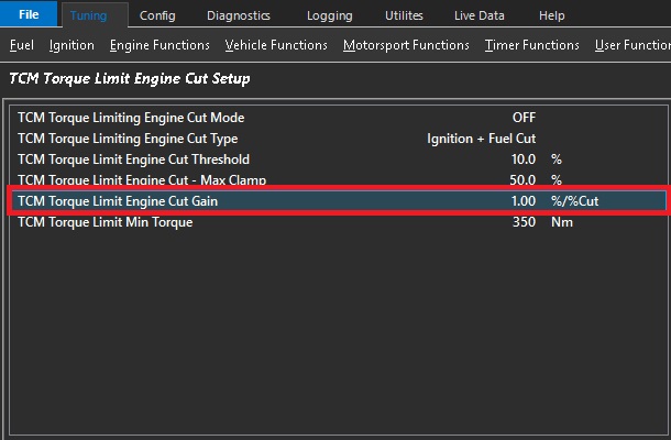
During a TCM Torque Reduction request the ECU can cut the engine to reduce Torque.
This setting indicates to the ECU the percentage of Torque reduced for every 1% of Engine Cut.
Example.
Engine Torque at 600Nm.
200Nm Torque Reduction is requested.
This is a 33% Reduction in Torque
1.0 %/ %Cut. ECU will cut engine at 33%
0.8 %/ %Cut. ECU will cut engine at 41%
1.2 %/ %Cut. ECU will cut engine at 27%
TCM Torque Limit Min Torque
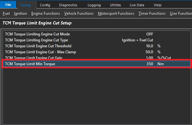
The Uncorrected Engine Torque must be greater than the entered value for the Engine Cut to be enabled
Nissan Patrol Y61
Nissan Patrol Y61 Application Build
1.0 Introduction
The Patrol Y61 Application Build is available for all Emtron ECUs. This build allows unique application-specific firmware to be installed into the ECU. The Y61 build includes:
- Full CAN Bus OEM integration for both Automatic and Manual Transmissions
- Y61 Gearshift control for automatic transmissions — controls and monitors the Engine Torque during the gearshift
- Emtron Nissan Y61 Base Calibration File
- Cruise Control (requires a DBW and Pedal Position sensor be fitted)
This build version requires Firmware Version 2.17.0 or later. Emtron will supply a recommended pinout configuration that matches the supplied calibration file.
2.0 Build Setup
The Y61 Build needs to first be purchased before it can be installed into the ECU. Each build purchase is locked to an ECU serial number, then available for installation from the Emtron online server.
2.1 Installation procedure
- Internet access is required for the build installation, allowing Emtune to access the Emtron online server.
- Connect Emtune to the ECU.
- Select the File → Build Management menu. A window will open and display all build options.
- Select the Y61 option which should be listed as INSTALL. Press OK.
- The installation process takes 5-10 seconds. A message box will confirm a successful installation.
- To verify the installation and view the status of all available builds, open the Runtime menu (F3) and select the “ECU Internal” tab.
2.2 Uninstall procedure
With internet access and Emtune connected, select File → Build Management, select the Y61 option (listed as UNINSTALL) and press OK. The uninstall process takes 5-10 seconds.
3.0 CAN Bus
The Y61 Base Calibration file is configured for OEM CAN Bus integration using CAN 2. It is highly recommended that no other CAN device(s) be connected to this Bus. Any additional CAN Bus IO expanding devices should be connected to CAN 1.
3.1 OEM CAN Bus – CAN 2
The ECU provides full integration with the OEM CAN bus, both receiving and transmitting data. Critical data like Engine Torque must be calibrated correctly as this is transmitted and used by other systems throughout the vehicle.
Once the build has been installed a “Patrol Y61” tab will be available in the Runtime menu (F3), providing application-specific data received over the CAN bus:
| ECU Input Channel Name | Description |
|---|---|
| Vehicle Speed | The average speed of the rear wheels |
| Input Shaft Speed | Input shaft speed of the transmission |
| Gear | Current gear reported by the transmission ECU |
| Gear Request | Current gear requested, reported by the transmission ECU |
| Upshift Request Switch | Upshift request reported by the transmission ECU |
| Downshift Request Switch | Downshift request reported by the transmission ECU |
| Cruise Control Switch | Cruise Control Off/On Switch |
ImportantIMPORTANT When wiring into the OEM CAN Bus a 120 Ohm CAN terminating resistor MUST be installed.
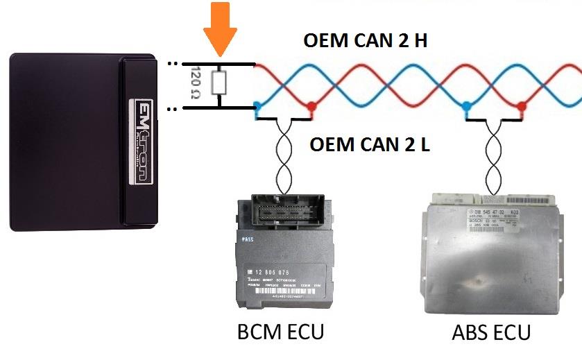
Figure 3.0 — OEM CAN Bus 120 Ohm CAN termination.
3.2 User CAN Bus – CAN 1
The following devices can be connected to the ECU CAN 1 inputs: ELC1/2 (Emtron Lambda to CAN), ETC4/ETC8M (Emtron Thermocouple to CAN), EIC10/EIC16M (Emtron Input to CAN). Standard CAN bus precautions apply — use twisted pair (min one twist per 40mm), minimise connectors, terminate with a 120 ohm 0.25W resistor at each END of the bus, and keep stub lengths under 0.3m (ISO 11898). All Emtron CAN devices have no on-board terminating resistor, allowing them to be wired at any position on the Bus.
4.0 Application Specific Functions
4.1 Gearshift Control Function Setup
The Nissan Patrol Y61 Application Build includes a special gearshift control feature specific to the vehicle (already enabled in the supplied build). To enable, go to Config → Functions → Function Output Setup → Motorsport functions → Gear Shift Control and select “Nissan Y61 – CAN BUS”.
4.2 Gearshift Control Function Tuning
Once enabled, the tuning view menu item “Gearshift Control Y61” is available. The ECU has no control over the actual shift points — this is handled by the OEM transmission control system. The ECU can only control torque during a gearshift request event, most commonly via a cut event or throttle reduction.
4.3 Gearshift Y61 Setup Menu
All gearshift torque reduction settings are calibrated here.
- Next Gear Stable Gear Position Source — The input source the ECU uses to consider the gearshift complete (cuts, throttle reductions and retards will be removed). Typical Setting: Gear Position – Input/Output shaft.
4.4 Up Shift Control Menu
4.41 Upshift Setup Menu
- Upshift Torque Reduction Cut Type — Cut type used for upshift torque reduction. Typical: Fuel + Ign Cut.
- Upshift Ign Retard Mode — How the ignition retard is calculated. Typical: Percentage.
- Upshift Torque Reduction Min Time — Minimum time a torque reduction can occur regardless of table configuration. Typical: 20ms.
- Upshift Throttle Override — A throttle override may be used to reduce torque, timed by either the function or a user duration. Typical: OFF.
- Upshift Rev-matching Limit — The ECU can calculate the engine speed required to match the transmission ratios using the output shaft speed and gear ratios. Typical: ON Outputshaft Speed Calculated.
- Upshift Rev-match Cut Type — The rev-matching function limits engine RPM to match the requested upshift gear, using output shaft RPM and transmission ratios. Typical: Ign Cut.
- NOTE 1: Output Shaft must be configured (Wheel Diameter and Final Drive ratios set correctly).
- NOTE 2: The Gear Ratio Table MUST be completed (Vehicle Functions → Vehicle Dynamics menu).
- NOTE 3: Rev-match RPM limiting should start AFTER the initial Torque Reduction Cut/Retard, otherwise the Rev-Match RPM limit (lower than current engine speed) takes %cut priority and prevents the initial reduction from working.
- Upshift Rev-match Control Range (-/+) — The engine speed range the ECU calculates the cut % over. Typical: 150rpm.
- Example: Rev-match RPM Target = 4700, Min Cut = 0%, Max Cut = 95%. Range +500 RPM → 4700 RPM = 0% Cut, 5300 RPM = 95% Cut. Range -500 RPM → 4700 RPM = 95% Cut, 4200 RPM = 0% Cut.
- Upshift Rev-match %Cut Clamp — Percentage cut applied to the engine at the end of the control range.
- Upshift Next Gear Timeout — The next gear must be reached within this time for the upshift to be valid; otherwise the ECU re-tries the gear shift per the “Upshift Re-retry Count” setting.
4.42–4.46 Torque Reduction Tables
- Torque Reduction Ign %Cut Level — Sets the ignition %cut level. The default table only provides a cut when torque levels are high, preventing cuts during normal driving.
- Torque Reduction Fuel %Cut Level — As above, for fuel %cut.
- Upshift Torque Reduction Retard — Controls the retard component of the torque reduction.
- Upshift Re-Match Enable Table — Controls when the torque reduction reverts from cut-table control to the rev-matching strategy.
- Upshift Re-Match RPM Target Correction — Ensures positive torque when on the throttle. Default is a global value of 20%.
4.47–4.411 Additional Upshift Settings
- Upshift DBW 1 Position — Not Used by Default.
- Upshift Throttle 1 Duration — Not Used by Default.
- Upshift Next Gear Torque Recovery Delay — Typical: 0ms.
- Upshift Next Gear %Cut Level Recovery Delay — Typical: 0ms.
- Upshift Next Gear Ignition Recovery Time — Typical: 0ms.
4.5 Down Shift Control Menu
There is no implementation of this feature at the time of writing.
5.0 Cruise Control
5.1 OEM Cruise Control
The Nissan Patrol Y61 comes fitted with OEM cruise control. A cable is actuated by the cruise control module and overrides the electronic throttle. The ECU has no control over this function and it will operate as normal if the factory throttle body is fitted.
5.2 Emtron Cruise Control
If the factory throttle body is replaced with an aftermarket unit there is no way for the OEM cruise control to operate. Modern DBW throttle bodies will require a custom fitment of a pedal position sensor. Emtron has a special channel for the factory cruise control buttons which is decoded so they may be used with the Emtron Cruise Control feature.
5.21 Emtron Cruise Control Application Build — The Y61 build already has the Emtron Cruise Control function enabled if using firmware V2.17.0 or later. See the Cruise Control build for detailed tuning information.
5.22 Nissan Patrol Y61 Cruise Command Switch — The Factory Cruise Command Switch only requires one wire to be spliced and pinned into the ECU. Any spare Analog Volt or Digital Input may be allocated for this switch. Once pinned in, configure the channel by selecting only the ECU pin (e.g. ANV 10) — no further input configuration is required. To test, press F3 to open the ECU Runtimes form and confirm each button changes state when pressed.
6.0 ECU Channel Assignment
Injection
| ECU Channel | Function |
|---|---|
| Injection 1-6 | Fuel Injector Cyl 1-6 |
| Injection 7 | AC Clutch Relay |
| Injection 8 | Tachometer |
| Injection 9-12 | Not Used |
Ignition
| ECU Channel | Function |
|---|---|
| Ignition 1-6 | Ignition Cyl 1-6 |
| Ignition 7-12 | Not Used |
Analog Inputs
| ECU Channel | Function |
|---|---|
| Analog Voltage 1 | MAP |
| Analog Voltage 2 | DBW Servo Position Main |
| Analog Voltage 3 | DBW Servo Position Sub |
| Analog Voltage 4 | Pedal Position (Main) |
| Analog Voltage 5 | Pedal Position (Sub) |
| Analog Voltage 6 | Not Used |
| Analog Voltage 7 (Pull-up) | Engine Temperature |
| Analog Voltage 8 (Pull-up) | Inlet Air Temperature |
| Analog Voltage 9 (Pull-up) | Mass Air Flow Sensor |
| Analog Voltage 10 (Pull-up) | *Cruise Command Switch (Y61) |
| Analog Voltage 11-12 (Pull-up) | Not Used |
| Analog Voltage 13-14 | Not Used |
Analog Voltage Channels 7-12 have switchable pull-ups suitable for temperature measurement. *Cruise Command Switch used when replacing the throttle body with an aftermarket unit.
Digital Inputs
| ECU Channel | Function |
|---|---|
| Digital Input 4 | Power Steer Switch |
| Digital Input 6 | Snow Switch |
| Others | Not Used |
Auxiliary Outputs
| ECU Channel | Function |
|---|---|
| Auxiliary 1 | CAM Switch Solenoid |
| Auxiliary 2 | User Output 1 – Manifold Flap |
| Auxiliary 3 | Engine Fan Relay |
| Auxiliary 4 | Fuel Pump Relay |
| Auxiliary 9 | DBW + |
| Auxiliary 10 | DBW - |
| Others | Not Used |
Crank / Cam
| ECU Channel | Function |
|---|---|
| Crank Index | Crank Sensor |
| Sync Sensor | Cam Position Sensor |
CAN
| ECU Channel | Function |
|---|---|
| CAN 1 Lo/Hi | User CAN Bus Lo/Hi |
| CAN 2 Lo/Hi | OEM CAN Bus Lo/Hi |
OEM CAN Inputs
AC Switch, Brake Switch 1, Cruise Enable, Drive Speed, Input Shaft Speed, Gear Upshift Switch, Gear Downshift Switch.
7.0 Y61 ECU Pinout
| OEM Pin | Function | ECU Channel |
|---|---|---|
| 5 | Injector Cylinder 1 | Injector 1 |
| 6 | Injector Cylinder 2 | Injector 2 |
| 7 | Injector Cylinder 3 | Injector 3 |
| 13 | Injector Cylinder 4 | Injector 4 |
| 14 | Injector Cylinder 5 | Injector 5 |
| 15 | Injector Cylinder 6 | Injector 6 |
| 18 | Ignition Cylinder 1 | Ignition 1 |
| 19 | Ignition Cylinder 2 | Ignition 2 |
| 20 | Ignition Cylinder 3 | Ignition 3 |
| 21 | Ignition Cylinder 4 | Ignition 4 |
| 24 | AC Clutch | Injector 7 |
| 27 | Inlet Manifold Flap | Aux 2 |
| 29 | Ignition Cylinder 5 | Ignition 5 |
| 30 | Ignition Cylinder 6 | Ignition 6 |
| 38 | Tachometer | Injector 8 |
| 40 | Fuel Pump | Aux 4 |
| 42 | EFI Relay Control | EFI Relay |
| 48 | Idle Stepper | Aux 5 |
| 49 | Idle Stepper | Aux 7 |
| 50 | Idle Stepper | Aux 6 |
| 51 | Idle Stepper | Aux 8 |
| 52 | Speed Sensor | DI 1 |
| 53 | Ignition Switch | IGN Switch |
| 55 | Cooling Fan | Aux 3 |
| 60 | Snow Switch | DI 6 |
| 63 | Engine Speed Sensor | Crank Index +ve |
| 79 | Steering Pressure Switch | DI 4 |
| 84 | Engine Sync Sensor | Sync Index +ve |
| 86 | AC Request | DI 5 |
| 87 | Pedal Position Sensor Main | AN 4 |
| 89 | Sensor Ground | Sensor 0V Ref |
| 94 | +5V Supply | 5.0V VRef1 |
| 98 | Throttle Servo Sub | AN 3 |
| 100 | Sensor Ground | Sensor 0V Ref |
| 108 | Throttle Servo Main | AN 2 |
| 109 | Sensor Ground | Sensor 0V Ref |
| 117 | Pedal Position Sensor Sub | AN 5 |
| 121 | Coolant Temp Sensor | AN 7 |
| 125 | Knock Sensor Rear +ve | Knock Sensor 2 +ve |
| 126 | Knock Sensor Front +ve | Knock Sensor 1 +ve |
| 151 | Throttle Motor +ve *(Auto Only) | Aux 9 |
| 152 | Inlet Cam Actuator | Aux 1 |
| 153 | Ground | Ground |
| 154 | Throttle Motor -ve *(Auto Only) | Aux 10 |
| 156 | Ground | Ground |
| 158 | Ground | Ground |
| 159 | Ground | Ground |
| 163 | ECU Supply | Aux 9-10 Supply / ECU Supply |
| 165 | Ground | Ground |
| 166 | ECU Supply | Aux 9-10 Supply / ECU Supply |
| 168 | Ground | Ground |
| 171 | OEM CAN LO | CAN 1 LO |
| 174 | OEM CAN HI | CAN 1 HI |
Nissan R32-R34
Nissan R32-R34 Plug-in ECU User Manual
1.0 Introduction
The Nissan R32-R34 ECU is designed to be plugged into the OEM harness to allow for a true “Plug and Play” install. The system is based on the KV Series Motorsport ECU, so all the same features are available excluding any limitations based around the OEM connector system. An Expansion port is included giving access to unused Input channels. CAN Bus 1 is also available providing additional I/O expandability.
2.0 Plugin Features
General
- KV8 ECU based platform — Dual 100MHz processors, 32MB ECU logging memory, over 1000 logging channels, 1Hz to 500Hz logging rate
- Aluminium 6061 Grade CNC billet enclosure
- Compatible with all Emtron proven motorsport features (Launch Control, Rolling Launch, Anti-Lag, Traction Control)
- Upgradeable to run the Emtron fuel model through installation of a flex meter, fuel temperature and fuel pressure sensor
- Idle speed closed loop control using DBW with advanced Throttle Mass Flow (TMF) airflow calculations
- Knock control with high speed digital filtering for each cylinder using the OEM sensor with selectable centre frequency and bandwidth
- Pre-configured calibration file loaded providing a comprehensive tuning platform
- Input Expansion Capabilities through DTM connector: 3× User Analog Volt Inputs (Fuel Temperature, Fuel Pressure, Inlet Temperature), 1× User Digital Input (Flex Meter Input and switch inputs), 2× User Analog Inputs
- Emtune software for tuning and data analysis
Communications: CAN 2.0B Bus 1 (User CAN Bus for I/O expansion — Lambda, EGT); High Speed Ethernet 100Mbps for tuning software connection.
Operating Temperature: -30 to 85°C (-22 to 185°F)
Physical: Enclosure Size 160 × 162 × 38 mm, 890g
3.0 Installation
3.1 Expansion Port
The ECU’s input capabilities can be expanded using the expansion connection, which is a male DTM 12 Way. These additional inputs can be connected to any sensor, but the recommended sensors are indicated in brackets.
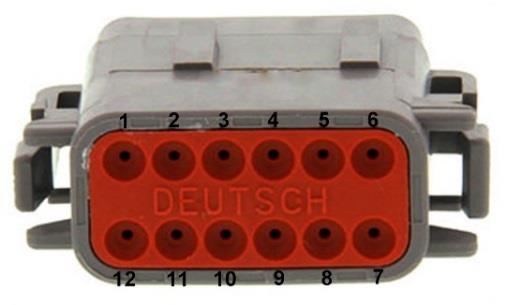
Nissan R32-R34 expansion port connector (DTM 12-way).
Table 3.0 — Expansion Port Pinout (DTM06-12SA)
| Pin | Function |
|---|---|
| 1 | Analog Sensor 0V Reference |
| 2 | 5V Vref2 Supply |
| 3 | AN 8 (e.g. Fuel Temp or Inlet Temp) |
| 4 | AN 9 (e.g. Fuel Temp or Inlet Temp) |
| 5 | AN 10 (e.g. Fuel Pressure) |
| 6 | DI 6 (e.g. Ethanol Content Sensor) |
| 7 | ANV 13 |
| 8 | ANV 14 |
| 9 | 14V Out Protected (e.g. ELC2 Power Supply) |
| 10 | ECU Ground (e.g. ELC2 or E85 Sensor Ground) |
| 11 | CAN 1 Hi |
| 12 | CAN 1 Lo |
3.2 CAN Bus 1 Wiring
The ECU CAN Bus 1 is reserved for Emtron CAN Bus devices, expanding the IO capability of the ECU. The following devices can be connected: ELC1/2 (Lambda to CAN), ETC4/ETC8M (Thermocouple to CAN), EIC10/EIC16M (Input to CAN). All these CAN devices share a common power, ground and CAN pinout using a 4-way DTM.
Table 3.1 — CAN Device Power and CAN Deutsch Connector Pinout
| Pin | Function | Wire Colour |
|---|---|---|
| 1 | Ground | BLACK |
| 2 | CAN Lo | GREEN |
| 3 | CAN Hi | YELLOW |
| 4 | 12V Supply | RED |
To help with installation time, each CAN Device pin can be directly connected into the ECU IO Expansion port:
Table 3.2 — IO Expansion to CAN Device wiring
| Name | ECU IO Expansion 12-Way DTM | CAN Device 4-Way DTM |
|---|---|---|
| Ground | Pin 8 | Pin 1 |
| CAN 1 Lo | Pin 12 | Pin 2 |
| CAN 1 Hi | Pin 11 | Pin 3 |
| Power | Pin 7 | Pin 4 |
Standard CAN bus precautions apply — twisted pair (min one twist per 40mm), minimise connectors, 120 ohm 0.25W termination at each END, stub length < 0.3m (ISO 11898). All Emtron CAN devices have no on-board terminating resistor, allowing them to be wired at any position on the Bus.
3.3 Analog Sensor Wiring
5V VRef2 Sensor Supply (Pin 2 of Expansion port) — A 250mA 5V output designed to supply automotive sensors.
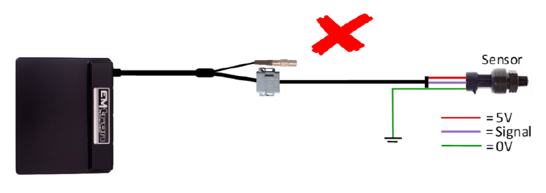
Sensor 0V Reference (Pin 1 of Expansion port) — This pin should be connected directly to the 0V (Ground) pin on any low current analog sensor, for example Pressure or Temperature.
- DO NOT connect the 0V Reference pin directly to the Engine Block or ECU Ground. This is a dedicated and specialised 0V/ground output for analog sensors.
- DO NOT connect frequency-based sensor grounds to the 0V Reference pin; for example, an Ethanol content sensor. Use Pin 8 (Ground) in the Expansion port.
Figure 3.3 — Correct Pressure Sensor 0V wiring (direct to the Sensor 0V Reference). Figure 3.4 — Incorrect Pressure Sensor 0V wiring.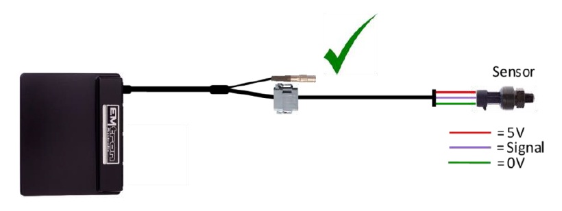
3.4 Ethanol Content Sensor Wiring
An Ethanol Content sensor can be wired into the ECU using the Expansion port. The following channel assignment is recommended for the GM sensor:
| GM Sensor Pinout | Expansion Port | Description |
|---|---|---|
| Pin 1 | Pin 9 — 14V Protected | Supply, 8V or 14V |
| Pin 2 | Pin 10 — ECU Ground | Ground |
| Pin 3 | Pin 6 — DI 6 | Output. Temperature and Ethanol Content |
NoteNOTE DO NOT connect the Ethanol Content sensor ground to the “Analog Sensor 0V Reference” — use the ECU Ground from Pin 10. The Ethanol sensor produces a frequency-based output; suitable ECU channels are DI 1-8.
| Description | Calibration |
|---|---|
| Ethanol Content (%) | 50Hz = 0% Ethanol, 150Hz = 100% Ethanol |
| Fuel Temperature | 1ms = -40°C, 5ms = 125°C |
To configure the ECU for this sensor, select the Ethanol Sensor Input Source to DI6. The ECU will automatically decode the Ethanol Content and Fuel Temperature. Once assigned, more settings become available in the Tuning View → Engine Functions menu.
4.0 ECU Channel Assignment
Injection
| ECU Channel | Function |
|---|---|
| Injection 1-6 | Fuel Injector Cyl 1-6 |
| Injection 7 | O2 Heater |
| Injection 8-12 | Not Used |
Ignition
| ECU Channel | Function |
|---|---|
| Ignition 1-6 | Ignition Cylinder 1-6 |
| Ignition 7 | FPCM1 |
| Ignition 8 | FPCM1 |
| Ignition 9 | Trigger Sensor 120/1 Control |
| Ignition 10-12 | Not Used |
Analog Inputs
| ECU Channel | Function |
|---|---|
| Analog Voltage 1 | TPS |
| Analog Voltage 2 | O2 Front |
| Analog Voltage 3 | O2 Rear |
| Analog Voltage 4 | MAF (Rear R32) |
| Analog Voltage 5 | MAF Front R32 |
| Analog Voltage 6 | Not Used |
| Analog Voltage 7 (Pull-up) | Engine Temperature |
| Analog Voltage 8-10 (Pull-up) | IO Expansion port |
| Analog Voltage 11-12 (Pull-up) | Not Used |
| Analog Voltage 13-14 | Not Used |
Analog Voltage Channels 7-12 have switchable pull-ups suitable for temperature measurement.
Digital Inputs
| ECU Channel | Function |
|---|---|
| Digital Input 1 | Vehicle Speed |
| Digital Input 2 | Neutral Switch |
| Digital Input 3 | Start Switch |
| Digital Input 4 | AC Request Switch |
| Digital Input 5 | Alternator FR Signal |
| Digital Input 6 | IO Expansion port (Ethanol Sensor) |
| Digital Input 7 | Power Steer Pressure Switch |
| Digital Input 8-14 | Not Used |
Auxiliary Outputs
| ECU Channel | Function |
|---|---|
| Auxiliary 1 | VTC Solenoid |
| Auxiliary 2 | Wastegate Solenoid |
| Auxiliary 3 | Tacho |
| Auxiliary 4 | ISC Solenoid |
| Auxiliary 5 | Fuel Pump Relay |
| Auxiliary 6 | A/C Clutch Relay |
| Auxiliary 7 | CE Light |
| Auxiliary 8 | Fan Relay (R32) |
| Auxiliary 9 | EGT Light (R33) |
| Auxiliary 10 | Injector %DC Display |
| Auxiliary 11 | Connected to pin 111 (user output – 5A) |
| Auxiliary 12 | Connected to pin 112 (user output – 5A) |
| Auxiliary 13-16 | Not Used |
Crank / Cam
| ECU Channel | Function |
|---|---|
| Crank Index | Crank Position Sensor (120 Deg) |
| Sync Sensor | Crank Position Sensor (1 Deg) |
5.0 Plug-in Specific Information
5.1 Fuel Model
The ECU has the ability of using any Emtron-based Fuel Model; however, the base calibration provided implements a simple version of Speed Density. The Main VE Table has the Efficiency Calculation configured to span against TPS, which simplifies the mapping process. The fuel calculation will still account for Inlet Manifold Pressure. The Lambda Target is modified by a combination of Engine Speed and Manifold Pressure in the base calibration and allows for increasing enrichment based on an increase in engine load.
5.2 Inlet Air Temperature
Factory Inlet Air Temperature using ECU input ANV 8 is available on most models. If the input shows 4.85V or higher, this sensor is not connected and will need to be fitted and wired in using the Expansion port (refer to section 3.1).
5.3 ECU User Pins 111, 102
ECU pins 111 and 102 are unused OEM pins which connect directly to Aux 11 and 12 respectively. These are Half Bridge drivers rated at 5A continuous and 8A limit, and can be used as Low Side, High Side or together for DC motor control.
5.3 EGT Light
The R33 models have an EGT Light on Auxiliary 9. This can be configured and controlled from a User Channel.
5.4 Crank (120) and Crank (1) Signal Selection
For correct engine decoding, the ECU Crank Index input should be connected to the Nissan 120 degree signal and the Sync input connected to the Nissan 1 degree signal. The R32 and R33 should not require the signal swap enabled. The R34 will require the enabling of the Crank (120) and Crank (1) signal swap, which will otherwise prevent the engine from starting (cranking RPM will read extremely high if the pin swap is not enabled). These signals can be swapped using internal circuitry controlled by Ignition 9 — it doesn’t require any physical pins to be swapped. A User channel can be configured to control this.
Table 5.0 — Ignition 9 Crank Signal Configuration
| ECU Pin | Ignition 9 OFF | Ignition 9 ON |
|---|---|---|
| Pin 41/51 | Crank Signal 120 degree | Crank Signal 1 Degree |
| Pin 42/52 | Crank Signal 1 Degree | Crank Signal 120 degree |
6.0 Diagnostic Trouble Codes (DTCs)
On initial installation it is advised to clear all the DTCs if errors are reported. Connect to Emtune and look at the DTC status in the bottom toolbar (red if errors are present). Open the DTC window via the DTC Status box or File → Open DTC, select “Clear ALL DTCs”, and confirm all the Error Codes have been removed (status box goes green). If the error codes have not all been removed, select “Update DTC” then use the DTC window to locate the sensor that is on fault.
7.0 Ordering Information
| Product | Part Number |
|---|---|
| Emtron Nissan R32-R34 Plugin | 1609-1834 |
| Emtron Ethernet Tuning Cable (1.5m) | 553-15 |
Appendix A – Nissan R32-R34 ECU Pinout
| Pin | Function | Channel Assignment |
|---|---|---|
| 1 | Ignition 1 | IGN 1 |
| 2 | Ignition 5 | IGN 5 |
| 3 | Ignition 3 | IGN 3 |
| 4 | Idle Speed Control Solenoid | AUX 4 |
| 5 | AT Shift Request | DI 5 |
| 6 | Engine Fan Relay (R32) | AUX 8 |
| 7 | Tacho | AUX 3 |
| 8 | Ignition Switch (some models only) | Ignition Switch |
| 9 | A/C Clutch Relay | AUX 6 |
| 10 | Ignition Ground | ECU GROUND |
| 11 | Ignition 6 | IGN 6 |
| 12 | Ignition 2 | IGN 2 |
| 13 | Ignition 4 | IGN 4 |
| 16 | ECCS Relay | EFI RELAY |
| 17 | Injector %DC Display (or E85) | AUX 10 |
| 18 | Fuel Pump Relay | AUX 5 |
| 19 | Power Steer Pressure Switch | DI 7 |
| 20 | Ignition Ground | ECU GROUND |
| 23 | Knock Sensor 1 | Knock 1+ |
| 24 | Knock Sensor 2 | Knock 2+ |
| 25 | Wastegate Solenoid | AUX 2 |
| 26 | MAF Ground | ECU GROUND |
| 27 | Mass Air Flow Sensor (Rear) | ANV 4 |
| 28 | Engine Coolant Temperature | ANV 7 |
| 29 | O2 Sensor Front | ANV 2 |
| 30 | Sensor Ground (Coolant, O2) | Sensor 0V Reference |
| 31 | Clock (Sync Signal) | |
| 32 | CE Light | AUX 7 |
| 33 | EGT Light (R33) | AUX 9 |
| 34 | MAF Ground | ECU GROUND |
| 35 | Mass Air Flow Sensor (Front) | ANV 5 |
| 36 | Inlet Air Temperature (some models only) | ANV 8 |
| 38 | Throttle Closed Switch | ANV 1 |
| 40 | Sensor Ground (MAP, TPS) | Sensor 0V Reference |
| 41 | Crank Position Sensor (120) | Crank Index |
| 42 | Crank Position Sensor (1) | Sync Sensor |
| 43 | Start Switch | DI 3 |
| 44 | Neutral Switch | DI 2 |
| 45 | Ignition Switch | Ignition Switch |
| 46 | A/C Request Switch | DI 4 |
| 48 | TPS +5V Supply | + 5V Supply |
| 49 | Control Unit Power Supply | ECU SUPPLY |
| 50 | Control Unit Ground | ECU GROUND |
| 51 | Crank Position Sensor (120) | Crank Index |
| 52 | Crank Position Sensor (1) | Sync Sensor |
| 53 | Vehicle Speed Sensor | DI 1 |
| 55 | O2 Sensor Rear | ANV 3 |
| 56 | Throttle Position Out | AV OUT 1 |
| 58 | Battery Backup (+12 Constant) | Internal Flywheel Supply |
| 59 | Control Unit Power Supply | ECU SUPPLY |
| 60 | Control Unit Ground | ECU GROUND |
| 101 | Injector 1 | INJ 1 |
| 102 | (N/C — user output) | AUX 12 |
| 103 | Injector 3 | INJ 3 |
| 104 | Fuel Pump Control #1 | IGN 7 |
| 105 | Injector 2 | INJ 2 |
| 106 | Fuel Pump Control #2 | IGN 8 |
| 107 | Injector Ground | ECU GROUND |
| 108 | Injector Ground | ECU GROUND |
| 110 | Injector 5 | INJ 5 |
| 111 | (N/C — user output) | AUX 11 |
| 112 | Injector 6 | INJ 6 |
| 113 | VTC Solenoid (R33) | AUX 1 |
| 114 | Injector 4 | INJ 4 |
| 115 | O2 Heater Rear (R33/R34) | INJ 7 |
| 116 | Injector Ground | ECU GROUND |
Subaru STi/WRX 06-15
Subaru STi/WRX 06-15 Plug-in ECU User Manual
1.0 Introduction
The Subaru STi MY06-07 and Subaru MY08-15 Plugin ECUs are designed to be plugged into the OEM harness to allow for a true “Plug and Play” install. Both models are almost identical; however, purchase of the correct unit for your model is essential to ensure correct operation. The unit is also compatible with the WRX throughout MY06-07 and MY08-15. Field testing indicates the ECU will also work on MY16-MY17 models, however full support has not been confirmed at the time of writing.
The system is based on the KV Series Motorsport ECU, so all the same features are available with the limitation based around the OEM connector system. An Expansion loom is included giving access to unused Input channels. CAN Bus 2 is also available, operating independently to the OEM Bus, providing additional I/O expandability.
2.0 Plugin Features
General
- KV8 ECU based platform — Dual 100MHz processors, 32MB ECU logging memory, over 1000 channels, 1Hz to 500Hz logging rate
- Aluminium 6061 Grade CNC billet enclosure
- Fully compatible with all OEM systems and user programmable
- Compatible with all Emtron proven motorsport features (Launch Control, Rolling Launch, Anti-Lag, Traction Control)
- Upgradeable to run the Emtron fuel model through installation of a flex meter, fuel temperature and fuel pressure sensor
- Idle speed closed loop control using DBW with advanced Throttle Mass Flow (TMF) airflow calculations
- Knock control with high speed digital filtering for each cylinder using the OEM sensor with selectable centre frequency and bandwidth
- Pre-configured calibration file loaded providing a comprehensive tuning platform
- Input Expansion Capabilities through DTM connector: 3× User Analog Volt Inputs (Fuel Temperature, Fuel Pressure, Inlet Temperature), 1× User Digital Input (Flex Meter Input)
- Emtune software for tuning and data analysis
Communications: CAN 2.0B Node 1 — 500k Baud Full CAN Bus OEM Integration (ABS, SI Drive, DCCD); CAN 2.0B Node 2 — User CAN Bus for I/O expansion (Lambda, EGT); High Speed Ethernet 100Mbps.
Operating Temperature: -30 to 85°C (-22 to 185°F)
Physical: Enclosure Size 160 × 162 × 38 mm, 890g
3.0 Installation
3.1 Expansion Loom
The ECU’s input capabilities can be expanded using the expansion connection, which is a male DTM 12 Way. These additional inputs can be connected to any sensor, but the recommended sensors are indicated in brackets.
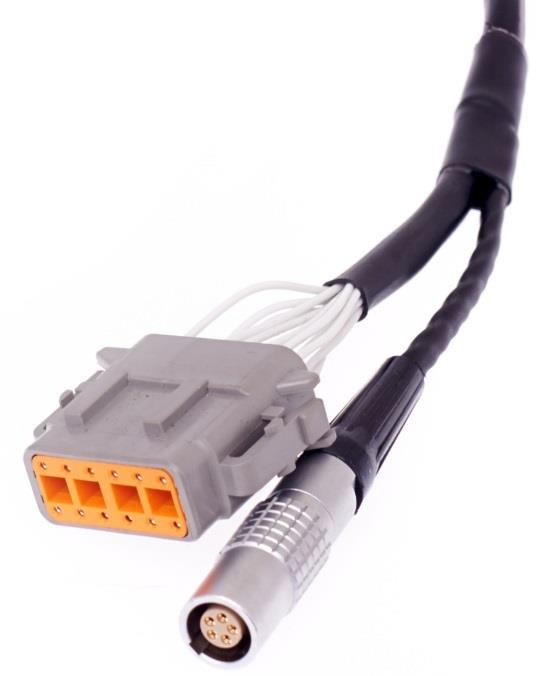
Figure 3.0 — DTM 12 Way expansion loom connector (ECU side).
Table 3.0 — Expansion Port Pinout (DTM06-12SA)
| Pin | Function |
|---|---|
| 1 | Analog Sensor 0V Reference |
| 2 | 5V Vref2 Supply |
| 3 | AN 8 (e.g. Fuel Temp or Inlet Temp) |
| 4 | AN 9 (e.g. Fuel Temp or Inlet Temp) |
| 5 | AN 10 (e.g. Fuel Pressure) |
| 6 | DI 6 (e.g. Ethanol Content Sensor) |
| 7 | 14V Out Protected (e.g. ELC2 Power Supply) |
| 8 | Ground (e.g. ELC2 or E85 Sensor Ground) |
| 9 | Not Used |
| 10 | Not Used |
| 11 | CAN 2 Hi |
| 12 | CAN 2 Lo |
3.2 CAN Bus 2 Wiring
The ECU CAN Bus 2 is reserved for Emtron CAN Bus devices, expanding the IO capability of the ECU. The following devices can be connected: ELC1/2 (Lambda to CAN), ETC4/ETC8M (Thermocouple to CAN), EIC10/EIC16M (Input to CAN).
NoteNOTE ECU CAN Bus 2 operates independently to the OEM CAN Bus 1.
Table 3.1 — CAN Device Power and CAN Deutsch Connector Pinout
| Pin | Function | Wire Colour |
|---|---|---|
| 1 | Ground | BLACK |
| 2 | CAN Lo | GREEN |
| 3 | CAN Hi | YELLOW |
| 4 | 12V Supply | RED |
To help with installation time, each CAN Device pin can be directly connected into the ECU IO Expansion loom:
Table 3.2 — IO Expansion to CAN Device wiring
| Name | ECU IO Expansion 12-Way DTM | CAN Device 4-Way DTM |
|---|---|---|
| Ground | Pin 8 | Pin 1 |
| CAN 2 Lo | Pin 12 | Pin 2 |
| CAN 2 Hi | Pin 11 | Pin 3 |
| Power | Pin 7 | Pin 4 |
Standard CAN bus precautions apply — twisted pair (min one twist per 40mm), minimise connectors, 120 ohm 0.25W termination at each END, stub length < 0.3m (ISO 11898). All Emtron CAN devices have no on-board terminating resistor, allowing them to be wired at any position on the Bus.
3.3 Sensor Wiring
5V VRef2 Sensor Supply (Pin 2 of Expansion loom) — A 250mA 5V output designed to supply automotive sensors.
Sensor 0V Reference (Pin 1 of Expansion loom) — This pin should be connected directly to the 0V (Ground) pin on any low current analog sensor, for example Pressure or Temperature.
- DO NOT connect the 0V Reference pin directly to the Engine Block or ECU Ground. This is a dedicated and specialised 0V/ground output for analog sensors.
- DO NOT connect frequency-based sensor grounds to the 0V Reference pin; for example, an Ethanol content sensor. Use Pin 8 (Ground) in the Expansion Loom.
Figure 3.3 — Correct Pressure Sensor 0V wiring (direct to the Sensor 0V Reference). Figure 3.4 — Incorrect Pressure Sensor 0V wiring.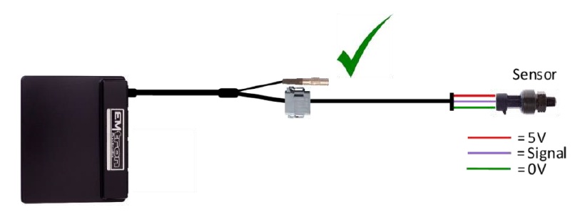
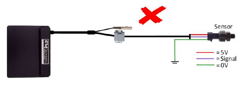
4.0 ECU Channel Assignment
Injection
| ECU Channel | Function |
|---|---|
| Injection 1-4 | Fuel Injector Cyl 1-4 |
| Injection 5 | Rear Lambda Heater |
| Injection 6 | DBW Relay |
| Injection 7 | Purge Solenoid 1 |
| Injection 8-12 | Not Used |
Ignition
| ECU Channel | Function |
|---|---|
| Ignition 1-4 | Ignition Cylinder 1-4 |
| Ignition 5 | Alternator Load Control |
| Ignition 6 | AC Fan Relay |
| Ignition 7 | Engine Fan Relay |
| Ignition 8 | AC Clutch Relay |
| Ignition 9-12 | Not Used |
Analog Inputs
| ECU Channel | Function |
|---|---|
| Analog Voltage 1 | MAP |
| Analog Voltage 2 | TPS (Main) |
| Analog Voltage 3 | TPS (Sub) |
| Analog Voltage 4 | MAF |
| Analog Voltage 5 | O2 Rear Narrow Band |
| Analog Voltage 6 | TGV RH Position |
| Analog Voltage 7 (Pull-up) | Engine Temperature |
| Analog Voltage 8 (Pull-up) | IO Expansion loom (Inlet Temperature) |
| Analog Voltage 9 (Pull-up) | IO Expansion loom (Fuel Temperature) |
| Analog Voltage 10 (Pull-up) | IO Expansion loom (Fuel Pressure) |
| Analog Voltage 11 (Pull-up) | Intake Temperature in MAF |
| Analog Voltage 12 (Pull-up) | TGV LH Position |
| Analog Voltage 13 | Pedal Position (Main) |
| Analog Voltage 14 | Pedal Position (Sub) |
Analog Voltage Channels 7-12 have switchable pull-ups suitable for temperature measurement.
Digital Inputs
| ECU Channel | Function |
|---|---|
| Digital Input 1 | Cam Position - Inlet RH |
| Digital Input 2 | Cam Position - Exhaust LH |
| Digital Input 3 | Cam Position - Exhaust RH |
| Digital Input 4 | Neutral Switch |
| Digital Input 5 | AC Pressure Switch |
| Digital Input 6 | IO Expansion Loom (Ethanol Sensor) |
| Digital Input 7 | Power Steer Pressure Switch |
| Digital Input 8 | AC Switch (non-CAN bus) |
| Digital Input 9 | Clutch Switch |
| Digital Input 10 | Secondary Air Pipe Pressure Signal |
| Digital Input 11 | Brake Switch |
| Digital Input 12 | Start-Stop Switch / Start Position Switch |
| Digital Input 13 | Cruise Command Switch |
| Digital Input 14 | Cruise Switch Main |
Auxiliary Outputs
| ECU Channel | Function |
|---|---|
| Auxiliary 1 | AVCS Solenoid Inlet LH |
| Auxiliary 2 | AVCS Solenoid Inlet RH |
| Auxiliary 3 | AVCS Solenoid Exhaust LH |
| Auxiliary 4 | AVCS Solenoid Exhaust RH |
| Auxiliary 5 | Wastegate Solenoid |
| Auxiliary 6 | Tacho |
| Auxiliary 7 | Fuel Pump Speed Control |
| Auxiliary 8 | Check Engine Light (non-CAN bus) |
| Auxiliary 9 | DBW + |
| Auxiliary 10 | DBW - |
| Auxiliary 11 | TGV LH Motor + (LH- & RH+ linked in series) |
| Auxiliary 12 | TGV RH Motor - |
| Auxiliary 13 | Accessory Cut Relay |
| Auxiliary 14 | Starter Relay |
| Auxiliary 15 | Secondary Air Pump Relay |
| Auxiliary 16 | Secondary Comb. Valve Relay (LH Head - 5 wire) |
Crank / Cam
| ECU Channel | Function |
|---|---|
| Crank Index | Crank Sensor |
| Sync Sensor | Cam Position - Inlet LH |
5.0 Plug-in Specific Information
5.1 Fuel Model
The ECU can be tuned using one of the many fuel models available. Speed Density (MAP Sensor) or Mass Air Flow (MAF Sensor) are the two most common. The Fuel Model can be adjusted using Emtune → Config View → Fuel → Fuel Main → Fuel Model Setup.
- When Speed Density is selected, Fuel Table 1 is used for VE correction.
- When MAF is selected, the Secondary Load table can be used to scale the MAF if required. This table will need to be switched ON via Fuel Menu → Fuel Table Control → Secondary Load Table (set to a value of 12).
There is also a runtime in the F3 Menu → Fuel Tab showing the current Fuel Model the ECU is running in.
5.2 Inlet Air Temperature
Some STi models have a factory-fitted Inlet Temperature Sensor, available on Analog Input 8. If this sensor is available, the “Inlet Air Temperature” should have the Input Source selected to ANV8. On models without an Inlet Temperature Sensor there are two options:
- Fit an Inlet Temperature Sensor and use the expansion port to bring the signal into the ECU (AN8 and Sensor Ground).
- Use the MAF Temp to approximate the Inlet Temperature (the default setting), adjustable via Emtune → Config View.
5.3 Tumbler Generator Valves (TGV)
The LH and RH valves are connected in series and controlled using Auxiliary Channels 11 and 12. The control strategies are locked:
- The valves are either fully open or fully closed.
- When Engine Temperature is less than 60°C the valves are always Closed at key-on. Once the engine is started they remain closed until the Pedal Position goes above 2.0%, at which point they open and remain open.
- When Engine Temperature is above 60°C the valves always Open at key-on.
- The valves are modulated at 10Hz, 50% DC to ensure they don’t move during normal driving conditions.
As these valves significantly affect the VE of the engine when closed, the Fuel User Comp Table 1 can be used to adjust fuelling. If the TGV valves have been removed, switch the function off from Config View → Functions → Engine Functions and zero all fuel corrections in the User Comp Table 1.
5.4 SI Drive
When available, the position of the SI Drive is read from the CAN Bus and used to select the ECU’s Cal Slot position. Positions 1-4 are available. The default Cal File is set up to switch to Requested Torque Tables (see Tuning View → Cal Control for more options).
| SI Drive Mode | ECU Value | Cal Slot Position | Requested Torque Table |
|---|---|---|---|
| OFF (no SI Drive) | 0 | 1 | Table 1 |
| Sports Sharp (S#) | 1 | 2 | Table 1 |
| Intelligent (I) | 2 | 3 | Table 2 |
| Sports (S) | 3 | 4 | Table 3 |
5.5 Push Button Start vs Key Start
A change to the Cal file is required based on whether the vehicle has a Button Start or Key Start.
5.5.1 Push Button Start — Auxiliary Channel 14 controls the starting of the engine. When the output is Low the engine will crank, so the ECU must control starting using the “Engine Start Control” function. In Config View → Functions → Vehicle Functions 2 → Engine Start Control: set “Engine Starter Output” channel to Auxiliary 14 and “Engine Immobiliser Output” to OFF. In Config View → Input → Switches: set “Start/Stop Switch” Input Source to DI12 and “Start Position Switch” to OFF.
5.5.2 Key Start — On key-start vehicles, Auxiliary Channel 14 prevents the engine starting when the key is moved to the start position (immobiliser function — when the output is Low/at ground the engine will not start). In Engine Start Control: set “Engine Starter Output” to OFF and “Engine Immobiliser Output” to Auxiliary 14. In Switches: set “Start/Stop Switch” to OFF and “Start Position Switch” to DI12.
The Engine Start settings can be adjusted from Tuning View → Vehicle Functions → Engine Start Control.
5.6 Check Engine Light
Control of this light is done either through the CAN bus or Auxiliary Channel 8. The default Cal file has the Output Channel selected on CAN Bus OEM. This can be adjusted from Config View → Functions → Vehicle Functions 1.
5.7 AirCon Switch
The AirCon Switch status is read either through the CAN bus or Digital Input 8. The default Cal file has the Input Source selected on CAN Bus OEM. This can be adjusted from Config View → Inputs → Input Pins Setup → Switches.
6.0 Diagnostic Trouble Codes (DTCs)
On initial installation it is advised to clear all the DTCs if errors are reported. Connect to Emtune and look at the DTC status in the bottom toolbar (red if errors are present). Open the DTC window via the DTC Status box or File → Open DTC, select “Clear ALL DTCs”, and confirm all the Error Codes have been removed (status box goes green). If the error codes have not all been removed, select “Update DTC” then use the DTC window to locate the sensor that is on fault.
7.0 OEM CAN Bus 1
The ECU communicates on CAN Bus 1, which is reserved for the Subaru OEM Bus. The ECU maintains full compatibility with all other CAN devices within the vehicle. The CAN bus protocol is defined by year and divided into 5 groups:
- Subaru Liberty MY10 (option 16)
- Subaru STi MY15+ JDM (option 17) — NOTE: JDM and ADM are different.
- Subaru STi MY15+ ADM (option 18)
- MY12-MY14 (option 19)
- MY07-MY11 (option 20)
This setting can be adjusted from Config View → Communications → CAN Bus 1 → Channel 1 → DATA Set. The Input Source should be selected to “CAN Bus OEM” for a channel to receive this data.
Table 7.0 — Subaru received OEM CAN data
| ECU Channel Name | Description |
|---|---|
| Vehicle Speed | The average speed of the front wheels |
| Drive Speed Front L/R | Wheel Speed Front Left / Right |
| Drive Speed Rear L/R | Wheel Speed Rear Left / Right |
| Steering Angle | Steering angle in degrees (negative left, positive right) |
| Front Brake Pressure | Front brake pressure (Bar) |
| AirCon Switch | AirCon Off/On Switch |
| AC Evap Temp Switch | AirCon Evaporator switch used by the ECU to control the AC Clutch |
| Traction Control Switch | Traction Control Off/On Switch |
| SI Drive | The ECU reads 1 of 3 modes: Sports, Intelligent, Sports Sharp |
8.0 Ordering Information
| Product | Part Number |
|---|---|
| Emtron Subaru STi 06-15 Plugin | 1609-192015 |
Appendix A – ECU Pinout
Connector B134
| Pin | Function | Channel Assignment |
|---|---|---|
| B134-5 | Engine Block/Power Ground | |
| B134-6 | Manifold Pressure Sensor Signal | ANV1 |
| B134-7 | ECU 14V from Main Relay | |
| B134-11 | Cam Inlet RH Signal (Hall) | DI 1 |
| B134-12 | Cam Exhaust RH Signal (Hall) | DI 2 |
| B134-13 | Crank Position Sensor (+) | Crank Index +ve |
| B134-14 | Crank Position Sensor (-) | Crank Index -ve |
| B134-15 | Knock Sensor Signal | Knock 1 +ve |
| B134-16 | TGV LH Position Signal | ANV 12 |
| B134-18 | DBW Position Main Signal | ANV 2 |
| B134-19 | +5V Eng (MAP, DBW Pos, FPS, TGV Pos, Sec Air Pres) | |
| B134-21 | Cam Inlet LH Signal (Hall) | Sync Sensor |
| B134-22 | Sensor Ground Out (Inlet, Exhaust LH/RH Cam Position) | |
| B134-24 | SHIELD - Crank Position Sensor | |
| B134-25 | SHIELD - Knock Sensor | |
| B134-26 | TGV RH Position Signal | ANV 6 |
| B134-27 | Secondary Air Pipe Pressure Signal | DI 10 |
| B134-28 | DBW Position Sub Signal | ANV 3 |
| B134-29 | Sensor Ground Out (MAP, TPS, ET, DBW, TGV, Knock, Sec Air) | |
| B134-31 | Cam Exhaust LH Signal (Hall) | DI 2 |
| B134-33 | Power Steer Oil Pressure Switch | DI 7 |
| B134-34 | ET Sensor | ANV 7 |
Connector B135
| Pin | Function | Channel Assignment |
|---|---|---|
| B135-1 | SHIELD - Front and Rear Oxygen Sensor | |
| B135-2 | ECU 14V from Main Relay | |
| B135-3 | Accessory Cut Relay | |
| B135-4 | Rear Oxygen Sensor Signal | ANV 5 |
| B135-5 | Backup Power / Batt Constant | |
| B135-12 | Cruise Control Main Switch | DI 14 |
| B135-13 | Starter Switch 2 | DI 12 |
| B135-18 | Intake AT Sensor Signal (In MAF) | ANV 11 |
| B135-19 | Ignition Switch | IGN SW |
| B135-20 | Brake Switch 1 (Normally Closed) | DI 11 |
| B135-21 | +5V Eng Supply – FPS Main | +5V Supply |
| B135-22 | 5V Eng Supply – FPS Sub | +5V Supply |
| B135-23 | FPS Signal – Main | ANV 13 |
| B135-24 | Cruise Command Switch (Set/Resume/Coast/Res/Cancel) | DI 13 |
| B135-26 | Air Flow Sensor Signal | ANV 4 |
| B135-29 | FPS Main Sensor Ground | |
| B135-30 | Sensor Ground Out | |
| B135-31 | FPS Signal – Sub | ANV 14 |
| B135-34 | Air Flow Sensor Ground | |
| B135-35 | SHIELD – Air Flow Sensor |
Connector B136
| Pin | Function | Channel Assignment |
|---|---|---|
| B136-1 | DBW Power (From DBW Relay) | |
| B136-2 | Front Oxygen Heater Signal 2 | |
| B136-3 | Front Oxygen Heater Signal 1 | |
| B136-4 | Rear Oxygen Heater | |
| B136-6 | SHIELD – FPS, TPS Main, Neutral Sw | |
| B136-9 | A/C Clutch Relay | IGN 8 |
| B136-10 | Alternator Load Control | IGN 5 |
| B136-11 | CEL (Non CAN Bus) | |
| B136-12 | FPC Unit - Control Signal | AUX 7 |
| B136-18 | Sub Fan Relay Control | IGN 6 |
| B136-20 | Starter Relay Inhibit | |
| B136-21 | DBW Power Control Relay | INJ 6 |
| B136-22 | Engine Speed Output (Tacho) | AUX 6 |
| B136-23 | Main Relay Control | Main Relay Control |
| B136-24 | A/C Request Switch (Non CAN Bus) | DI 8 |
| B136-25 | Clutch Switch | DI 9 |
| B136-27 | CAN + (500kBaud) | |
| B136-29 | Main Fan Relay Control | IGN 7 |
| B136-31 | Neutral Position Switch | DI 4 |
| B136-32 | Start/Stop Button | DI 12 |
| B136-35 | CAN - (500kBaud) |
Connector B137
| Pin | Function | Channel Assignment |
|---|---|---|
| B137-1 | Engine Block/Power Ground | |
| B137-2 | Engine Block/Power Ground | |
| B137-3 | Engine Block/Power Ground | |
| B137-4 | DBW Motor + | AUX 9 |
| B137-5 | DBW Motor - | AUX 10 |
| B137-6 | Ignition Coil Ground | |
| B137-7 | Engine Block/Power Ground | |
| B137-8 | Injector Cylinder 1 | INJ 1 |
| B137-9 | Injector Cylinder 2 | INJ 2 |
| B137-10 | Injector Cylinder 3 | INJ 3 |
| B137-11 | Injector Cylinder 4 | INJ 4 |
| B137-12 | TGV LH Motor (+ to open) | AUX 11 |
| B137-13 | TGV LH Motor (- to close) | AUX 12 |
| B137-14 | AVCS Inlet LH Solenoid - | AUX 1 |
| B137-15 | AVCS Inlet LH Solenoid + | |
| B137-16 | AVCS Inlet RH Solenoid - | AUX 2 |
| B137-17 | AVCS Inlet RH Solenoid + | |
| B137-18 | Ignition Cylinder 1 | Ign 1 |
| B137-19 | Ignition Cylinder 2 | Ign 2 |
| B137-20 | Ignition Cylinder 3 | Ign 3 |
| B137-21 | Ignition Cylinder 4 | Ign 4 |
| B137-22 | TGV RH Motor (+ to open) | AUX 11 |
| B137-23 | TGV RH Motor (+ to close) | AUX 12 |
| B137-24 | AVCS Exhaust RH Solenoid - | AUX 4 |
| B137-25 | AVCS Exhaust RH Solenoid + | |
| B137-26 | Ignition Coil Ground | |
| B137-27 | Wastegate Control Solenoid | AUX 5 |
| B137-29 | Purge Control Solenoid Valve #1 | INJ 7 |
| B137-30 | AVCS Exhaust LH Solenoid - | AUX 3 |
| B137-31 | AVCS Exhaust LH Solenoid + |
Toyota GT86 / Subaru BRZ / Scion FR-S
GT86/BRZ/FR-S Plug-in ECU User Manual
1.0 Introduction
The Toyota/Subaru GT86/BRZ/FR-S features a flat-four configuration engine that employs an interesting combination of four (4) direct injectors and four (4) port injectors for fuel. The ECU must be able to control both types of injector along with accurately controlling the GDI pump pressure to a target. GDI pressures operate significantly higher than a conventional port injection system.
To correctly calculate the fuelling requirements the ECU is able to accept sensor inputs from the MAF Meter and/or MAP sensor depending on the fuel model mode selected.
This manual does not cover ECU installation.
2.0 Plugin Features
General
- KV12 ECU based platform — Dual 100MHz processors, 32MB ECU logging memory, over 1000 channels, 1Hz to 500Hz logging rate
- Emtune Software for tuning and data analysis; Knock Control using digital filtering with Bosch technology
- 6061 Grade Aluminium CNC Billet Enclosure
- Fully compatible with all OEM systems and user programmable, including Vehicle Stability Control (VSC) using throttle torque reduction
- Compatible with all Emtron proven motorsport features
- Upgradeable to run the Emtron Fuel model through installation of a Flex Meter, Fuel Temperature and Fuel Pressure Sensor
- Input Expansion Capabilities through DTM connector: 4× User Analog Volt Inputs (Fuel Temperature, Inlet Temp and Pressure), 1× User Digital Input (Flex Meter Input)
- Output Expansion Capabilities through the DTM connector: 1× Auxiliary Output (Boost Control Solenoid)
Communications: CAN 2.0B Node 1 — User CAN Bus for I/O expansion (Lambda, EGT); CAN 2.0B Node 2 — 500k Baud Full CAN Bus OEM Integration; High Speed Ethernet 100Mbps.
Operating Temperature: -30 to 125°C (-22 to 257°F)
Physical: Enclosure Size 160 × 162 × 38 mm, 890g
3.0 Kit Contents
When purchasing a Toyota/Subaru GT86/BRZ/FR-S plug-in the following items are included:
- GT86/BRZ/FR-S Plug-in ECU
- DTM 12 way Female Connector and pin kit
3.1 Expansion Loom
The ECU’s Input capabilities can be expanded using the expansion connection, which is a male DTM 12 Way (DT06-12SA). These additional inputs can be connected to any sensor, but the recommended sensors are indicated in brackets.
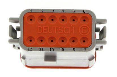
Expansion port connector DT06-12SA (ECU side). Mating connector (car side): DT04-12PA.
Table 3.0 — Expansion Port Pinout
| Pin | Function |
|---|---|
| 1 | Analog Sensor 0V Reference |
| 2 | 5.0V Aux Supply |
| 3 | AN 8 (e.g. Fuel Temp or Inlet Temp) |
| 4 | AN 9 (e.g. Fuel Temp or Inlet Temp) |
| 5 | AN 10 (e.g. Fuel Pressure) |
| 6 | DI 6 (e.g. Ethanol Content Sensor) |
| 7 | 14V Out Protected (ELC1 Power Supply) |
| 8 | Ground (ELC1 Ground) |
| 9 | Auxiliary Output 5 (e.g. Boost Control solenoid) |
| 10 | NC |
| 11 | CAN 1 Hi |
| 12 | CAN 1 Lo |
To minimise signal contamination and maximise noise immunity, twist the CAN High and CAN Low wire pair at a minimum of one twist per 40mm of cable.
4.0 ECU Channel Assignment
Injection
| ECU Channel | Function |
|---|---|
| Injection 1-4 | Port Fuel Injector Cyl 1-4 |
| Injection 5 | Rear Lambda Heater |
| Injection 6 | Purge |
| Injection 7 | DBW Power Supply Relay |
| Injection 8 | Direct Injection Power Supply Relay |
| Injection 9-12 | DI Fuel Injector Cyl 1-4 |
Ignition
| ECU Channel | Function |
|---|---|
| Ignition 1-4 | Ignition Cylinder 1-4 |
| Ignition 5 | Alternator Control |
| Ignition 6 | Engine Fan Relay |
| Ignition 7 | AC Clutch Relay |
| Ignition 8 | Starter Relay (Push Start) / Start Inhibit (Key Start) |
| Ignition 9-10 | Not Used |
| Ignition 11 | DI Fuel Pump Control |
| Ignition 12 | Not Used |
Analog Inputs
| ECU Channel | Function |
|---|---|
| Analog Voltage 1 | MAP |
| Analog Voltage 2 | DBW 1 Servo Position Main |
| Analog Voltage 3 | DBW 1 Servo Position Sub |
| Analog Voltage 4 | MAF |
| Analog Voltage 5 | Rear O2 Sensor |
| Analog Voltage 6 | IO Expansion Loom (e.g. Fuel Pressure) |
| Analog Voltage 7 (Pull-up) | Engine Temperature |
| Analog Voltage 8-10 (Pull-up) | IO Expansion Loom (IAT / F.Temp / F.Pressure) |
| Analog Voltage 11 (Pull-up) | Intake Temperature MAF |
| Analog Voltage 12 (Pull-up) | Engine Oil Temperature |
| Analog Voltage 13 | Pedal Position Sensor (PPS) Main |
| Analog Voltage 14 | Pedal Position Sensor (PPS) Sub |
Analog Voltage Channels 7-12 have switchable pull-ups suitable for temperature measurement.
Digital Inputs
| ECU Channel | Function |
|---|---|
| Digital Input 1 | Cam Position - Inlet RH |
| Digital Input 2 | Cam Position - Exhaust LH |
| Digital Input 3 | Cam Position - Exhaust RH |
| Digital Input 4 | Neutral Position Switch |
| Digital Input 5 | Direct Injection 1 Feedback |
| Digital Input 6 | IO Expansion Loom (e.g. Ethanol Sensor) |
| Digital Input 7 | Direct Injection 2 Feedback |
| Digital Input 8 | DI Fuel Pump Feedback |
| Digital Input 9 | Clutch Switch |
| Digital Input 10 | Start Signal from Starter Relay (Button Start) / NC (Key Start) |
| Digital Input 11 | AC Pressure (some models only) |
| Digital Input 12 | Start/Stop Switch (Button Start) / Start Signal from Starter Relay (Key Start) |
| Digital Input 13 | Brake Switch |
| Digital Input 14 | Cruise Control Switch |
Auxiliary Outputs
| ECU Channel | Function |
|---|---|
| Auxiliary 1 | VVT Solenoid Inlet RH |
| Auxiliary 2 | VVT Solenoid Inlet LH |
| Auxiliary 3 | VVT Solenoid Exhaust RH |
| Auxiliary 4 | VVT Solenoid Exhaust LH |
| Auxiliary 5 | IO Expansion Loom (e.g. Boost Control Solenoid) |
| Auxiliary 6 | Engine Speed Output |
| Auxiliary 7 | Fuel Pump Speed Control |
| Auxiliary 8 | AC Fan Relay |
| Auxiliary 9 | DBW + |
| Auxiliary 10 | DBW - |
| Auxiliary 11 | Start Inhibit (Button Start) / NC (Key Start) |
| Auxiliary 12 | Not Used |
| Auxiliary 13 | Canister Pump Module Relay (PPMP) |
| Auxiliary 14 | Canister Pump Module Relay (VPMP) |
| Auxiliary 15 | Canister Pump Module Relay (MPMP) |
| Auxiliary 16 | Not Used |
NoteNOTE Auxiliary Channels 13-15 have drivers suitable ONLY for relay control with switching currents that must be less than 0.5A.
Crank / Cam
| ECU Channel | Function |
|---|---|
| Crank Index | Crank Sensor |
| Sync Sensor | Cam Position - Inlet Bank 1 (LH) |
5.0 Plug-in Specific Information
5.2 Fuel Model
The ECU can use many combinations of methods to generate the fuel mass output. The base calibration is supplied using simple but common Speed Density (MAP). Commonly modified camshafts, aftermarket air bypass valves, larger turbochargers and modified intake piping tend to create unstable Mass Flow Sensor readings, so MAP-based fuel models tend to make the process much simpler. (Press F1 with the Fuel Model setting selected for more detailed help.)
When MAF is selected, the Secondary Load table can be used to scale the MAF if required. This table will need to be switched ON via Fuel Menu → Fuel Table Control → Secondary Load Table (set to a value of 12). There is also a runtime in the F3 Menu → Fuel Tab showing the current Fuel Model the ECU is running in.
5.3 Inlet Air Temperature
A factory-fitted Inlet Temperature Sensor is available on Analog Input 11 and should already be configured in the base calibration shipped with the ECU.
5.4 Check Engine Light
The control of this light is done through the CAN bus. The base calibration file has the output already configured and selected to “CAN Bus OEM”.
5.5 AirCon Switch
The AirCon Switch status is read through the CAN bus. The base calibration file has the Input Source selected to “CAN Bus OEM”.
6.0 Diagnostic Trouble Codes (DTCs)
On initial installation it is advised to clear all the DTCs if errors are reported. Connect to Emtune and look at the DTC status in the bottom toolbar (red if errors are present). Open the DTC window via the DTC Status box or File → Open DTC, select “Clear ALL DTCs”, and confirm all the Error Codes have been removed (status box goes green). If the error codes have not all been removed, select “Update DTC” then use the DTC window to locate the sensor that is on fault.
7.0 User CAN Bus 1
The ECU CAN Bus 1 is available for Input/Output expansion, allowing a wide range of Emtron CAN devices to be connected: ELC1/2 (Lambda to CAN), ETC4/ETC8M (Thermocouple to CAN), EIC10/EIC16M (Input to CAN).
7.1 Emtron Lambda to CAN
The ELC uses Bosch proven integrated circuit technology to precisely control an LSU4.9 Lambda sensor. The Lambda value is transmitted over the CAN Bus and can be used by the ECU for tuning and closed loop control. The ELC Power, Ground and CAN wires can be directly connected into the IO Expansion Loom:
Table 7.0 — ELC1 to IO Expansion Port wiring
| Name | ELC 4-Way DTM | ECU IO Expansion 12-Way DTM |
|---|---|---|
| Ground | Pin 1 | Pin 8 |
| CAN Lo | Pin 2 | Pin 12 |
| CAN Hi | Pin 3 | Pin 11 |
| Power | Pin 4 | Pin 7 |
8.0 OEM CAN Bus 2
The ECU communicates on CAN Bus 2, which is reserved for the GT86/BRZ/FR-S. The ECU maintains full compatibility with all other CAN devices within the vehicle, transmitting a wide range of raw and calibrated data over the Bus while also receiving data.
9.0 Emtron Torque Management
The ECU performs extremely accurate torque calculations provided the engine model configuration is accurate. This section allows the user to calibrate any errors in the torque model whilst also influencing the engine torque delivery characteristics.
- 9.1 Torque Reduction Ign Retard Clamp — Limits the maximum torque reduction the ECU can perform based on ignition timing retard.
- 9.2 Torque Nitrous Gain — In applications where Nitrous is used to increase torque, the ECU calculates this torque increase; the gain can be used to trim the output if required.
- 9.3 BSFC — Brake Specific Fuel Consumption torque calculation is not used by the ECU but can be useful, when calibrated correctly, to cross-check the ECU calculated torque levels.
- 9.4 Engine Torque Correction Table — Allows the user to adjust the gain on the calculated Engine Torque based on any parameter in the axis setup form (used to correct calibration errors).
- 9.5 Torque Demand Correction Table — The GT86/BRZ/FR-S requests accurate information on driver-demanded torque so decisions can be made across vehicle systems. If correlation issues exist between reported torque and Torque Demanded, the vehicle will not function as intended and can lead to drivetrain operation issues. This table allows gain control of this channel (should not normally require modification).
- 9.6 Frictional Loss Table — The combustion torque (“Torque Ideal”) is calculated by the ECU; the moving parts create drag and limit available torque. This table allows entry of the frictional loss in Nm.
- 9.7 Frictional Loss Offset 1 Table — One of two tables that allow offsetting of the frictional loss (commonly spanned against Engine Oil Temperature).
- 9.8 Torque Reduction Ignition Retard Gain Table — Calibrates the torque reduction % per degree. When a torque request is applied the ECU calculates how much retard is required to achieve it.
- 9.9 Torque Reduction Gain Table — Calibrates the torque reduction % per %cut. When a torque request is applied the ECU calculates how much cut is required to achieve it.
10.0 Ordering Information
| Product | Part Number |
|---|---|
| Emtron GT86/BRZ/FR-S Plugin | 1609-72086 |
Appendix A – ECU Pinout
Connector A
| Pin | Function | Channel Assignment |
|---|---|---|
| A1 | Throttle Servo Motor - | AUX1012 Supply (option 2) |
| A2 | Throttle Servo Motor + | AUX9 |
| A3 | Power Ground | GND |
| A4 | Power Ground | GND |
| A5 | Cam Solenoid Exhaust RH | Aux 4 |
| A6 | O2 NarrowBand Heater | GROUND |
| A7 | Cam Solenoid Exhaust LH | Aux 3 |
| A8 | Ignition 4 | Ign 4 |
| A10 | Ignition 2 | Ign 2 |
| A11 | Purge | Inj 6 |
| A12 | Injector 1 (Port) | Inj 1 |
| A13 | Injector 4 (Port) | Inj 2 |
| A14 | Injector 1 (Direct) | Inj 1 Direct |
| A16 | Cam Solenoid Inlet RH | Aux 2 |
| A17 | Cam Solenoid Inlet LH | Aux 1 |
| A18 | TPS (Main) | An 2 |
| A19 | 5V Engine (TP and VSV) | Eng 5V |
| A20 | Oil Temperature | An 10 |
| A21 | Ignition 1 | Ign 1 |
| A22 | Injector 2 (Port) | Inj 2 |
| A23 | Injector 4 (Direct) | Inj 4 Direct |
| A24 | Injector 3 (Direct) | Inj 3 Direct |
| A25 | Injector 2 (Direct) | Inj 2 Direct |
| A28 | TPS (Sub) | An 3 |
| A29 | Sensor Ground (Knk, MAF, Oil Temp, Eng Temp) | Sensor 0V Ref |
| A30 | ECT | An 7 |
| A31 | Ignition 3 | Ign 3 |
| A32 | Injector 3 (Port) | Inj 3 |
Connector B
| Pin | Function | Channel Assignment |
|---|---|---|
| B1 | Canister Pump Module (VPMP) | |
| B5 | Direct Injector Power Supply Relay | Inj 8 |
| B7 | DBW (ETCS) Power | Inj 7 |
| B8 | Canister Pump Module (MPMP) | |
| B10 | Fuel Pump Feedback | DI 5 |
| B11 | Cooling Fan Relay 3 | Ign 5 |
| B12 | Cooling Fan Relay 1 2 | Ign 6 |
| B13 | EFI Relay (Gnd) | |
| B15 | Tacho | Aux 6 |
| B17 | DBW Relay (Gnd) | Inj 7 |
| B18 | Alternator Control | Aux 8 |
| B19 | FPC | Aux 7 |
| B20 | Canister Pump Module | GROUND |
| B21 | 5V Eng (FPS Main) | 5V Eng |
| B22 | 5V Eng (FPS Sub) | 5V Eng |
| B23 | FPS Main Signal | An 13 |
| B26 | Starter Relay | Ign 8 |
| B29 | Sensor Ground (PP) | Sensor 0V Ref |
| B30 | Sensor Ground (PP) | Sensor 0V Ref |
| B31 | FPS Sub Signal | An 14 |
| B34 | Start Cut Relay | Aux 11 |
| B35 | AC Clutch | Ign 7 |
Connector C
| Pin | Function | Channel Assignment |
|---|---|---|
| C1 | Power Ground | GROUND |
| C2 | Power Ground | |
| C3 | Power Ground | |
| C5 | O2 Wideband Heater | |
| C6 | 14V ECU Power | |
| C9 | Fuel Pressure Signal | An 6 |
| C11 | DF1 | DI 5 |
| C13 | Fuel Pump Feedback | DI 8 |
| C14 | Exhaust Cam Position (LH) | DI 2 |
| C15 | Intake Cam Position (RH) | DI 1 |
| C16 | Crank Signal + | |
| C17 | Knock Signal (RH) | |
| C18 | O2 Wideband Sensor Signal 1 - | |
| C19 | O2 Wideband Sensor Signal 1 + | |
| C20 | Manifold Pressure Sensor | An 1 |
| C21 | O2 NarrowBand Sensor Signal 2 | |
| C25 | Exhaust Cam Position (RH) | DI 3 |
| C26 | Inlet Cam Position (LH) | Sync Index |
| C27 | Crank Signal - | |
| C28 | Knock Signal LH + | |
| C29 | Shield (Knock) | |
| C30 | Shield (O2) | |
| C31 | DF2 | DI 7 |
| C32 | Fuel Pump Driver | Aux 12 |
| C34 | 5V for CAM Sensors | 5V Eng |
| C35 | Shield (Crank) |
Connector D
| Pin | Function | Channel Assignment |
|---|---|---|
| D1 | 14V ECU Power | |
| D2 | Battery | |
| D3 | Brake Switch (NO) | |
| D4 | Signal Ground / Shielding | |
| D7 | Brake Switch (NC) | DI 13 |
| D8 | AC Pressure Sensor | DI 11 |
| D12 | Intake Temp (MAF) | AN 11 |
| D14 | Starter Signal from Start Relay | DI 10 |
| D15 | Clutch Switch | DI 9 |
| D16 | Neutral Switch | DI 4 |
| D17 | Start Request | DI 12 |
| D18 | CAN Lo | CAN Lo |
| D19 | CAN Hi | CAN Hi |
| D20 | GROUND | |
| D22 | MAF Signal | AN 4 |
| D24 | Battery Current Sensor | GROUND |
| D27 | Ignition Switch | |
| D28 | Shield (MAF) | |
| D29 | Ground (MAF) | |
| D30 | Cruise Switch (Main) | DI 14 |