Nissan Patrol Y61
Nissan Patrol Y61 Application Build
1.0 Introduction
The Patrol Y61 Application Build is available for all Emtron ECUs. This build allows unique application-specific firmware to be installed into the ECU. The Y61 build includes:
- Full CAN Bus OEM integration for both Automatic and Manual Transmissions
- Y61 Gearshift control for automatic transmissions — controls and monitors the Engine Torque during the gearshift
- Emtron Nissan Y61 Base Calibration File
- Cruise Control (requires a DBW and Pedal Position sensor be fitted)
This build version requires Firmware Version 2.17.0 or later. Emtron will supply a recommended pinout configuration that matches the supplied calibration file.
2.0 Build Setup
The Y61 Build needs to first be purchased before it can be installed into the ECU. Each build purchase is locked to an ECU serial number, then available for installation from the Emtron online server.
2.1 Installation procedure
- Internet access is required for the build installation, allowing Emtune to access the Emtron online server.
- Connect Emtune to the ECU.
- Select the File → Build Management menu. A window will open and display all build options.
- Select the Y61 option which should be listed as INSTALL. Press OK.
- The installation process takes 5-10 seconds. A message box will confirm a successful installation.
- To verify the installation and view the status of all available builds, open the Runtime menu (F3) and select the “ECU Internal” tab.
2.2 Uninstall procedure
With internet access and Emtune connected, select File → Build Management, select the Y61 option (listed as UNINSTALL) and press OK. The uninstall process takes 5-10 seconds.
3.0 CAN Bus
The Y61 Base Calibration file is configured for OEM CAN Bus integration using CAN 2. It is highly recommended that no other CAN device(s) be connected to this Bus. Any additional CAN Bus IO expanding devices should be connected to CAN 1.
3.1 OEM CAN Bus – CAN 2
The ECU provides full integration with the OEM CAN bus, both receiving and transmitting data. Critical data like Engine Torque must be calibrated correctly as this is transmitted and used by other systems throughout the vehicle.
Once the build has been installed a “Patrol Y61” tab will be available in the Runtime menu (F3), providing application-specific data received over the CAN bus:
| ECU Input Channel Name | Description |
|---|---|
| Vehicle Speed | The average speed of the rear wheels |
| Input Shaft Speed | Input shaft speed of the transmission |
| Gear | Current gear reported by the transmission ECU |
| Gear Request | Current gear requested, reported by the transmission ECU |
| Upshift Request Switch | Upshift request reported by the transmission ECU |
| Downshift Request Switch | Downshift request reported by the transmission ECU |
| Cruise Control Switch | Cruise Control Off/On Switch |
ImportantIMPORTANT When wiring into the OEM CAN Bus a 120 Ohm CAN terminating resistor MUST be installed.
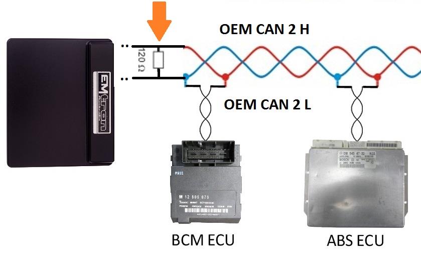
Figure 3.0 — OEM CAN Bus 120 Ohm CAN termination.
3.2 User CAN Bus – CAN 1
The following devices can be connected to the ECU CAN 1 inputs: ELC1/2 (Emtron Lambda to CAN), ETC4/ETC8M (Emtron Thermocouple to CAN), EIC10/EIC16M (Emtron Input to CAN). Standard CAN bus precautions apply — use twisted pair (min one twist per 40mm), minimise connectors, terminate with a 120 ohm 0.25W resistor at each END of the bus, and keep stub lengths under 0.3m (ISO 11898). All Emtron CAN devices have no on-board terminating resistor, allowing them to be wired at any position on the Bus.
4.0 Application Specific Functions
4.1 Gearshift Control Function Setup
The Nissan Patrol Y61 Application Build includes a special gearshift control feature specific to the vehicle (already enabled in the supplied build). To enable, go to Config → Functions → Function Output Setup → Motorsport functions → Gear Shift Control and select “Nissan Y61 – CAN BUS”.
4.2 Gearshift Control Function Tuning
Once enabled, the tuning view menu item “Gearshift Control Y61” is available. The ECU has no control over the actual shift points — this is handled by the OEM transmission control system. The ECU can only control torque during a gearshift request event, most commonly via a cut event or throttle reduction.
4.3 Gearshift Y61 Setup Menu
All gearshift torque reduction settings are calibrated here.
- Next Gear Stable Gear Position Source — The input source the ECU uses to consider the gearshift complete (cuts, throttle reductions and retards will be removed). Typical Setting: Gear Position – Input/Output shaft.
4.4 Up Shift Control Menu
4.41 Upshift Setup Menu
- Upshift Torque Reduction Cut Type — Cut type used for upshift torque reduction. Typical: Fuel + Ign Cut.
- Upshift Ign Retard Mode — How the ignition retard is calculated. Typical: Percentage.
- Upshift Torque Reduction Min Time — Minimum time a torque reduction can occur regardless of table configuration. Typical: 20ms.
- Upshift Throttle Override — A throttle override may be used to reduce torque, timed by either the function or a user duration. Typical: OFF.
- Upshift Rev-matching Limit — The ECU can calculate the engine speed required to match the transmission ratios using the output shaft speed and gear ratios. Typical: ON Outputshaft Speed Calculated.
- Upshift Rev-match Cut Type — The rev-matching function limits engine RPM to match the requested upshift gear, using output shaft RPM and transmission ratios. Typical: Ign Cut.
- NOTE 1: Output Shaft must be configured (Wheel Diameter and Final Drive ratios set correctly).
- NOTE 2: The Gear Ratio Table MUST be completed (Vehicle Functions → Vehicle Dynamics menu).
- NOTE 3: Rev-match RPM limiting should start AFTER the initial Torque Reduction Cut/Retard, otherwise the Rev-Match RPM limit (lower than current engine speed) takes %cut priority and prevents the initial reduction from working.
- Upshift Rev-match Control Range (-/+) — The engine speed range the ECU calculates the cut % over. Typical: 150rpm.
- Example: Rev-match RPM Target = 4700, Min Cut = 0%, Max Cut = 95%. Range +500 RPM → 4700 RPM = 0% Cut, 5300 RPM = 95% Cut. Range -500 RPM → 4700 RPM = 95% Cut, 4200 RPM = 0% Cut.
- Upshift Rev-match %Cut Clamp — Percentage cut applied to the engine at the end of the control range.
- Upshift Next Gear Timeout — The next gear must be reached within this time for the upshift to be valid; otherwise the ECU re-tries the gear shift per the “Upshift Re-retry Count” setting.
4.42–4.46 Torque Reduction Tables
- Torque Reduction Ign %Cut Level — Sets the ignition %cut level. The default table only provides a cut when torque levels are high, preventing cuts during normal driving.
- Torque Reduction Fuel %Cut Level — As above, for fuel %cut.
- Upshift Torque Reduction Retard — Controls the retard component of the torque reduction.
- Upshift Re-Match Enable Table — Controls when the torque reduction reverts from cut-table control to the rev-matching strategy.
- Upshift Re-Match RPM Target Correction — Ensures positive torque when on the throttle. Default is a global value of 20%.
4.47–4.411 Additional Upshift Settings
- Upshift DBW 1 Position — Not Used by Default.
- Upshift Throttle 1 Duration — Not Used by Default.
- Upshift Next Gear Torque Recovery Delay — Typical: 0ms.
- Upshift Next Gear %Cut Level Recovery Delay — Typical: 0ms.
- Upshift Next Gear Ignition Recovery Time — Typical: 0ms.
4.5 Down Shift Control Menu
There is no implementation of this feature at the time of writing.
5.0 Cruise Control
5.1 OEM Cruise Control
The Nissan Patrol Y61 comes fitted with OEM cruise control. A cable is actuated by the cruise control module and overrides the electronic throttle. The ECU has no control over this function and it will operate as normal if the factory throttle body is fitted.
5.2 Emtron Cruise Control
If the factory throttle body is replaced with an aftermarket unit there is no way for the OEM cruise control to operate. Modern DBW throttle bodies will require a custom fitment of a pedal position sensor. Emtron has a special channel for the factory cruise control buttons which is decoded so they may be used with the Emtron Cruise Control feature.
5.21 Emtron Cruise Control Application Build — The Y61 build already has the Emtron Cruise Control function enabled if using firmware V2.17.0 or later. See the Cruise Control build for detailed tuning information.
5.22 Nissan Patrol Y61 Cruise Command Switch — The Factory Cruise Command Switch only requires one wire to be spliced and pinned into the ECU. Any spare Analog Volt or Digital Input may be allocated for this switch. Once pinned in, configure the channel by selecting only the ECU pin (e.g. ANV 10) — no further input configuration is required. To test, press F3 to open the ECU Runtimes form and confirm each button changes state when pressed.
6.0 ECU Channel Assignment
Injection
| ECU Channel | Function |
|---|---|
| Injection 1-6 | Fuel Injector Cyl 1-6 |
| Injection 7 | AC Clutch Relay |
| Injection 8 | Tachometer |
| Injection 9-12 | Not Used |
Ignition
| ECU Channel | Function |
|---|---|
| Ignition 1-6 | Ignition Cyl 1-6 |
| Ignition 7-12 | Not Used |
Analog Inputs
| ECU Channel | Function |
|---|---|
| Analog Voltage 1 | MAP |
| Analog Voltage 2 | DBW Servo Position Main |
| Analog Voltage 3 | DBW Servo Position Sub |
| Analog Voltage 4 | Pedal Position (Main) |
| Analog Voltage 5 | Pedal Position (Sub) |
| Analog Voltage 6 | Not Used |
| Analog Voltage 7 (Pull-up) | Engine Temperature |
| Analog Voltage 8 (Pull-up) | Inlet Air Temperature |
| Analog Voltage 9 (Pull-up) | Mass Air Flow Sensor |
| Analog Voltage 10 (Pull-up) | *Cruise Command Switch (Y61) |
| Analog Voltage 11-12 (Pull-up) | Not Used |
| Analog Voltage 13-14 | Not Used |
Analog Voltage Channels 7-12 have switchable pull-ups suitable for temperature measurement. *Cruise Command Switch used when replacing the throttle body with an aftermarket unit.
Digital Inputs
| ECU Channel | Function |
|---|---|
| Digital Input 4 | Power Steer Switch |
| Digital Input 6 | Snow Switch |
| Others | Not Used |
Auxiliary Outputs
| ECU Channel | Function |
|---|---|
| Auxiliary 1 | CAM Switch Solenoid |
| Auxiliary 2 | User Output 1 – Manifold Flap |
| Auxiliary 3 | Engine Fan Relay |
| Auxiliary 4 | Fuel Pump Relay |
| Auxiliary 9 | DBW + |
| Auxiliary 10 | DBW - |
| Others | Not Used |
Crank / Cam
| ECU Channel | Function |
|---|---|
| Crank Index | Crank Sensor |
| Sync Sensor | Cam Position Sensor |
CAN
| ECU Channel | Function |
|---|---|
| CAN 1 Lo/Hi | User CAN Bus Lo/Hi |
| CAN 2 Lo/Hi | OEM CAN Bus Lo/Hi |
OEM CAN Inputs
AC Switch, Brake Switch 1, Cruise Enable, Drive Speed, Input Shaft Speed, Gear Upshift Switch, Gear Downshift Switch.
7.0 Y61 ECU Pinout
| OEM Pin | Function | ECU Channel |
|---|---|---|
| 5 | Injector Cylinder 1 | Injector 1 |
| 6 | Injector Cylinder 2 | Injector 2 |
| 7 | Injector Cylinder 3 | Injector 3 |
| 13 | Injector Cylinder 4 | Injector 4 |
| 14 | Injector Cylinder 5 | Injector 5 |
| 15 | Injector Cylinder 6 | Injector 6 |
| 18 | Ignition Cylinder 1 | Ignition 1 |
| 19 | Ignition Cylinder 2 | Ignition 2 |
| 20 | Ignition Cylinder 3 | Ignition 3 |
| 21 | Ignition Cylinder 4 | Ignition 4 |
| 24 | AC Clutch | Injector 7 |
| 27 | Inlet Manifold Flap | Aux 2 |
| 29 | Ignition Cylinder 5 | Ignition 5 |
| 30 | Ignition Cylinder 6 | Ignition 6 |
| 38 | Tachometer | Injector 8 |
| 40 | Fuel Pump | Aux 4 |
| 42 | EFI Relay Control | EFI Relay |
| 48 | Idle Stepper | Aux 5 |
| 49 | Idle Stepper | Aux 7 |
| 50 | Idle Stepper | Aux 6 |
| 51 | Idle Stepper | Aux 8 |
| 52 | Speed Sensor | DI 1 |
| 53 | Ignition Switch | IGN Switch |
| 55 | Cooling Fan | Aux 3 |
| 60 | Snow Switch | DI 6 |
| 63 | Engine Speed Sensor | Crank Index +ve |
| 79 | Steering Pressure Switch | DI 4 |
| 84 | Engine Sync Sensor | Sync Index +ve |
| 86 | AC Request | DI 5 |
| 87 | Pedal Position Sensor Main | AN 4 |
| 89 | Sensor Ground | Sensor 0V Ref |
| 94 | +5V Supply | 5.0V VRef1 |
| 98 | Throttle Servo Sub | AN 3 |
| 100 | Sensor Ground | Sensor 0V Ref |
| 108 | Throttle Servo Main | AN 2 |
| 109 | Sensor Ground | Sensor 0V Ref |
| 117 | Pedal Position Sensor Sub | AN 5 |
| 121 | Coolant Temp Sensor | AN 7 |
| 125 | Knock Sensor Rear +ve | Knock Sensor 2 +ve |
| 126 | Knock Sensor Front +ve | Knock Sensor 1 +ve |
| 151 | Throttle Motor +ve *(Auto Only) | Aux 9 |
| 152 | Inlet Cam Actuator | Aux 1 |
| 153 | Ground | Ground |
| 154 | Throttle Motor -ve *(Auto Only) | Aux 10 |
| 156 | Ground | Ground |
| 158 | Ground | Ground |
| 159 | Ground | Ground |
| 163 | ECU Supply | Aux 9-10 Supply / ECU Supply |
| 165 | Ground | Ground |
| 166 | ECU Supply | Aux 9-10 Supply / ECU Supply |
| 168 | Ground | Ground |
| 171 | OEM CAN LO | CAN 1 LO |
| 174 | OEM CAN HI | CAN 1 HI |