Nissan GTR R35
Documentation for the Emtron R35 GT-R Plug-in ECU — installation, VDC integration, TCM setup, and tuning.
Start with Nissan GTR R35 Build for the plug-in installation reference.
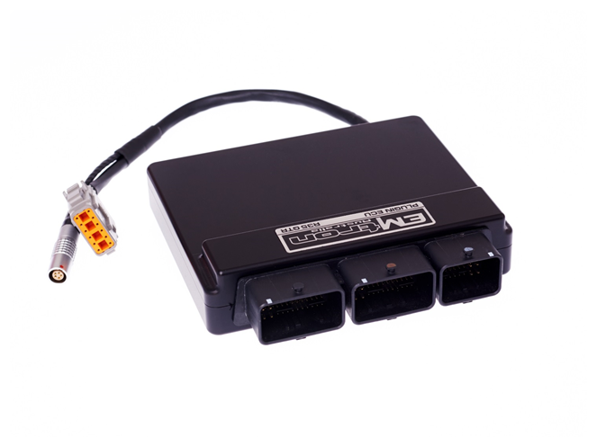
Documentation for the Emtron R35 GT-R Plug-in ECU — installation, VDC integration, TCM setup, and tuning.
Start with Nissan GTR R35 Build for the plug-in installation reference.
Nissan GTR R35 dedicated menu shown with GTR R35 build enabled
The Nissan R35 GT-R’s turbo control system and monitoring is different than many turbocharged cars.
Commonly turbocharged engines have a common plenum that feeds all the engines cylinders.
Each cylinder draws air from a common plenum.
On the Nissan R35 GT-R one bank feeds one set of three cylinders(1-3) and the other turbo feeds the other three cylinders (4-6) via separated plenum’s. There is also a cross over balance pipe between the plenum’s.
To correctly calculate the fueling requirements for each bank the ECU uses MAF Meter 1 (Bank 1) to control the fueling on Cylinders 1-3 and MAF Meter 2 (Bank 2) to control the fueling on Cylinders 4-6. There are also boost pressure sensors on each bank along with a single manifold pressure sensor on one bank. These pressure sensors allow for various calculations to be made by the ECU, offering a number methods to use for fuel calculations.
The Emtron R35 GT-R Plug-in ECU is a replacement engine management system designed to be installed and integrate seamlessly with the vehicle, whilst also allowing extreme flexibility and control from the KV12 based ECU platform.
The Nissan GTR R35 tab allows access to dedicated R35 features:
▪ Nissan Vehicle Dynamic Control (VDC) – This system employs an extremely complex system of vehicle sensors including wheel speed, steering angle, g-force and yaw which are used to generate various torque requests which the ECU must abide by accurately. This will not only achieve maximum vehicle performance, it is also a safety feature.
▪ Nissan Transmission Control Module Integration (TCM) - The ECU must accurately calculate and perform torque requests assigned by the TCM for the drive-train to function correctly and smoothly for all driving conditions. Limitations on the transmission torque capacity must also be considered and hence another reason why the torque supplied by the engine must be accurately metered.
▪ Launch Control – The TCM provides the ECU torque requests during a launch OFF mode and is able to place the ECU into launch mode where the Torque Limit is not requested, allowing the ECU to increase the launch limit through a raised engine speed limit and an ECU determined torque limit.
▪ Downshift Rev Matching – The ECU must accurately calculate and increase torque to smoothly match the engine RPM in the next gear on downshift, by increasing the throttle mass flow (TMF) during the downshift event until the TCM is satisfied with the engine speed and torque levels.
NoteNOTE This page covers the plug-in install reference. For the detailed dedicated R35 tuning menus see Nissan GTR R35 VDC, Nissan GTR R35 TCM and TCM Torque Limit Engine Cut Setup.
Communications: CAN 2.0B Node 1 — User CAN Bus for I/O expansion (Lambda, EGT); CAN 2.0B Node 2 — 500k Baud Full CAN Bus OEM Integration; High Speed Ethernet 100Mbps.
Operating Temperature: -30 to 125°C (-22 to 257°F). Physical: 160 × 162 × 38 mm, 890g.
When purchasing a Nissan R35 plug-in the following items are included:
The ECU’s Input capabilities can be expanded using the expansion connection, which is a male DTM 12 Way. These additional inputs can be connected to any sensor, but the recommended sensors are indicated in brackets.
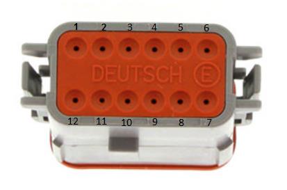
DTM 12 Way expansion loom connector (ECU side).
| Pin | Function |
|---|---|
| 1 | Analog Sensor 0V Reference |
| 2 | 5V Aux Supply |
| 3 | AN 10 (e.g. Fuel Temp or Inlet Temp) |
| 4 | Not Used |
| 5 | AN 6 (e.g. Fuel Pressure) |
| 6 | DI 6 (e.g. Ethanol Content Sensor) |
| 7 | 14V Out Protected (ELC2 Power Supply) |
| 8 | Ground (ELC2 Ground) |
| 9 | 14V Out Protected (ELC2 Power Supply) |
| 10 | Ground (ELC2 Ground) |
| 11 | CAN 1 Hi |
| 12 | CAN 1 Lo |
| ECU Channel | Function |
|---|---|
| Injection 1-12 | Fuel Injector Cylinder 1-12 |
| ECU Channel | Function |
|---|---|
| Ignition 1-6 | Ignition Cylinder 1-6 |
| Ignition 7 | DBW Relay |
| Ignition 8 | Spare |
| Ignition 9-12 | Not Used |
| ECU Channel | Function |
|---|---|
| Analog Voltage 1 | MAP |
| Analog Voltage 2 | DBW Servo Position Main Bank 1 |
| Analog Voltage 3 | DBW Servo Position Sub Bank 1 |
| Analog Voltage 4 | DBW Servo Position Main Bank 2 |
| Analog Voltage 5 | DBW Servo Position Sub Bank 2 |
| Analog Voltage 6 | Fuel Pressure |
| Analog Voltage 7 (Pull-up) | Engine Temperature |
| Analog Voltage 8 (Pull-up) | Airbox Temperature |
| Analog Voltage 9 (Pull-up) | Engine Oil Temperature |
| Analog Voltage 10 (Pull-up) | IO Expansion loom (Emtron Fuel Temp/IAT) |
| Analog Voltage 11 (Pull-up) | Pedal Position Sensor (PPS) Main |
| Analog Voltage 12 (Pull-up) | Pedal Position Sensor (PPS) Sub |
| Analog Voltage 13 | MAF Bank 1 |
| Analog Voltage 14 | MAF Bank 2 |
| ECU Channel | Function |
|---|---|
| Digital Input 1 | Cam Position - Inlet RH |
| Digital Input 2 | Brake Switch |
| Digital Input 3 | Neutral Switch |
| Digital Input 4 | Fuel Level |
| Digital Input 5 | Steering Wheel Button |
| Digital Input 6 | IO Expansion Loom (Ethanol Sensor) |
| Digital Input 7 | FP Feedback Sec Pump |
| Digital Input 8 | FP Feedback Prim Pump |
| Digital Input 9 | Power Steering Pressure |
| Digital Input 10 | Evap System Pressure |
| Digital Input 11 | Secondary Air MAF Sensor |
| Digital Input 12 | Boost Pressure Bank 1 |
| Digital Input 13 | Boost Pressure Bank 2 |
| Digital Input 14 | AC System Pressure |
| ECU Channel | Function |
|---|---|
| Auxiliary 1 | VVT Solenoid Bank 1 |
| Auxiliary 2 | VVT Solenoid Bank 2 |
| Auxiliary 3 | Purge |
| Auxiliary 4 | Wastegate Solenoid |
| Auxiliary 5 | Sub Fuel Pump |
| Auxiliary 6 | Purge Vent |
| Auxiliary 7 | Fuel Pump Speed Control |
| Auxiliary 8 | Tacho |
| Auxiliary 9 | DBW + Bank 1 |
| Auxiliary 10 | DBW – Bank 1 |
| Auxiliary 11 | DBW + Bank 2 |
| Auxiliary 12 | DBW – Bank 2 |
| Auxiliary 13 | Air Pump Relay |
| Auxiliary 14 | Air Cut Solenoid Relay Control (Bank 1 & 2) |
| Auxiliary 15 | Narrow Band Sensor Heater |
| Auxiliary 16 | Not Used |
| ECU Channel | Function |
|---|---|
| Crank Index | Crank Sensor |
| Sync Sensor | Cam Position - Inlet Bank 1 (LH) |
Injector channels 7-12 are available in the OEM header and can be used for additional outputs or for Sequential Staged Injection: Injector Ch 7 = A11, Ch 8 = A12, Ch 9 = A16, Ch 10 = A35, Ch 11 = A39, Ch 12 = A43.
The base calibration is supplied with a Blend method of MAP Modelled (MAP Sensor and MAP Estimate) and Mass Air Flow (MAF Sensor). A fully adjustable combination of Throttle Pressure Ratio and Air Mass balances the priority of the two inputs. Many other fuel modelling methods are possible, including removing the MAF Sensors completely — a common implementation when the OEM sensors don’t allow enough flow, or when engine modifications (cams, air bypass valves, larger turbos, modified intake piping) generate unstable Mass Flow readings. When MAF is selected, the Secondary Load table can be used to scale the MAF (switch ON via Fuel Menu → Fuel Table Control → Secondary Load Table, set to 12).
A factory-fitted Inlet Temperature Sensor is available on Analog Input 8 and should already be configured in the base calibration.
Both are handled through the CAN bus; the base calibration has the CE Light output and Air-Con Switch input source already configured and selected to “CAN Bus OEM”.
The ECU CAN Bus 1 is available for I/O expansion (ELC1/2, ETC4/ETC8M, EIC10/EIC16M). The ELC Power, Ground and CAN wires connect directly into the ECU IO Expansion Loom using the supplied 12 way DTM to ELC Adapter Loom (120 Ohm termination resistors pre-installed — completely plug and play). If other devices are added to the CAN bus, ensure no additional resistors are introduced.
| Name | ELC 4-Way DTM | ECU IO Expansion 12-Way DTM |
|---|---|---|
| Ground | Pin 1 | Pin 8 |
| CAN Lo | Pin 2 | Pin 12 |
| CAN Hi | Pin 3 | Pin 11 |
| Power | Pin 4 | Pin 7 |
The ECU communicates on CAN Bus 2, reserved for the R35 GT-R, maintaining full compatibility with all other CAN devices in the vehicle. Emtune has a dedicated R35 GT-R runtime tab; these runtimes are available throughout the ECU’s functions and viewable in the Emtune logger.
The ECU performs accurate torque calculations provided the engine model configuration is accurate. The Torque Management section allows the user to calibrate errors in the torque model whilst influencing torque delivery: Torque Reduction Ign Retard Clamp, Torque Nitrous Gain, BSFC, Engine Torque Correction Table, Torque Demand Correction Table, Frictional Loss Table (+ Offset 1 Table, commonly spanned against Engine Oil Temperature), Torque Reduction Ignition Retard Gain Table (% per degree) and Torque Reduction Gain Table (% per %cut).
Launch Control is enabled in the base calibration. The TCM controls how it is armed — the ECU arms based on enabling R Mode of the transmission. The feature allows the user to target a torque level; the base calibration leverages Engine Speed Limit 2 (RPM Limit 2 Table) to control engine speed during launch. The correct torque target achieves good acceleration and traction without requiring engine speed limiting once the vehicle is moving.
Torque information over the CAN bus can be modified (a ±500Nm offset table), changing gearshift behaviour and in-gear clutch pressure. If there is excessive slip, increase the reported Torque; if the gearshift feel is too sharp/aggressive, reduce it. This affects Engine Torque Demand and Engine Torque. Note: directly programming the TCM through a third-party flashing tool is advised over using the ECU to offset the torque reported.
| Product | Part Number |
|---|---|
| Emtron R35 Plugin | 1609-1835 |
| OEM Pin | Function | Channel Assignment |
|---|---|---|
| A1 | Throttle Control Motor Supply (paired with pin 49) | AUX 9-12 Supply (option 2) |
| A2 | Throttle Servo Bank 2 Motor + | AUX11 |
| A3 | AF Sensor 2 Heater (denso narrowband) | AUX15 |
| A4 | AF Sensor 1 Heater (denso narrowband) | AUX15 |
| A5 | Throttle Servo Bank 2 Motor - | AUX12 |
| A6 | Power Ground | GROUND |
| A7 | Evaporative Purge Canister Vent Control Valve | AUX6 |
| A8 | Evaporative Purge Canister Volume Control Solenoid | AUX3 |
| A9 | Ignition Cylinder 2 | Ignition Channel 2 |
| A10 | Ignition Cylinder 1 | Ignition Channel 1 |
| A11 | Secondary Injector 1 | Injector Channel 7 |
| A12 | Secondary Injector 2 | Injector Channel 8 |
| A13 | Ignition Cylinder 3 | Ignition Channel 3 |
| A15 | TPS Bank 2 Ground | Sensor Ground 1 |
| A16 | Secondary Injector 3 | Injector Channel 9 |
| A17 | Fuel Injector Cylinder 3 | INJ 3 |
| A19 | MAF Sensor Bank 2 Ground | Sensor Ground 1 |
| A20 | TPS Bank 1 Ground | Sensor Ground 1 |
| A21 | Fuel Injector Cylinder 2 | INJ 2 |
| A22 | MAF Sensor Bank 1 Ground | Sensor Ground 1 |
| A23 | SAMAF and TAM Ground | Sensor Ground 1 |
| A24 | Secondary Air Injection MAF Sensor (SAMAF) | DI 11 |
| A25 | Fuel Injector Cylinder 1 | INJ 1 |
| A26 | Engine Oil Temp / Engine Temp Ground | Sensor Ground 1 |
| A27 | Engine Oil Temperature | ANV9 |
| A28 | Throttle Servo Bank 2 Position Main | ANV4 |
| A29 | Fuel Pump Control Signal | AUX7 |
| A30 | Fuel Pump Control Diag Input | DI 8 |
| A31 | Mass Flow Sensor Bank 1 | ANV13 |
| A32 | Throttle Servo Bank 2 Position Tracking | AV5 |
| A33 | Ignition Cylinder 4 | Ignition Channel 4 |
| A34 | Ignition Cylinder 5 | Ignition Channel 5 |
| A35 | Secondary Injector 4 | Injector Channel 10 |
| A36 | Throttle Servo Bank 1 Position Tracking | ANV3 |
| A37 | Fuel Injector Cylinder 4 | INJ 4 |
| A38 | Ignition Cylinder 6 | Ignition Channel 6 |
| A39 | Secondary Injector 5 | Injector Channel 11 |
| A40 | Throttle Servo Bank 1 Position Main | ANV 1 |
| A41 | Fuel Injector Cylinder 5 | INJ 5 |
| A42 | Fuel Level Sensor | ANV 10 |
| A43 | Secondary Injector 6 | Injector Channel 12 |
| A44 | Airbox Temperature | ANV8 |
| A45 | Fuel Injector Cylinder 6 | INJ 6 |
| A46 | Coolant Temperature | ANV7 |
| A47 | Inlet Mass Flow Bank 2 | ANV14 |
| A48 | Inlet Manifold Pressure Bank 2 | ANV1 |
| OEM Pin | Function | Channel Assignment |
|---|---|---|
| B49 | Throttle Control Motor Supply (paired with pin 1) | Aux 9-12 Supply (option 1) |
| B50 | Throttle Servo Bank 1 Motor + | AUX 9 |
| B51 | Inlet Camshaft Bank 2 Solenoid | AUX 2 |
| B52 | Inlet Camshaft Bank 1 Solenoid | AUX 1 |
| B53 | Throttle Servo Bank 1 Motor - | AUX 10 |
| B54 | Power Ground | GROUND |
| B55 | O2HR1 - Wideband bank 1 Heater | Not Connected |
| B56 | O2HR2 - Wideband bank 2 Heater | Not Connected |
| B61 | Boost Control Solenoid | AUX 4 |
| B62 | Ground - Camshaft Position Bank 1 | Sync Sensor - |
| B63 | Camshaft Bank 1 Position Sensor (inlet) | Sync Sensor + |
| B64 | Crankshaft Position Sensor | Crank Index + |
| B66 | Ground - Camshaft Position Bank 2 | Sync Sensor - |
| B67 | Camshaft Bank 2 Position Sensor (Inlet) | DI 1 |
| B68 | Ground - Crankshaft Position Sensor | Crank Index - |
| B70 | Ground - WB Sensor 1 and 2 (joined in loom) | GROUND |
| B71 | Knock Sensor Ground for Bank 1 and 2 (joined) | ECU Ground |
| B72 | Knock Sensor Bank 1 | Knock 1 + |
| B73 | O2SR1 - Wideband bank 1 sensor | Not Connected |
| B74 | Ground (Power Steer Pres, MAP, Refrigerant Pres) | Sensor Ground 1 |
| B75 | Ground (Evap sensor, Boost sensor Bank 1 and 2) | Sensor Ground 1 |
| B76 | Knock Sensor Bank 2 | Knock 2 + |
| B77 | O2SR2 - Wideband bank 2 sensor | Not Connected |
| B78 | Evap Control System Pressure Sensor | DI 10 |
| B79 | Boost Pressure Bank 2 | DI12 |
| B80 | Boost Pressure Bank 1 | DI13 |
| B81 | Denso Sensor AF+ (Bank 1 Narrowband) | Not Connected |
| B82 | Denso Sensor AF- (Bank 1 Narrowband) | Sensor Ground 1 |
| B83 | Power Steering Pressure | DI 9 |
| B84 | 5V Supply - TPS Bank 2 | 5V Engine Supply |
| B85 | Denso Sensor AF+ (Bank 2) | Not Connected |
| B86 | Denso Sensor AF- (Bank 2) | Sensor Ground 1 |
| B87 | 5V Supply - Crankshaft | 5V Trigger Supply |
| B88 | 5V Supply - Camshaft Position Bank 1 | 5V Trigger Supply |
| B89 | Air Conditioner Refrigerant Pressure | DI 14 |
| B91 | 5V Supply - Camshaft Position Bank 2 | 5V Trigger Supply |
| B92 | 5V Supply - Evap sensor, Boost sensor Bank 1/2 | 5V Aux Supply |
| B93 | Sub Fuel Pump + (feedback) | DI 7 |
| B94 | Sub Fuel Pump - (feedback) | Not Connected |
| B95 | 5V Supply - Power Steer Pres, MAP, Refrig Pres | 5V Engine Supply |
| B96 | 5V Supply - TPS Bank 1 | 5V Engine Supply |
| OEM Pin | Function | Channel Assignment |
|---|---|---|
| C97 | 500k vehicle CAN bus to ABS | CAN 2 LO (500kbps) |
| C99 | 5V Supply - Pedal Position Sensor 2 | 5V Engine Supply |
| C100 | 5V Supply - Pedal Position Sensor 1 | 5V Engine Supply |
| C101 | 500k vehicle CAN bus to ABS | CAN 2 HI |
| C102 | Steering Wheel Button | DI 5 |
| C103 | Ground - Pedal Position Sensor 1 | Sensor Ground 1 |
| C104 | Pedal Position Main | ANV11 |
| C105 | ECM relay | EFI Relay |
| C106 | Ignition Switch | Ignition Switch |
| C107 | Ground - Pedal Position Sensor 2 | Sensor Ground 1 |
| C108 | Pedal Position Tracking | ANV12 |
| C109 | Air Cut Solenoids Relay Control (Banks 1 & 2 joined) | AUX14 |
| C110 | Brake Switch (Stop Lamp Switch) | DI 4 |
| C111 | Neutral Switch (from TCM) | DI 3 |
| C113 | Tacho out (To Power Steer control unit) | AUX 8 |
| C114 | K-Line | |
| C117 | Cruise Control Brake Switch | DI 2 |
| C118 | Keep Alive Memory power | Hot Supply |
| C120 | Air Pump Relay | AUX 13 |
| C121 | VBR - Power from ECM Relay (Sec Air Inj Pump, MAF) | ECU Supply |
| C122 | VBR - Power from ECM Relay | ECU Supply |
| C124 | Power Ground | GROUND |
| C126 | Sub Fuel Pump Relay | AUX 5 |
| C127 | DBW on/off relay (coil power from ECM Relay) | IGN 7 |
| C128 | Power Ground | GROUND |
The Nissan Vehicle Dynamic Control (VDC) uses various sensors to monitor driver inputs and vehicle motion.
The system takes control of braking and control of the engine output to achieve optimal performance, whilst keeping the vehicle on the steered path.
It is extremely important that the engine management system integrates seamlessly to achieve the correct functionality.
The Emtron R35 GT-R Plugin ECU is designed to replicate the OEM engine torque output by accepting and abiding by torque requests from the VDC system.
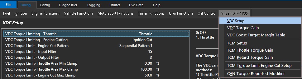
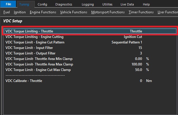
The VDC can request a Nm Torque Reduction/Limit using a combination of 2 methods:
Throttle Plate Area control (TMF)
Engine Cutting
These are separate requests sent over the CAN Bus from the VDC module to the ECU. The ECU then
uses a series of calculations to convert the Torque reduction request into either Throttle Plate position
or/and Engine Cut percentage.
The VDC primary Torque Limiting is done by using the Throttle Plate. The ECU uses Throttle Mass
Flow calculations to derive the required Throttle Area for a given Torque Target.
In some situations this may be insufficient to limit Engine Torque so a blend of Throttle Area
reduction and engine cutting maybe required.
Default: Throttle.
0: OFF
1: Throttle
The VDC can request a Nm Torque Reduction/Limit using a combination of 2 methods:
Throttle Plate Area control (TMF)
Engine Cutting
These are separate requests sent over the CAN Bus from the VDC module to the ECU. The ECU then
uses a series of calculations to convert the Torque reduction request into either Throttle Plate position
or/and Engine Cut percentage.
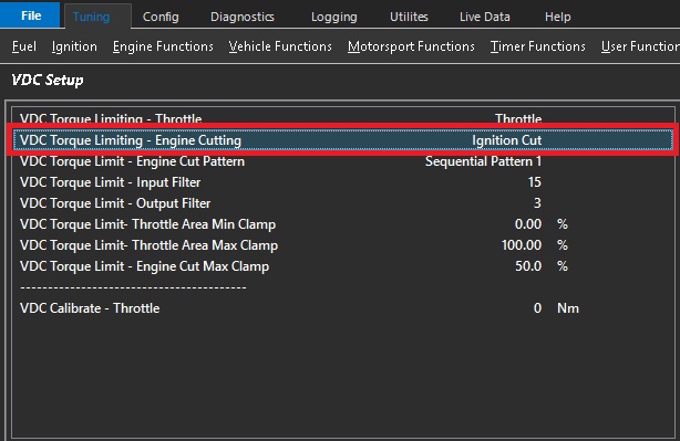
The VDC secondary Torque Limiting is done by Engine Cutting.
A VDC Torque Limit (Nm) using Engine Cutting gets converted by the ECU into a calibrated
Engine Cut percentage using the following parameters:
Engine Ideal Torque
Frictional Loss
Torque Reduction Cut Gain Table
CAUTION: When selected to OFF, the ECU will ignore the Torque Limit Cut requests from the VDC module.
Default: Ignition Cut.
0: OFF
1: Ignition Cut
2: Fuel Cut
3: Ignition + Fuel Cut
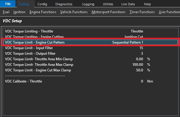
Used when VDC Torque Limiting is controlled with Engine Cutting.
Allows the cutting pattern to be selected.
All patterns will achieve the calculated torque and will simply affect the cylinder order of cutting.
Default: Sequential Pattern 1
0: Random Pattern 1
1: Random Pattern 2
2: Sequential Pattern 1
3: Sequential Pattern 2
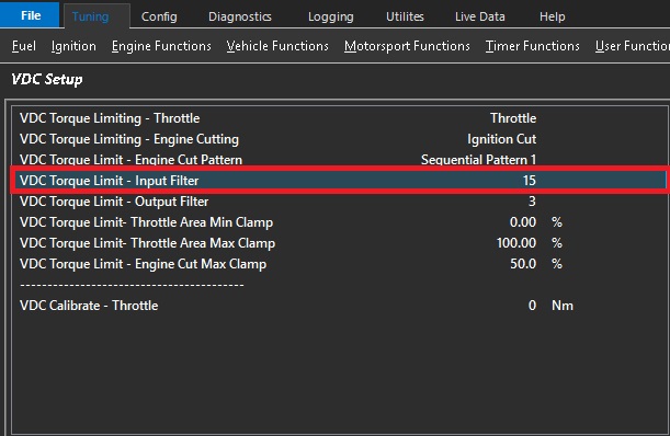
A VDC Torque Limit (Nm) gets converted by the ECU into a Throttle Area output called “Throttle Area Demand - VDC”.
The ECUs uses complex Throttle Mass Flow calculations which are influenced strongly by the Pressure Ratio inputs before
and after the throttle plate. This filter gets applied to this ratio and is used to smooth the input torque requests.
0 = OFF (more aggressive VDC Control)
15 = Max Filtering
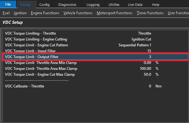
A VDC Torque Limit (Nm) gets converted by the ECU into a Throttle Area output called “Throttle Area Demand - VDC”.
The output (Throttle Area) can be filtered by adjusting this setting before its used to control the Throttle Plate Area.
0 = OFF (more aggressive VDC Control)
5 = Max Filtering
Plot “Throttle Area Demand %” (filtered value) vs “Throttle Area Demand - VDC” (raw unfiltered) for tuning and to see
the filtering effects.
This can be used to smooth the throttle area demand %.
Increasing the filter will smooth the throttle demand.
However it is important to understand that any filter will reduce the response of the system.
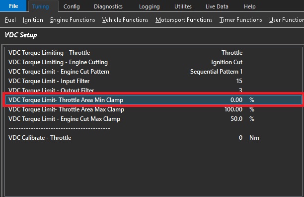
The VDC Torque Limit (Nm) with Throttle Plate control uses Throttle Mass
Flow calculations to derive the required Throttle Area for a given Torque Target.
This setting controls the Minimum amount of Throttle Area the ECU can apply for a given Torque Limit request.
0% = OFF
Example.: 60%
This means the Throttle Area is clamped between 60% and Max%
This is the minimum throttle area % that the system can apply during the VDC event.
Increasing this will cause the VDC system to favor more cutting to reduce torque to the request target.
An extreme of this setting would be 100% which means the throttle is not able to reduce.
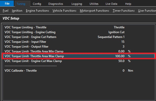
The VDC Torque Limit (Nm) with Throttle Plate control uses Throttle Mass
Flow calculations to derive the required Throttle Area for a given Torque Target.
This setting controls the Max amount of Throttle Area the ECU can apply for a given
Torque Limit request.
0% = OFF
Example.: 90%
This means the Throttle Area is clamped between Min% Value and 90%.
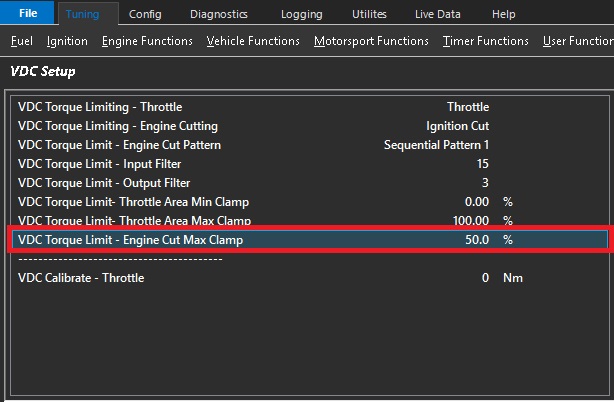
A VDC Torque Limit (Nm) using Engine Cutting gets converted by the ECU into a calibrated
Percentage
This setting controls the Maximum amount of Cut the ECU can apply for a given
Torque Limit request.
Example.: 50%
This means the Maximum Cut applied to the Engine will be clamped to 50%
This is set to 50% by default
Note: In situations where the torque is unable to meet the request target fast enough or at all, this setting would need to be increased. Lowering this setting will cause the VDC system to favor more throttle reduction.
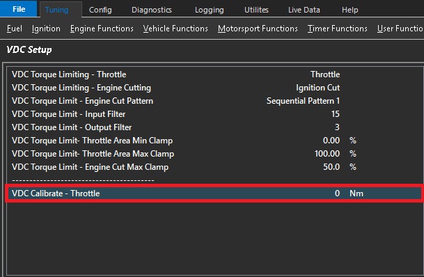
CAUTION The setting will override the Throttle Plate control and reduce the Throttle Area to achieve the entered Torque value.
The setting allows the VDC system to be calibrated and should be done so in a controlled environment only and preferably on a dynamometer.
ONLY becomes active when VDC Calibrate Throttle Area < Pedal Throttle Area Request
0 = OFF
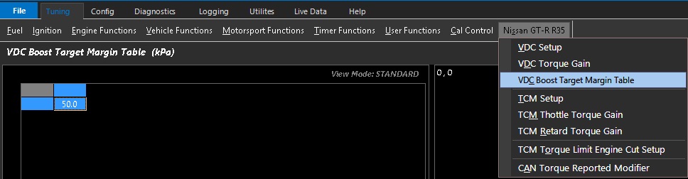
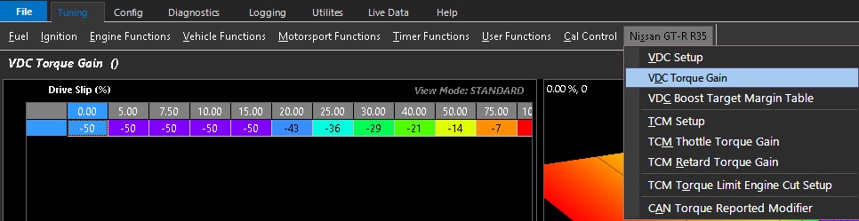
The transmission control module is responsible for anything related to the transmission.
The ECU does not control any part of the transmission,
However, it is responsible for obeying torque requests accurately which are sent to it via the CAN bus.
The ECU is responsible for reducing torque by closing the throttle and by retard.
Emtron has the ability to adjust torque requests requested by the TCM.
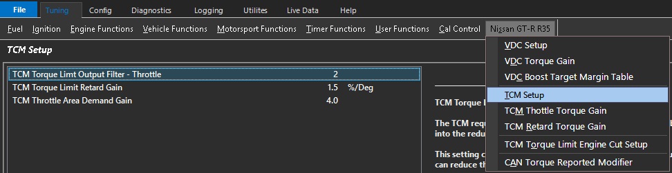
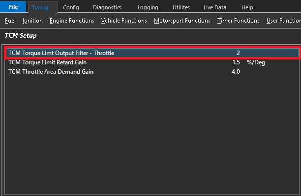
The TCM requests a Torque Limit (Nm) which gets converted by the ECU
into the reduced Throttle Area called “Throttle Area Demand - TCM”
This setting controls the rate at which the TCM Throttle Torque Limit
can reduce the Throttle Area Demand.
0 = OFF (more aggressive TCM Control)
5 = Max Filtering
Plot “Throttle Area Demand %” vs “Throttle Area Demand - VDC” for tuning.
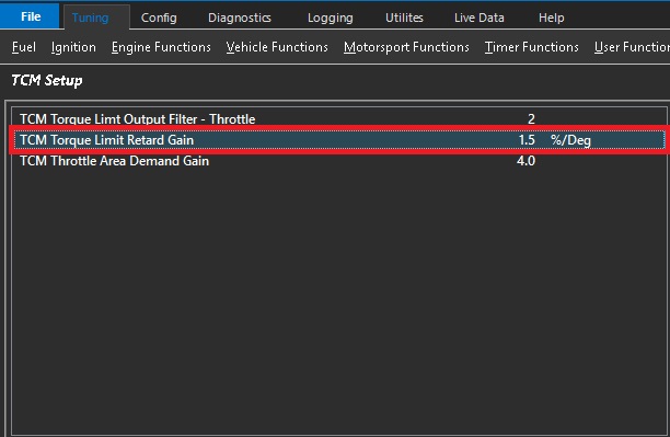
During a TCM Torque Reduction request the ECU can retard the timing to reduce Torque.
This setting indicates to the ECU the percentage of Torque reduced for every 1%/ Deg of Ignition Retard.
Example 1.5%/ Deg.
The Engine is running at 600Nm and a Torque
Reduction to 400Nm is requested.
This is a 33% reduction in Torque so at 1.5%/Deg
the ECU will Retard the Ignition 22 Degrees.
(33% / 1.5%/deg = 22 Deg)
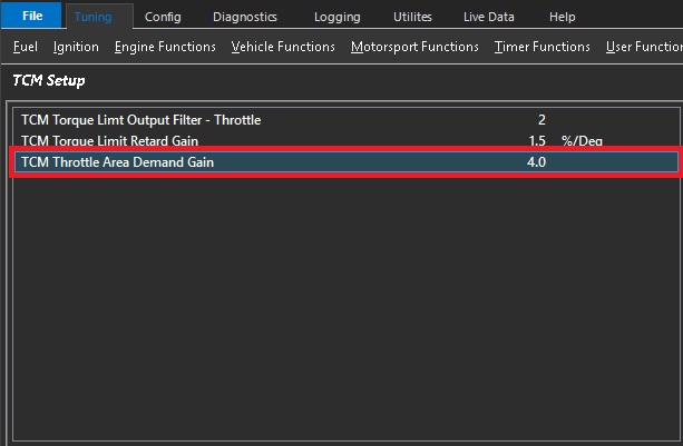
When the current Engine Torque is less than the TCM Torque Demand the Throttle Area will need to be increased.
To overcome inertia and other factors the plate needs to be momentary increased before it comes back to its calculated position.
This setting is primarily used in Launch Control to ensure the ECU tracks the TCM Torque Demand
Gain 0 = OFF
Gains up to the maximum of 5 can achieve good results.
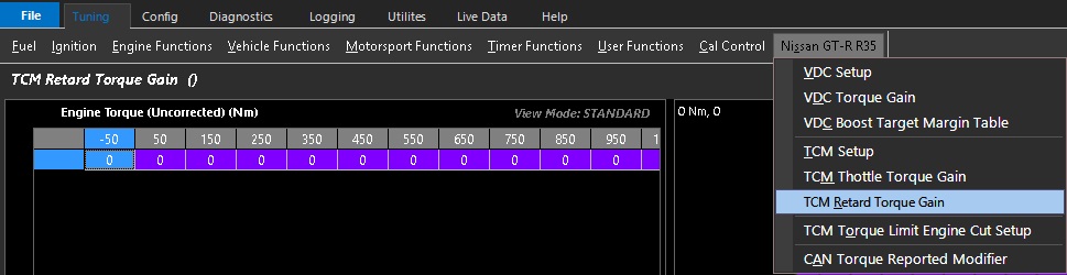
In some motorsport environments and extremely high-end applications the OEM Torque Reductions may not deliver maximum performance. This has been addressed by allowing the user the ability to leverage the factory torque requests and applying a cut for more instantaneous torque reduction.
This is particularly useful on gear shifts where sharper than factory shift response is required.
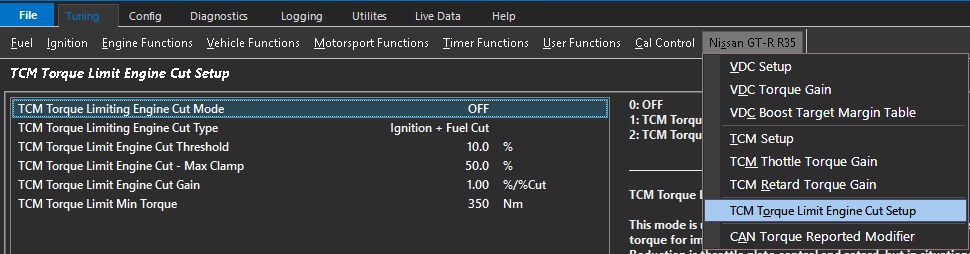
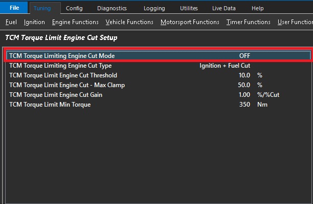
0: OFF
1: TCM Torque Limit Ref: Throttle
2: TCM Torque Limit Ref: Retard
This mode is used to assist the TCM and ECU in reducing the engines torque for improved gearshift control.
The primary source of Torque Reduction is throttle plate control and retard, but in situations of a large torque reduction, the addition of engine cutting can be used to help this process.
The TCM Sends torque limit requests using either Throttle or Retard.
Either torque value can be selected as the reference for the engine cutting calculation.
ONLY gets applied on the Up-shift
A minimum Engine Torque lockout is used to prevent the cut operating under light loads
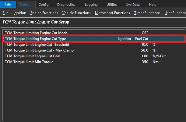
0: Ignition Cut
1: Fuel Cut
2: Ignition + Fuel Cut
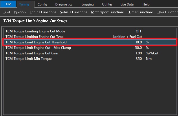
This mode is used to assist the TCM and ECU in reducing the engines torque for improved gearshift control.
The ECU converts the Torque Limit (Nm) sent by the TCM into a calibrated Engine Cut Percentage.
This setting controls the Torque Threshold above which Engine Cutting can be used to reduce torque
Example.:
Cut Threshold 10%
TCM Requesting Torque Limit of 300Nm.
Engine Torque 600Nm
10% of 300Nm = 330Nm
The ECU will calculate the required cut % from 600Nm down to 330Nm.
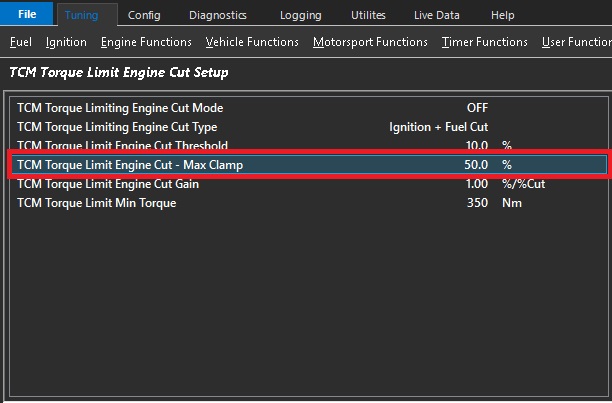
This mode is used to assist the TCM and ECU in reducing the engines torque for improved gearshift control.
The primary source of Torque Reduction is the closing of the throttle plate, but in situations of a large torque reduction,
Ignition cutting can be used to help this process.
The ECU converts the Torque Limit (Nm) into a calibrated Engine Cut Percentage.
This setting controls the Maximum amount of Cut the ECU can apply for a given Torque Limit request.
Example: 50%
This means the Maximum Cut applied to the Engine will be clamped to 50%.
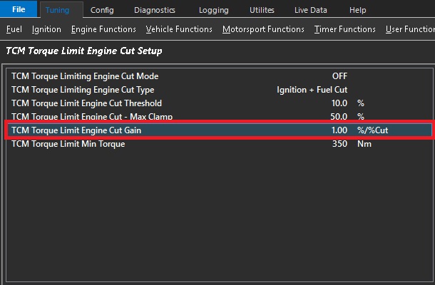
During a TCM Torque Reduction request the ECU can cut the engine to reduce Torque.
This setting indicates to the ECU the percentage of Torque reduced for every 1% of Engine Cut.
Example.
Engine Torque at 600Nm.
200Nm Torque Reduction is requested.
This is a 33% Reduction in Torque
1.0 %/ %Cut. ECU will cut engine at 33%
0.8 %/ %Cut. ECU will cut engine at 41%
1.2 %/ %Cut. ECU will cut engine at 27%
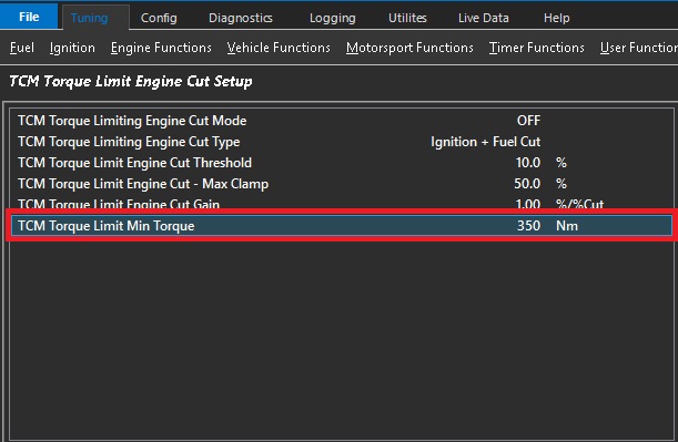
The Uncorrected Engine Torque must be greater than the entered value for the Engine Cut to be enabled