Subaru STi/WRX 06-15
Subaru STi/WRX 06-15 Plug-in ECU User Manual
1.0 Introduction
The Subaru STi MY06-07 and Subaru MY08-15 Plugin ECUs are designed to be plugged into the OEM harness to allow for a true “Plug and Play” install. Both models are almost identical; however, purchase of the correct unit for your model is essential to ensure correct operation. The unit is also compatible with the WRX throughout MY06-07 and MY08-15. Field testing indicates the ECU will also work on MY16-MY17 models, however full support has not been confirmed at the time of writing.
The system is based on the KV Series Motorsport ECU, so all the same features are available with the limitation based around the OEM connector system. An Expansion loom is included giving access to unused Input channels. CAN Bus 2 is also available, operating independently to the OEM Bus, providing additional I/O expandability.
2.0 Plugin Features
General
- KV8 ECU based platform — Dual 100MHz processors, 32MB ECU logging memory, over 1000 channels, 1Hz to 500Hz logging rate
- Aluminium 6061 Grade CNC billet enclosure
- Fully compatible with all OEM systems and user programmable
- Compatible with all Emtron proven motorsport features (Launch Control, Rolling Launch, Anti-Lag, Traction Control)
- Upgradeable to run the Emtron fuel model through installation of a flex meter, fuel temperature and fuel pressure sensor
- Idle speed closed loop control using DBW with advanced Throttle Mass Flow (TMF) airflow calculations
- Knock control with high speed digital filtering for each cylinder using the OEM sensor with selectable centre frequency and bandwidth
- Pre-configured calibration file loaded providing a comprehensive tuning platform
- Input Expansion Capabilities through DTM connector: 3× User Analog Volt Inputs (Fuel Temperature, Fuel Pressure, Inlet Temperature), 1× User Digital Input (Flex Meter Input)
- Emtune software for tuning and data analysis
Communications: CAN 2.0B Node 1 — 500k Baud Full CAN Bus OEM Integration (ABS, SI Drive, DCCD); CAN 2.0B Node 2 — User CAN Bus for I/O expansion (Lambda, EGT); High Speed Ethernet 100Mbps.
Operating Temperature: -30 to 85°C (-22 to 185°F)
Physical: Enclosure Size 160 × 162 × 38 mm, 890g
3.0 Installation
3.1 Expansion Loom
The ECU’s input capabilities can be expanded using the expansion connection, which is a male DTM 12 Way. These additional inputs can be connected to any sensor, but the recommended sensors are indicated in brackets.
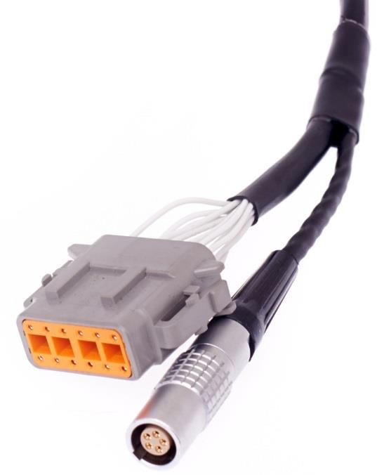
Figure 3.0 — DTM 12 Way expansion loom connector (ECU side).
Table 3.0 — Expansion Port Pinout (DTM06-12SA)
| Pin | Function |
|---|---|
| 1 | Analog Sensor 0V Reference |
| 2 | 5V Vref2 Supply |
| 3 | AN 8 (e.g. Fuel Temp or Inlet Temp) |
| 4 | AN 9 (e.g. Fuel Temp or Inlet Temp) |
| 5 | AN 10 (e.g. Fuel Pressure) |
| 6 | DI 6 (e.g. Ethanol Content Sensor) |
| 7 | 14V Out Protected (e.g. ELC2 Power Supply) |
| 8 | Ground (e.g. ELC2 or E85 Sensor Ground) |
| 9 | Not Used |
| 10 | Not Used |
| 11 | CAN 2 Hi |
| 12 | CAN 2 Lo |
3.2 CAN Bus 2 Wiring
The ECU CAN Bus 2 is reserved for Emtron CAN Bus devices, expanding the IO capability of the ECU. The following devices can be connected: ELC1/2 (Lambda to CAN), ETC4/ETC8M (Thermocouple to CAN), EIC10/EIC16M (Input to CAN).
NoteNOTE ECU CAN Bus 2 operates independently to the OEM CAN Bus 1.
Table 3.1 — CAN Device Power and CAN Deutsch Connector Pinout
| Pin | Function | Wire Colour |
|---|---|---|
| 1 | Ground | BLACK |
| 2 | CAN Lo | GREEN |
| 3 | CAN Hi | YELLOW |
| 4 | 12V Supply | RED |
To help with installation time, each CAN Device pin can be directly connected into the ECU IO Expansion loom:
Table 3.2 — IO Expansion to CAN Device wiring
| Name | ECU IO Expansion 12-Way DTM | CAN Device 4-Way DTM |
|---|---|---|
| Ground | Pin 8 | Pin 1 |
| CAN 2 Lo | Pin 12 | Pin 2 |
| CAN 2 Hi | Pin 11 | Pin 3 |
| Power | Pin 7 | Pin 4 |
Standard CAN bus precautions apply — twisted pair (min one twist per 40mm), minimise connectors, 120 ohm 0.25W termination at each END, stub length < 0.3m (ISO 11898). All Emtron CAN devices have no on-board terminating resistor, allowing them to be wired at any position on the Bus.
3.3 Sensor Wiring
5V VRef2 Sensor Supply (Pin 2 of Expansion loom) — A 250mA 5V output designed to supply automotive sensors.
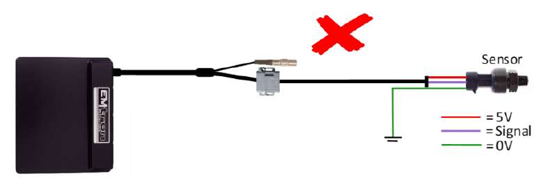
Sensor 0V Reference (Pin 1 of Expansion loom) — This pin should be connected directly to the 0V (Ground) pin on any low current analog sensor, for example Pressure or Temperature.
- DO NOT connect the 0V Reference pin directly to the Engine Block or ECU Ground. This is a dedicated and specialised 0V/ground output for analog sensors.
- DO NOT connect frequency-based sensor grounds to the 0V Reference pin; for example, an Ethanol content sensor. Use Pin 8 (Ground) in the Expansion Loom.
Figure 3.3 — Correct Pressure Sensor 0V wiring (direct to the Sensor 0V Reference). Figure 3.4 — Incorrect Pressure Sensor 0V wiring.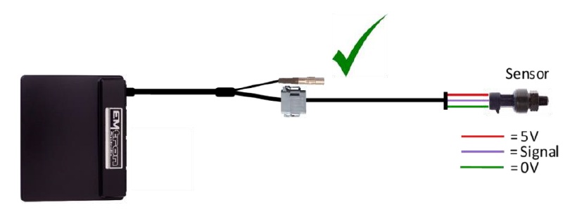
4.0 ECU Channel Assignment
Injection
| ECU Channel | Function |
|---|---|
| Injection 1-4 | Fuel Injector Cyl 1-4 |
| Injection 5 | Rear Lambda Heater |
| Injection 6 | DBW Relay |
| Injection 7 | Purge Solenoid 1 |
| Injection 8-12 | Not Used |
Ignition
| ECU Channel | Function |
|---|---|
| Ignition 1-4 | Ignition Cylinder 1-4 |
| Ignition 5 | Alternator Load Control |
| Ignition 6 | AC Fan Relay |
| Ignition 7 | Engine Fan Relay |
| Ignition 8 | AC Clutch Relay |
| Ignition 9-12 | Not Used |
Analog Inputs
| ECU Channel | Function |
|---|---|
| Analog Voltage 1 | MAP |
| Analog Voltage 2 | TPS (Main) |
| Analog Voltage 3 | TPS (Sub) |
| Analog Voltage 4 | MAF |
| Analog Voltage 5 | O2 Rear Narrow Band |
| Analog Voltage 6 | TGV RH Position |
| Analog Voltage 7 (Pull-up) | Engine Temperature |
| Analog Voltage 8 (Pull-up) | IO Expansion loom (Inlet Temperature) |
| Analog Voltage 9 (Pull-up) | IO Expansion loom (Fuel Temperature) |
| Analog Voltage 10 (Pull-up) | IO Expansion loom (Fuel Pressure) |
| Analog Voltage 11 (Pull-up) | Intake Temperature in MAF |
| Analog Voltage 12 (Pull-up) | TGV LH Position |
| Analog Voltage 13 | Pedal Position (Main) |
| Analog Voltage 14 | Pedal Position (Sub) |
Analog Voltage Channels 7-12 have switchable pull-ups suitable for temperature measurement.
Digital Inputs
| ECU Channel | Function |
|---|---|
| Digital Input 1 | Cam Position - Inlet RH |
| Digital Input 2 | Cam Position - Exhaust LH |
| Digital Input 3 | Cam Position - Exhaust RH |
| Digital Input 4 | Neutral Switch |
| Digital Input 5 | AC Pressure Switch |
| Digital Input 6 | IO Expansion Loom (Ethanol Sensor) |
| Digital Input 7 | Power Steer Pressure Switch |
| Digital Input 8 | AC Switch (non-CAN bus) |
| Digital Input 9 | Clutch Switch |
| Digital Input 10 | Secondary Air Pipe Pressure Signal |
| Digital Input 11 | Brake Switch |
| Digital Input 12 | Start-Stop Switch / Start Position Switch |
| Digital Input 13 | Cruise Command Switch |
| Digital Input 14 | Cruise Switch Main |
Auxiliary Outputs
| ECU Channel | Function |
|---|---|
| Auxiliary 1 | AVCS Solenoid Inlet LH |
| Auxiliary 2 | AVCS Solenoid Inlet RH |
| Auxiliary 3 | AVCS Solenoid Exhaust LH |
| Auxiliary 4 | AVCS Solenoid Exhaust RH |
| Auxiliary 5 | Wastegate Solenoid |
| Auxiliary 6 | Tacho |
| Auxiliary 7 | Fuel Pump Speed Control |
| Auxiliary 8 | Check Engine Light (non-CAN bus) |
| Auxiliary 9 | DBW + |
| Auxiliary 10 | DBW - |
| Auxiliary 11 | TGV LH Motor + (LH- & RH+ linked in series) |
| Auxiliary 12 | TGV RH Motor - |
| Auxiliary 13 | Accessory Cut Relay |
| Auxiliary 14 | Starter Relay |
| Auxiliary 15 | Secondary Air Pump Relay |
| Auxiliary 16 | Secondary Comb. Valve Relay (LH Head - 5 wire) |
Crank / Cam
| ECU Channel | Function |
|---|---|
| Crank Index | Crank Sensor |
| Sync Sensor | Cam Position - Inlet LH |
5.0 Plug-in Specific Information
5.1 Fuel Model
The ECU can be tuned using one of the many fuel models available. Speed Density (MAP Sensor) or Mass Air Flow (MAF Sensor) are the two most common. The Fuel Model can be adjusted using Emtune → Config View → Fuel → Fuel Main → Fuel Model Setup.
- When Speed Density is selected, Fuel Table 1 is used for VE correction.
- When MAF is selected, the Secondary Load table can be used to scale the MAF if required. This table will need to be switched ON via Fuel Menu → Fuel Table Control → Secondary Load Table (set to a value of 12).
There is also a runtime in the F3 Menu → Fuel Tab showing the current Fuel Model the ECU is running in.
5.2 Inlet Air Temperature
Some STi models have a factory-fitted Inlet Temperature Sensor, available on Analog Input 8. If this sensor is available, the “Inlet Air Temperature” should have the Input Source selected to ANV8. On models without an Inlet Temperature Sensor there are two options:
- Fit an Inlet Temperature Sensor and use the expansion port to bring the signal into the ECU (AN8 and Sensor Ground).
- Use the MAF Temp to approximate the Inlet Temperature (the default setting), adjustable via Emtune → Config View.
5.3 Tumbler Generator Valves (TGV)
The LH and RH valves are connected in series and controlled using Auxiliary Channels 11 and 12. The control strategies are locked:
- The valves are either fully open or fully closed.
- When Engine Temperature is less than 60°C the valves are always Closed at key-on. Once the engine is started they remain closed until the Pedal Position goes above 2.0%, at which point they open and remain open.
- When Engine Temperature is above 60°C the valves always Open at key-on.
- The valves are modulated at 10Hz, 50% DC to ensure they don’t move during normal driving conditions.
As these valves significantly affect the VE of the engine when closed, the Fuel User Comp Table 1 can be used to adjust fuelling. If the TGV valves have been removed, switch the function off from Config View → Functions → Engine Functions and zero all fuel corrections in the User Comp Table 1.
5.4 SI Drive
When available, the position of the SI Drive is read from the CAN Bus and used to select the ECU’s Cal Slot position. Positions 1-4 are available. The default Cal File is set up to switch to Requested Torque Tables (see Tuning View → Cal Control for more options).
| SI Drive Mode | ECU Value | Cal Slot Position | Requested Torque Table |
|---|---|---|---|
| OFF (no SI Drive) | 0 | 1 | Table 1 |
| Sports Sharp (S#) | 1 | 2 | Table 1 |
| Intelligent (I) | 2 | 3 | Table 2 |
| Sports (S) | 3 | 4 | Table 3 |
5.5 Push Button Start vs Key Start
A change to the Cal file is required based on whether the vehicle has a Button Start or Key Start.
5.5.1 Push Button Start — Auxiliary Channel 14 controls the starting of the engine. When the output is Low the engine will crank, so the ECU must control starting using the “Engine Start Control” function. In Config View → Functions → Vehicle Functions 2 → Engine Start Control: set “Engine Starter Output” channel to Auxiliary 14 and “Engine Immobiliser Output” to OFF. In Config View → Input → Switches: set “Start/Stop Switch” Input Source to DI12 and “Start Position Switch” to OFF.
5.5.2 Key Start — On key-start vehicles, Auxiliary Channel 14 prevents the engine starting when the key is moved to the start position (immobiliser function — when the output is Low/at ground the engine will not start). In Engine Start Control: set “Engine Starter Output” to OFF and “Engine Immobiliser Output” to Auxiliary 14. In Switches: set “Start/Stop Switch” to OFF and “Start Position Switch” to DI12.
The Engine Start settings can be adjusted from Tuning View → Vehicle Functions → Engine Start Control.
5.6 Check Engine Light
Control of this light is done either through the CAN bus or Auxiliary Channel 8. The default Cal file has the Output Channel selected on CAN Bus OEM. This can be adjusted from Config View → Functions → Vehicle Functions 1.
5.7 AirCon Switch
The AirCon Switch status is read either through the CAN bus or Digital Input 8. The default Cal file has the Input Source selected on CAN Bus OEM. This can be adjusted from Config View → Inputs → Input Pins Setup → Switches.
6.0 Diagnostic Trouble Codes (DTCs)
On initial installation it is advised to clear all the DTCs if errors are reported. Connect to Emtune and look at the DTC status in the bottom toolbar (red if errors are present). Open the DTC window via the DTC Status box or File → Open DTC, select “Clear ALL DTCs”, and confirm all the Error Codes have been removed (status box goes green). If the error codes have not all been removed, select “Update DTC” then use the DTC window to locate the sensor that is on fault.
7.0 OEM CAN Bus 1
The ECU communicates on CAN Bus 1, which is reserved for the Subaru OEM Bus. The ECU maintains full compatibility with all other CAN devices within the vehicle. The CAN bus protocol is defined by year and divided into 5 groups:
- Subaru Liberty MY10 (option 16)
- Subaru STi MY15+ JDM (option 17) — NOTE: JDM and ADM are different.
- Subaru STi MY15+ ADM (option 18)
- MY12-MY14 (option 19)
- MY07-MY11 (option 20)
This setting can be adjusted from Config View → Communications → CAN Bus 1 → Channel 1 → DATA Set. The Input Source should be selected to “CAN Bus OEM” for a channel to receive this data.
Table 7.0 — Subaru received OEM CAN data
| ECU Channel Name | Description |
|---|---|
| Vehicle Speed | The average speed of the front wheels |
| Drive Speed Front L/R | Wheel Speed Front Left / Right |
| Drive Speed Rear L/R | Wheel Speed Rear Left / Right |
| Steering Angle | Steering angle in degrees (negative left, positive right) |
| Front Brake Pressure | Front brake pressure (Bar) |
| AirCon Switch | AirCon Off/On Switch |
| AC Evap Temp Switch | AirCon Evaporator switch used by the ECU to control the AC Clutch |
| Traction Control Switch | Traction Control Off/On Switch |
| SI Drive | The ECU reads 1 of 3 modes: Sports, Intelligent, Sports Sharp |
8.0 Ordering Information
| Product | Part Number |
|---|---|
| Emtron Subaru STi 06-15 Plugin | 1609-192015 |
Appendix A – ECU Pinout
Connector B134
| Pin | Function | Channel Assignment |
|---|---|---|
| B134-5 | Engine Block/Power Ground | |
| B134-6 | Manifold Pressure Sensor Signal | ANV1 |
| B134-7 | ECU 14V from Main Relay | |
| B134-11 | Cam Inlet RH Signal (Hall) | DI 1 |
| B134-12 | Cam Exhaust RH Signal (Hall) | DI 2 |
| B134-13 | Crank Position Sensor (+) | Crank Index +ve |
| B134-14 | Crank Position Sensor (-) | Crank Index -ve |
| B134-15 | Knock Sensor Signal | Knock 1 +ve |
| B134-16 | TGV LH Position Signal | ANV 12 |
| B134-18 | DBW Position Main Signal | ANV 2 |
| B134-19 | +5V Eng (MAP, DBW Pos, FPS, TGV Pos, Sec Air Pres) | |
| B134-21 | Cam Inlet LH Signal (Hall) | Sync Sensor |
| B134-22 | Sensor Ground Out (Inlet, Exhaust LH/RH Cam Position) | |
| B134-24 | SHIELD - Crank Position Sensor | |
| B134-25 | SHIELD - Knock Sensor | |
| B134-26 | TGV RH Position Signal | ANV 6 |
| B134-27 | Secondary Air Pipe Pressure Signal | DI 10 |
| B134-28 | DBW Position Sub Signal | ANV 3 |
| B134-29 | Sensor Ground Out (MAP, TPS, ET, DBW, TGV, Knock, Sec Air) | |
| B134-31 | Cam Exhaust LH Signal (Hall) | DI 2 |
| B134-33 | Power Steer Oil Pressure Switch | DI 7 |
| B134-34 | ET Sensor | ANV 7 |
Connector B135
| Pin | Function | Channel Assignment |
|---|---|---|
| B135-1 | SHIELD - Front and Rear Oxygen Sensor | |
| B135-2 | ECU 14V from Main Relay | |
| B135-3 | Accessory Cut Relay | |
| B135-4 | Rear Oxygen Sensor Signal | ANV 5 |
| B135-5 | Backup Power / Batt Constant | |
| B135-12 | Cruise Control Main Switch | DI 14 |
| B135-13 | Starter Switch 2 | DI 12 |
| B135-18 | Intake AT Sensor Signal (In MAF) | ANV 11 |
| B135-19 | Ignition Switch | IGN SW |
| B135-20 | Brake Switch 1 (Normally Closed) | DI 11 |
| B135-21 | +5V Eng Supply – FPS Main | +5V Supply |
| B135-22 | 5V Eng Supply – FPS Sub | +5V Supply |
| B135-23 | FPS Signal – Main | ANV 13 |
| B135-24 | Cruise Command Switch (Set/Resume/Coast/Res/Cancel) | DI 13 |
| B135-26 | Air Flow Sensor Signal | ANV 4 |
| B135-29 | FPS Main Sensor Ground | |
| B135-30 | Sensor Ground Out | |
| B135-31 | FPS Signal – Sub | ANV 14 |
| B135-34 | Air Flow Sensor Ground | |
| B135-35 | SHIELD – Air Flow Sensor |
Connector B136
| Pin | Function | Channel Assignment |
|---|---|---|
| B136-1 | DBW Power (From DBW Relay) | |
| B136-2 | Front Oxygen Heater Signal 2 | |
| B136-3 | Front Oxygen Heater Signal 1 | |
| B136-4 | Rear Oxygen Heater | |
| B136-6 | SHIELD – FPS, TPS Main, Neutral Sw | |
| B136-9 | A/C Clutch Relay | IGN 8 |
| B136-10 | Alternator Load Control | IGN 5 |
| B136-11 | CEL (Non CAN Bus) | |
| B136-12 | FPC Unit - Control Signal | AUX 7 |
| B136-18 | Sub Fan Relay Control | IGN 6 |
| B136-20 | Starter Relay Inhibit | |
| B136-21 | DBW Power Control Relay | INJ 6 |
| B136-22 | Engine Speed Output (Tacho) | AUX 6 |
| B136-23 | Main Relay Control | Main Relay Control |
| B136-24 | A/C Request Switch (Non CAN Bus) | DI 8 |
| B136-25 | Clutch Switch | DI 9 |
| B136-27 | CAN + (500kBaud) | |
| B136-29 | Main Fan Relay Control | IGN 7 |
| B136-31 | Neutral Position Switch | DI 4 |
| B136-32 | Start/Stop Button | DI 12 |
| B136-35 | CAN - (500kBaud) |
Connector B137
| Pin | Function | Channel Assignment |
|---|---|---|
| B137-1 | Engine Block/Power Ground | |
| B137-2 | Engine Block/Power Ground | |
| B137-3 | Engine Block/Power Ground | |
| B137-4 | DBW Motor + | AUX 9 |
| B137-5 | DBW Motor - | AUX 10 |
| B137-6 | Ignition Coil Ground | |
| B137-7 | Engine Block/Power Ground | |
| B137-8 | Injector Cylinder 1 | INJ 1 |
| B137-9 | Injector Cylinder 2 | INJ 2 |
| B137-10 | Injector Cylinder 3 | INJ 3 |
| B137-11 | Injector Cylinder 4 | INJ 4 |
| B137-12 | TGV LH Motor (+ to open) | AUX 11 |
| B137-13 | TGV LH Motor (- to close) | AUX 12 |
| B137-14 | AVCS Inlet LH Solenoid - | AUX 1 |
| B137-15 | AVCS Inlet LH Solenoid + | |
| B137-16 | AVCS Inlet RH Solenoid - | AUX 2 |
| B137-17 | AVCS Inlet RH Solenoid + | |
| B137-18 | Ignition Cylinder 1 | Ign 1 |
| B137-19 | Ignition Cylinder 2 | Ign 2 |
| B137-20 | Ignition Cylinder 3 | Ign 3 |
| B137-21 | Ignition Cylinder 4 | Ign 4 |
| B137-22 | TGV RH Motor (+ to open) | AUX 11 |
| B137-23 | TGV RH Motor (+ to close) | AUX 12 |
| B137-24 | AVCS Exhaust RH Solenoid - | AUX 4 |
| B137-25 | AVCS Exhaust RH Solenoid + | |
| B137-26 | Ignition Coil Ground | |
| B137-27 | Wastegate Control Solenoid | AUX 5 |
| B137-29 | Purge Control Solenoid Valve #1 | INJ 7 |
| B137-30 | AVCS Exhaust LH Solenoid - | AUX 3 |
| B137-31 | AVCS Exhaust LH Solenoid + |