Toyota GT86 / Subaru BRZ / Scion FR-S
GT86/BRZ/FR-S Plug-in ECU User Manual
1.0 Introduction
The Toyota/Subaru GT86/BRZ/FR-S features a flat-four configuration engine that employs an interesting combination of four (4) direct injectors and four (4) port injectors for fuel. The ECU must be able to control both types of injector along with accurately controlling the GDI pump pressure to a target. GDI pressures operate significantly higher than a conventional port injection system.
To correctly calculate the fuelling requirements the ECU is able to accept sensor inputs from the MAF Meter and/or MAP sensor depending on the fuel model mode selected.
This manual does not cover ECU installation.
2.0 Plugin Features
General
- KV12 ECU based platform — Dual 100MHz processors, 32MB ECU logging memory, over 1000 channels, 1Hz to 500Hz logging rate
- Emtune Software for tuning and data analysis; Knock Control using digital filtering with Bosch technology
- 6061 Grade Aluminium CNC Billet Enclosure
- Fully compatible with all OEM systems and user programmable, including Vehicle Stability Control (VSC) using throttle torque reduction
- Compatible with all Emtron proven motorsport features
- Upgradeable to run the Emtron Fuel model through installation of a Flex Meter, Fuel Temperature and Fuel Pressure Sensor
- Input Expansion Capabilities through DTM connector: 4× User Analog Volt Inputs (Fuel Temperature, Inlet Temp and Pressure), 1× User Digital Input (Flex Meter Input)
- Output Expansion Capabilities through the DTM connector: 1× Auxiliary Output (Boost Control Solenoid)
Communications: CAN 2.0B Node 1 — User CAN Bus for I/O expansion (Lambda, EGT); CAN 2.0B Node 2 — 500k Baud Full CAN Bus OEM Integration; High Speed Ethernet 100Mbps.
Operating Temperature: -30 to 125°C (-22 to 257°F)
Physical: Enclosure Size 160 × 162 × 38 mm, 890g
3.0 Kit Contents
When purchasing a Toyota/Subaru GT86/BRZ/FR-S plug-in the following items are included:
- GT86/BRZ/FR-S Plug-in ECU
- DTM 12 way Female Connector and pin kit
3.1 Expansion Loom
The ECU’s Input capabilities can be expanded using the expansion connection, which is a male DTM 12 Way (DT06-12SA). These additional inputs can be connected to any sensor, but the recommended sensors are indicated in brackets.
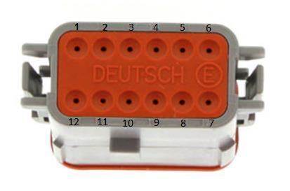
Expansion port connector DT06-12SA (ECU side). Mating connector (car side): DT04-12PA.
Table 3.0 — Expansion Port Pinout
| Pin | Function |
|---|---|
| 1 | Analog Sensor 0V Reference |
| 2 | 5.0V Aux Supply |
| 3 | AN 8 (e.g. Fuel Temp or Inlet Temp) |
| 4 | AN 9 (e.g. Fuel Temp or Inlet Temp) |
| 5 | AN 10 (e.g. Fuel Pressure) |
| 6 | DI 6 (e.g. Ethanol Content Sensor) |
| 7 | 14V Out Protected (ELC1 Power Supply) |
| 8 | Ground (ELC1 Ground) |
| 9 | Auxiliary Output 5 (e.g. Boost Control solenoid) |
| 10 | NC |
| 11 | CAN 1 Hi |
| 12 | CAN 1 Lo |
To minimise signal contamination and maximise noise immunity, twist the CAN High and CAN Low wire pair at a minimum of one twist per 40mm of cable.
4.0 ECU Channel Assignment
Injection
| ECU Channel | Function |
|---|---|
| Injection 1-4 | Port Fuel Injector Cyl 1-4 |
| Injection 5 | Rear Lambda Heater |
| Injection 6 | Purge |
| Injection 7 | DBW Power Supply Relay |
| Injection 8 | Direct Injection Power Supply Relay |
| Injection 9-12 | DI Fuel Injector Cyl 1-4 |
Ignition
| ECU Channel | Function |
|---|---|
| Ignition 1-4 | Ignition Cylinder 1-4 |
| Ignition 5 | Alternator Control |
| Ignition 6 | Engine Fan Relay |
| Ignition 7 | AC Clutch Relay |
| Ignition 8 | Starter Relay (Push Start) / Start Inhibit (Key Start) |
| Ignition 9-10 | Not Used |
| Ignition 11 | DI Fuel Pump Control |
| Ignition 12 | Not Used |
Analog Inputs
| ECU Channel | Function |
|---|---|
| Analog Voltage 1 | MAP |
| Analog Voltage 2 | DBW 1 Servo Position Main |
| Analog Voltage 3 | DBW 1 Servo Position Sub |
| Analog Voltage 4 | MAF |
| Analog Voltage 5 | Rear O2 Sensor |
| Analog Voltage 6 | IO Expansion Loom (e.g. Fuel Pressure) |
| Analog Voltage 7 (Pull-up) | Engine Temperature |
| Analog Voltage 8-10 (Pull-up) | IO Expansion Loom (IAT / F.Temp / F.Pressure) |
| Analog Voltage 11 (Pull-up) | Intake Temperature MAF |
| Analog Voltage 12 (Pull-up) | Engine Oil Temperature |
| Analog Voltage 13 | Pedal Position Sensor (PPS) Main |
| Analog Voltage 14 | Pedal Position Sensor (PPS) Sub |
Analog Voltage Channels 7-12 have switchable pull-ups suitable for temperature measurement.
Digital Inputs
| ECU Channel | Function |
|---|---|
| Digital Input 1 | Cam Position - Inlet RH |
| Digital Input 2 | Cam Position - Exhaust LH |
| Digital Input 3 | Cam Position - Exhaust RH |
| Digital Input 4 | Neutral Position Switch |
| Digital Input 5 | Direct Injection 1 Feedback |
| Digital Input 6 | IO Expansion Loom (e.g. Ethanol Sensor) |
| Digital Input 7 | Direct Injection 2 Feedback |
| Digital Input 8 | DI Fuel Pump Feedback |
| Digital Input 9 | Clutch Switch |
| Digital Input 10 | Start Signal from Starter Relay (Button Start) / NC (Key Start) |
| Digital Input 11 | AC Pressure (some models only) |
| Digital Input 12 | Start/Stop Switch (Button Start) / Start Signal from Starter Relay (Key Start) |
| Digital Input 13 | Brake Switch |
| Digital Input 14 | Cruise Control Switch |
Auxiliary Outputs
| ECU Channel | Function |
|---|---|
| Auxiliary 1 | VVT Solenoid Inlet RH |
| Auxiliary 2 | VVT Solenoid Inlet LH |
| Auxiliary 3 | VVT Solenoid Exhaust RH |
| Auxiliary 4 | VVT Solenoid Exhaust LH |
| Auxiliary 5 | IO Expansion Loom (e.g. Boost Control Solenoid) |
| Auxiliary 6 | Engine Speed Output |
| Auxiliary 7 | Fuel Pump Speed Control |
| Auxiliary 8 | AC Fan Relay |
| Auxiliary 9 | DBW + |
| Auxiliary 10 | DBW - |
| Auxiliary 11 | Start Inhibit (Button Start) / NC (Key Start) |
| Auxiliary 12 | Not Used |
| Auxiliary 13 | Canister Pump Module Relay (PPMP) |
| Auxiliary 14 | Canister Pump Module Relay (VPMP) |
| Auxiliary 15 | Canister Pump Module Relay (MPMP) |
| Auxiliary 16 | Not Used |
NoteNOTE Auxiliary Channels 13-15 have drivers suitable ONLY for relay control with switching currents that must be less than 0.5A.
Crank / Cam
| ECU Channel | Function |
|---|---|
| Crank Index | Crank Sensor |
| Sync Sensor | Cam Position - Inlet Bank 1 (LH) |
5.0 Plug-in Specific Information
5.2 Fuel Model
The ECU can use many combinations of methods to generate the fuel mass output. The base calibration is supplied using simple but common Speed Density (MAP). Commonly modified camshafts, aftermarket air bypass valves, larger turbochargers and modified intake piping tend to create unstable Mass Flow Sensor readings, so MAP-based fuel models tend to make the process much simpler. (Press F1 with the Fuel Model setting selected for more detailed help.)
When MAF is selected, the Secondary Load table can be used to scale the MAF if required. This table will need to be switched ON via Fuel Menu → Fuel Table Control → Secondary Load Table (set to a value of 12). There is also a runtime in the F3 Menu → Fuel Tab showing the current Fuel Model the ECU is running in.
5.3 Inlet Air Temperature
A factory-fitted Inlet Temperature Sensor is available on Analog Input 11 and should already be configured in the base calibration shipped with the ECU.
5.4 Check Engine Light
The control of this light is done through the CAN bus. The base calibration file has the output already configured and selected to “CAN Bus OEM”.
5.5 AirCon Switch
The AirCon Switch status is read through the CAN bus. The base calibration file has the Input Source selected to “CAN Bus OEM”.
6.0 Diagnostic Trouble Codes (DTCs)
On initial installation it is advised to clear all the DTCs if errors are reported. Connect to Emtune and look at the DTC status in the bottom toolbar (red if errors are present). Open the DTC window via the DTC Status box or File → Open DTC, select “Clear ALL DTCs”, and confirm all the Error Codes have been removed (status box goes green). If the error codes have not all been removed, select “Update DTC” then use the DTC window to locate the sensor that is on fault.
7.0 User CAN Bus 1
The ECU CAN Bus 1 is available for Input/Output expansion, allowing a wide range of Emtron CAN devices to be connected: ELC1/2 (Lambda to CAN), ETC4/ETC8M (Thermocouple to CAN), EIC10/EIC16M (Input to CAN).
7.1 Emtron Lambda to CAN
The ELC uses Bosch proven integrated circuit technology to precisely control an LSU4.9 Lambda sensor. The Lambda value is transmitted over the CAN Bus and can be used by the ECU for tuning and closed loop control. The ELC Power, Ground and CAN wires can be directly connected into the IO Expansion Loom:
Table 7.0 — ELC1 to IO Expansion Port wiring
| Name | ELC 4-Way DTM | ECU IO Expansion 12-Way DTM |
|---|---|---|
| Ground | Pin 1 | Pin 8 |
| CAN Lo | Pin 2 | Pin 12 |
| CAN Hi | Pin 3 | Pin 11 |
| Power | Pin 4 | Pin 7 |
8.0 OEM CAN Bus 2
The ECU communicates on CAN Bus 2, which is reserved for the GT86/BRZ/FR-S. The ECU maintains full compatibility with all other CAN devices within the vehicle, transmitting a wide range of raw and calibrated data over the Bus while also receiving data.
9.0 Emtron Torque Management
The ECU performs extremely accurate torque calculations provided the engine model configuration is accurate. This section allows the user to calibrate any errors in the torque model whilst also influencing the engine torque delivery characteristics.
- 9.1 Torque Reduction Ign Retard Clamp — Limits the maximum torque reduction the ECU can perform based on ignition timing retard.
- 9.2 Torque Nitrous Gain — In applications where Nitrous is used to increase torque, the ECU calculates this torque increase; the gain can be used to trim the output if required.
- 9.3 BSFC — Brake Specific Fuel Consumption torque calculation is not used by the ECU but can be useful, when calibrated correctly, to cross-check the ECU calculated torque levels.
- 9.4 Engine Torque Correction Table — Allows the user to adjust the gain on the calculated Engine Torque based on any parameter in the axis setup form (used to correct calibration errors).
- 9.5 Torque Demand Correction Table — The GT86/BRZ/FR-S requests accurate information on driver-demanded torque so decisions can be made across vehicle systems. If correlation issues exist between reported torque and Torque Demanded, the vehicle will not function as intended and can lead to drivetrain operation issues. This table allows gain control of this channel (should not normally require modification).
- 9.6 Frictional Loss Table — The combustion torque (“Torque Ideal”) is calculated by the ECU; the moving parts create drag and limit available torque. This table allows entry of the frictional loss in Nm.
- 9.7 Frictional Loss Offset 1 Table — One of two tables that allow offsetting of the frictional loss (commonly spanned against Engine Oil Temperature).
- 9.8 Torque Reduction Ignition Retard Gain Table — Calibrates the torque reduction % per degree. When a torque request is applied the ECU calculates how much retard is required to achieve it.
- 9.9 Torque Reduction Gain Table — Calibrates the torque reduction % per %cut. When a torque request is applied the ECU calculates how much cut is required to achieve it.
10.0 Ordering Information
| Product | Part Number |
|---|---|
| Emtron GT86/BRZ/FR-S Plugin | 1609-72086 |
Appendix A – ECU Pinout
Connector A
| Pin | Function | Channel Assignment |
|---|---|---|
| A1 | Throttle Servo Motor - | AUX1012 Supply (option 2) |
| A2 | Throttle Servo Motor + | AUX9 |
| A3 | Power Ground | GND |
| A4 | Power Ground | GND |
| A5 | Cam Solenoid Exhaust RH | Aux 4 |
| A6 | O2 NarrowBand Heater | GROUND |
| A7 | Cam Solenoid Exhaust LH | Aux 3 |
| A8 | Ignition 4 | Ign 4 |
| A10 | Ignition 2 | Ign 2 |
| A11 | Purge | Inj 6 |
| A12 | Injector 1 (Port) | Inj 1 |
| A13 | Injector 4 (Port) | Inj 2 |
| A14 | Injector 1 (Direct) | Inj 1 Direct |
| A16 | Cam Solenoid Inlet RH | Aux 2 |
| A17 | Cam Solenoid Inlet LH | Aux 1 |
| A18 | TPS (Main) | An 2 |
| A19 | 5V Engine (TP and VSV) | Eng 5V |
| A20 | Oil Temperature | An 10 |
| A21 | Ignition 1 | Ign 1 |
| A22 | Injector 2 (Port) | Inj 2 |
| A23 | Injector 4 (Direct) | Inj 4 Direct |
| A24 | Injector 3 (Direct) | Inj 3 Direct |
| A25 | Injector 2 (Direct) | Inj 2 Direct |
| A28 | TPS (Sub) | An 3 |
| A29 | Sensor Ground (Knk, MAF, Oil Temp, Eng Temp) | Sensor 0V Ref |
| A30 | ECT | An 7 |
| A31 | Ignition 3 | Ign 3 |
| A32 | Injector 3 (Port) | Inj 3 |
Connector B
| Pin | Function | Channel Assignment |
|---|---|---|
| B1 | Canister Pump Module (VPMP) | |
| B5 | Direct Injector Power Supply Relay | Inj 8 |
| B7 | DBW (ETCS) Power | Inj 7 |
| B8 | Canister Pump Module (MPMP) | |
| B10 | Fuel Pump Feedback | DI 5 |
| B11 | Cooling Fan Relay 3 | Ign 5 |
| B12 | Cooling Fan Relay 1 2 | Ign 6 |
| B13 | EFI Relay (Gnd) | |
| B15 | Tacho | Aux 6 |
| B17 | DBW Relay (Gnd) | Inj 7 |
| B18 | Alternator Control | Aux 8 |
| B19 | FPC | Aux 7 |
| B20 | Canister Pump Module | GROUND |
| B21 | 5V Eng (FPS Main) | 5V Eng |
| B22 | 5V Eng (FPS Sub) | 5V Eng |
| B23 | FPS Main Signal | An 13 |
| B26 | Starter Relay | Ign 8 |
| B29 | Sensor Ground (PP) | Sensor 0V Ref |
| B30 | Sensor Ground (PP) | Sensor 0V Ref |
| B31 | FPS Sub Signal | An 14 |
| B34 | Start Cut Relay | Aux 11 |
| B35 | AC Clutch | Ign 7 |
Connector C
| Pin | Function | Channel Assignment |
|---|---|---|
| C1 | Power Ground | GROUND |
| C2 | Power Ground | |
| C3 | Power Ground | |
| C5 | O2 Wideband Heater | |
| C6 | 14V ECU Power | |
| C9 | Fuel Pressure Signal | An 6 |
| C11 | DF1 | DI 5 |
| C13 | Fuel Pump Feedback | DI 8 |
| C14 | Exhaust Cam Position (LH) | DI 2 |
| C15 | Intake Cam Position (RH) | DI 1 |
| C16 | Crank Signal + | |
| C17 | Knock Signal (RH) | |
| C18 | O2 Wideband Sensor Signal 1 - | |
| C19 | O2 Wideband Sensor Signal 1 + | |
| C20 | Manifold Pressure Sensor | An 1 |
| C21 | O2 NarrowBand Sensor Signal 2 | |
| C25 | Exhaust Cam Position (RH) | DI 3 |
| C26 | Inlet Cam Position (LH) | Sync Index |
| C27 | Crank Signal - | |
| C28 | Knock Signal LH + | |
| C29 | Shield (Knock) | |
| C30 | Shield (O2) | |
| C31 | DF2 | DI 7 |
| C32 | Fuel Pump Driver | Aux 12 |
| C34 | 5V for CAM Sensors | 5V Eng |
| C35 | Shield (Crank) |
Connector D
| Pin | Function | Channel Assignment |
|---|---|---|
| D1 | 14V ECU Power | |
| D2 | Battery | |
| D3 | Brake Switch (NO) | |
| D4 | Signal Ground / Shielding | |
| D7 | Brake Switch (NC) | DI 13 |
| D8 | AC Pressure Sensor | DI 11 |
| D12 | Intake Temp (MAF) | AN 11 |
| D14 | Starter Signal from Start Relay | DI 10 |
| D15 | Clutch Switch | DI 9 |
| D16 | Neutral Switch | DI 4 |
| D17 | Start Request | DI 12 |
| D18 | CAN Lo | CAN Lo |
| D19 | CAN Hi | CAN Hi |
| D20 | GROUND | |
| D22 | MAF Signal | AN 4 |
| D24 | Battery Current Sensor | GROUND |
| D27 | Ignition Switch | |
| D28 | Shield (MAF) | |
| D29 | Ground (MAF) | |
| D30 | Cruise Switch (Main) | DI 14 |