Subsections of Wiring
KV Series
Subsections of KV Series
KV8 Pinout Rev2
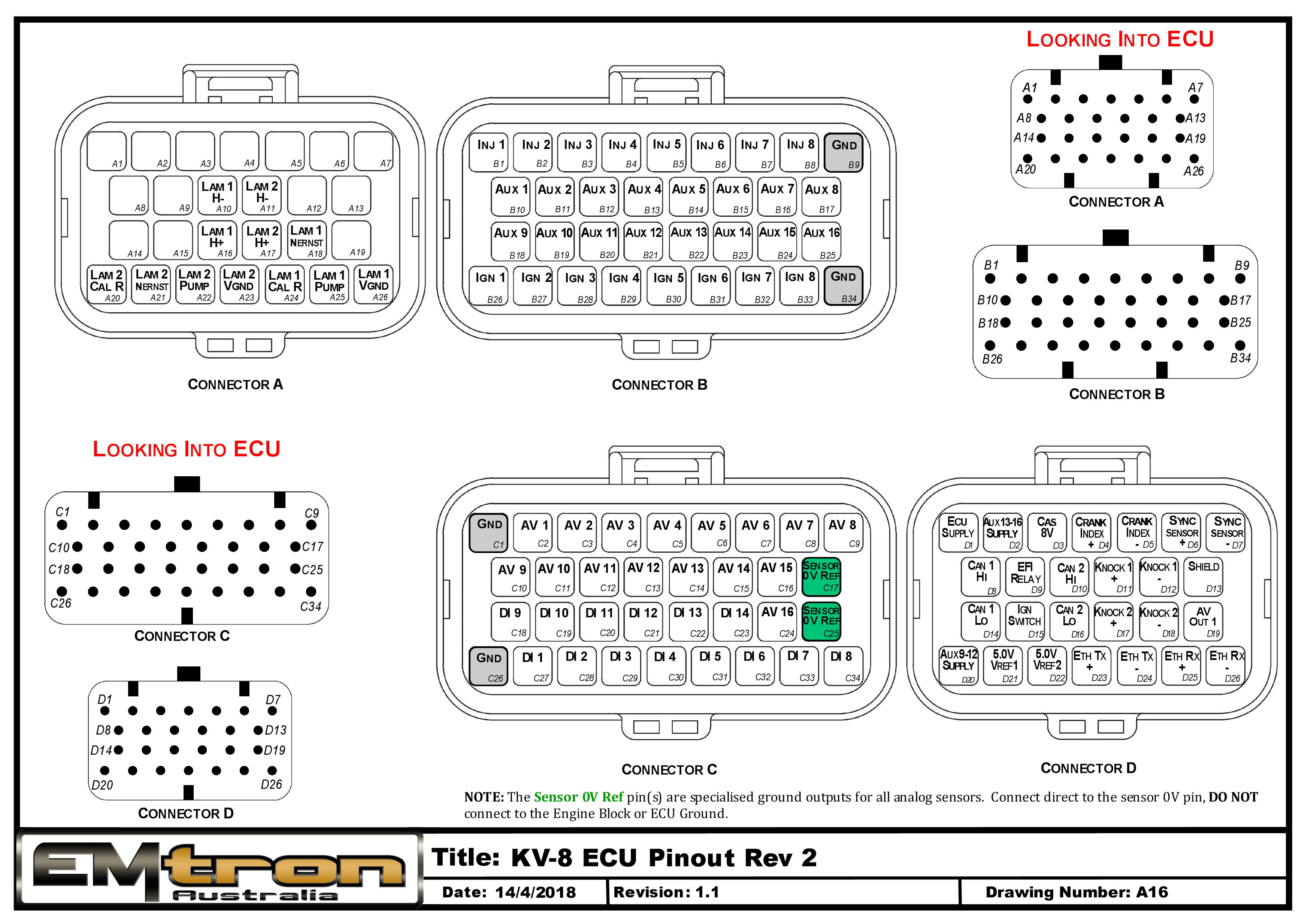
Pin Descriptions
| Connector A: Lambda (15.0A Max continuous current - wire gauge dependant) |
|---|
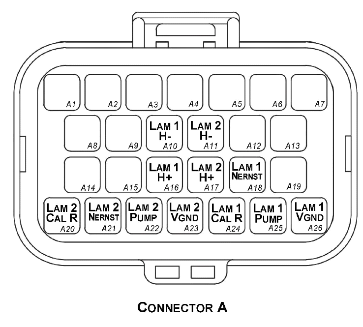
Looking into ECU connector
| Pin | Channel Name |
|---|---|
| A1 | NC |
| A2 | NC |
| A3 | NC |
| A4 | NC |
| A5 | NC |
| A6 | NC |
| A7 | NC |
| A8 | NC |
| A9 | NC |
| A10 | Lambda 1 Heater - |
| A11 | Lambda 2 Heater - |
| A12 | NC |
| A13 | NC |
| A14 | NC |
| A15 | NC |
| A16 | Lambda 1 Heater + |
| A17 | Lambda 2 Heater + |
| A18 | Lambda 1 Nernst Cell (Vs) |
| A19 | NC |
| A20 | Lambda 2 Cal Resistor (CalR) |
| A21 | Lambda 2 Nernst Cell (Vs) |
| A22 | Lambda 2 Pump Cell (Ip) |
| A23 | Lambda 2 Virtual Ground (VGnd) |
| A24 | Lambda 1 Cal Resistor (CalR) |
| A25 | Lambda 1 Pump Cell (Ip) |
| A26 | Lambda 1 Virtual Ground (VGnd) |
| Connector B: Auxiliary Outputs /Fuel/Ignition/Ground (15.0A Max continuous current - wire gauge dependant) |
|---|
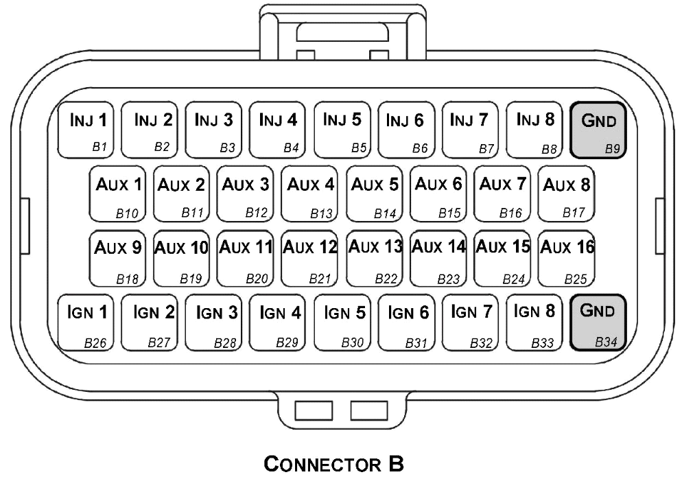
Looking into ECU connector
| Pin | Channel Name | Pin | Channel Name |
|---|---|---|---|
| B1 | Injection Channel 1 | B18 | Auxiliary Output 9 |
| B2 | Injection Channel 2 | B19 | Auxiliary Output 10 |
| B3 | Injection Channel 3 | B20 | Auxiliary Output 11 |
| B4 | Injection Channel 4 | B21 | Auxiliary Output 12 |
| B5 | Injection Channel 5 | B22 | Auxiliary Output 13 |
| B6 | Injection Channel 6 | B23 | Auxiliary Output 14 |
| B7 | Injection Channel 7 | B24 | Auxiliary Output 15 |
| B8 | Injection Channel 8 | B25 | Auxiliary Output 16 |
| B9 | ECU Ground | B26 | Ignition Channel 1 |
| B10 | Auxiliary Output 1 | B27 | Ignition Channel 2 |
| B11 | Auxiliary Output 2 | B28 | Ignition Channel 3 |
| B12 | Auxiliary Output 3 | B29 | Ignition Channel 4 |
| B13 | Auxiliary Output 4 | B30 | Ignition Channel 5 |
| B14 | Auxiliary Output 5 | B31 | Ignition Channel 6 |
| B15 | Auxiliary Output 6 | B32 | Ignition Channel 7 |
| B16 | Auxiliary Output 7 | B33 | Ignition Channel 8 |
| B17 | Auxiliary Output 8 | B34 | ECU Ground |
| Connector C: Signal (15.0A Max continuous current - wire gauge dependant) |
|---|
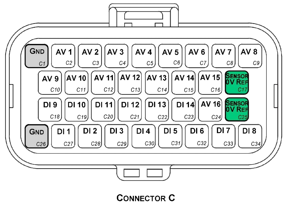
**Looking into ECU connector**
| Pin | Channel Name | Pin | Channel Name |
|---|---|---|---|
| C1 | ECU Ground | C18 | Digital Input 9 |
| C2 | Analog Input Channel 1 | C19 | Digital Input 10 |
| C3 | Analog Input Channel 2 | C20 | Digital Input 11 |
| C4 | Analog Input Channel 3 | C21 | Digital Input 12 |
| C5 | Analog Input Channel 4 | C22 | Digital Input 13 |
| C6 | Analog Input Channel 5 | C23 | Digital Input 14 |
| C7 | Analog Input Channel 6 | C24 | Analog Input Channel 16 |
| C8 | Analog Input Channel 7 | C25 | Analog Sensor 0V Reference |
| C9 | Analog Input Channel 8 | C26 | ECU Ground |
| C10 | Analog Input Channel 9 | C27 | Digital Input 1 |
| C11 | Analog Input Channel 10 | C28 | Digital Input 2 |
| C12 | Analog Input Channel 11 | C29 | Digital Input 3 |
| C13 | Analog Input Channel 12 | C30 | Digital Input 4 |
| C14 | Analog Input Channel 13 | C31 | Digital Input 5 |
| C15 | Analog Input Channel 14 | C32 | Digital Input 6 |
| C16 | Analog Input Channel 15 | C33 | Digital Input 7 |
| C17 | Analog Sensor 0V Reference | C34 | Digital Input 8 |
| Connector D: Power/Communications/Triggers/Knock (15.0A Max continuous current - wire gauge dependant) |
|---|
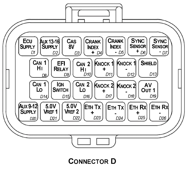
**Looking into ECU connector**
| Pin | Channel Name |
|---|---|
| D1 | ECU 14V Supply |
| D2 | Auxiliary Output 13-16 14V Supply |
| D3 | Sensor Supply 8V |
| D4 | Crank Index Sensor + |
| D5 | Crank Index Sensor - |
| D6 | Sync Sensor + |
| D7 | Sync Sensor - |
| D8 | CAN 1H |
| D9 | EFI Relay Output (Low Side 200mA) |
| D10 | CAN 2H |
| D11 | Knock 1 + |
| D12 | Knock 1 - |
| D13 | Shield (Crank/Cam/ Knock) |
| D14 | CAN 1L |
| D15 | Ignition Switch Input |
| D16 | CAN 2L |
| D17 | Knock 2 + |
| D18 | Knock 2 - |
| D19 | Analog Output (0.0 - 5.0V) |
| D20 | Auxiliary Output 9-12 14V Supply |
| D21 | Sensor Supply Vref1: 5.0V |
| D22 | Sensor Supply Vref2: 5.0V |
| D23 | Ethernet Tx + |
| D24 | Ethernet Tx - |
| D25 | Ethernet Rx + |
| D26 | Ethernet Rx - |
Important Notes
Auxiliary Output Channels 13-16
These are high current Half bridge drivers which switch either to ground or 14V i.e. they do not have a high impedance or OFF state. When the ECU is powered OFF these Auxiliary Channels by default will be switching to ground. This means:
- Solenoids or relays connected to these outputs should not use a constant or hot battery feed.
- During the ECU powerup sequence, any solenoid or relay connected to these outputs should have a managed power feed to avoid momentary switching during powerup.
Analog Sensor 0V Reference (Pin C17, C25)
These pins should be connected directly to the 0V (Ground) pin on any low current analog sensor, for example Pressure or Temperature.
- DO NOT connect the ECU pins C17, C25 directly to the Engine Block or ECU Ground. These are dedicated and specialised ground outputs for all analog channels and should be connected directly to the sensor.
- DO NOT connect frequency-based sensors to these pins; for example, an Ethanol content sensor. The sensor 0V pin should be connected to the ECU ground.
Half Bridge Driver Power Supply Inputs (Pin D20, D2)
Pin D20 is a dedicated power supply for Auxiliary Channels 9-12. Power must be supplied to this pin for these channels to operate correctly. In non-DBW (Drive by Wire) applications the ECU Supply power can be shared, assuming the wire gauge has a sufficient rating for the current demand. In DBW applications power to this pin MUST come from an ECU controlled DBW Relay.
Pin D2 is a dedicated power supply for Auxiliary Channels 13-16. Power must be supplied to this pin for these Auxiliary channels to operate correctly.
.
KV12 Pinout Rev2
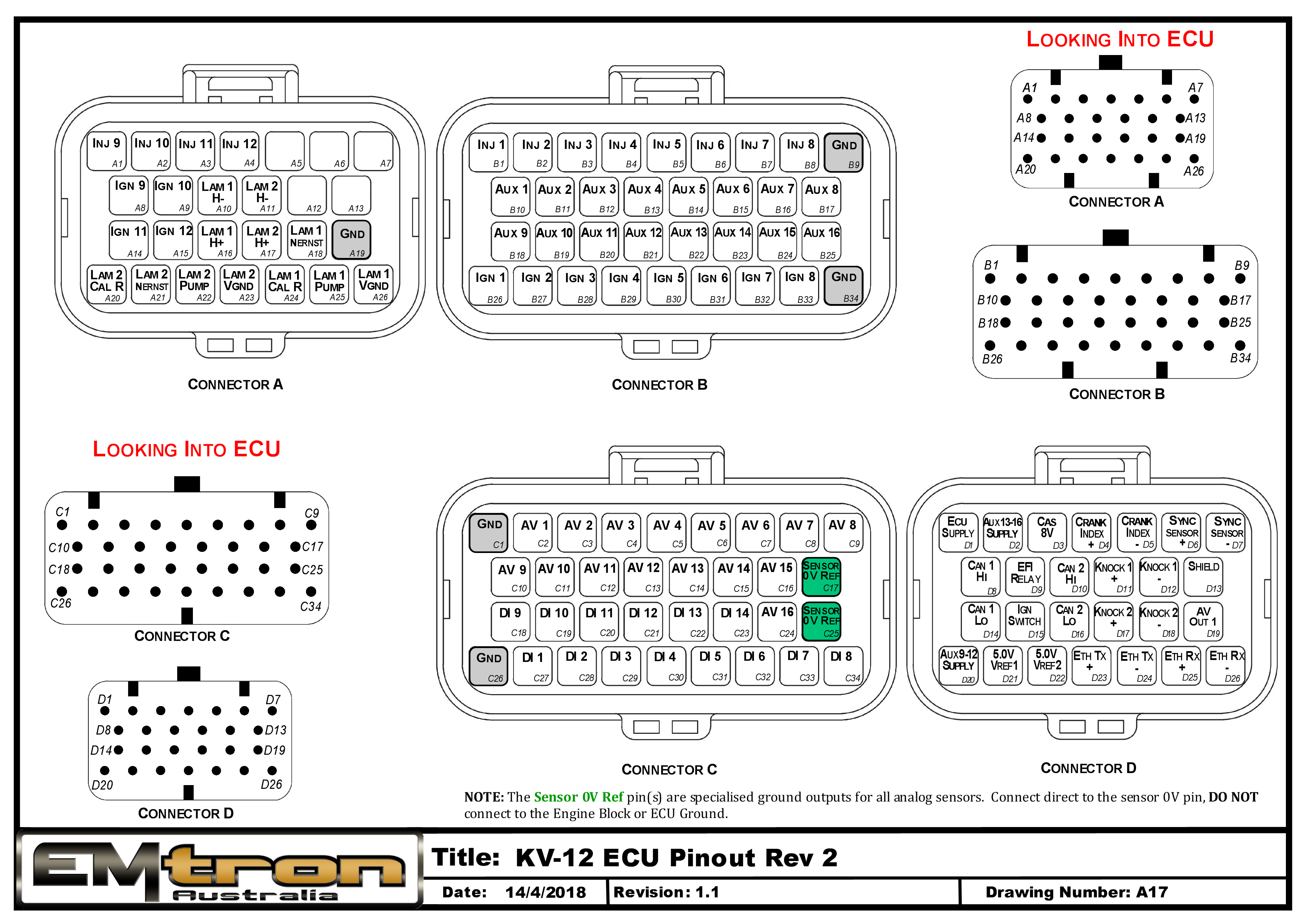
Pin Descriptions
| Connector A: Lambda/Injection/Ignition (15.0A Max continuous current - wire gauge dependant) |
|---|
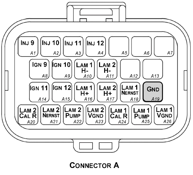
Looking into ECU connector
| Pin | Channel Name |
|---|---|
| A1 | Injection Channel 9 |
| A2 | Injection Channel 10 |
| A3 | Injection Channel 11 |
| A4 | Injection Channel 12 |
| A5 | NC |
| A6 | NC |
| A7 | NC |
| A8 | Ignition Channel 9 |
| A9 | Ignition Channel 10 |
| A10 | Lambda 1 Heater - |
| A11 | Lambda 2 Heater - |
| A12 | NC |
| A13 | NC |
| A14 | Ignition Channel 11 |
| A15 | Ignition Channel 12 |
| A16 | Lambda 1 Heater + |
| A17 | Lambda 2 Heater + |
| A18 | Lambda 1 Nernst Cell (Vs) |
| A19 | ECU Ground |
| A20 | Lambda 2 Cal Resistor (CalR) |
| A21 | Lambda 2 Nernst Cell (Vs) |
| A22 | Lambda 2 Pump Cell (Ip) |
| A23 | Lambda 2 Virtual Ground (VGnd) |
| A24 | Lambda 1 Cal Resistor (CalR) |
| A25 | Lambda 1 Pump Cell (Ip) |
| A26 | Lambda 1 Virtual Ground (VGnd) |
| Connector B: Auxiliary Outputs /Fuel/Ignition/Ground (15.0A Max continuous current - wire gauge dependant) |
|---|
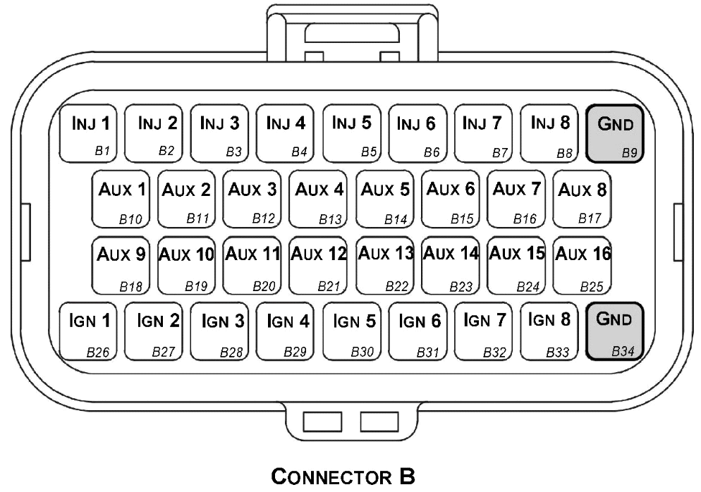
Looking into ECU connector
| Pin | Channel Name | Pin | Channel Name |
|---|---|---|---|
| B1 | Injection Channel 1 | B18 | Auxiliary Output 9 |
| B2 | Injection Channel 2 | B19 | Auxiliary Output 10 |
| B3 | Injection Channel 3 | B20 | Auxiliary Output 11 |
| B4 | Injection Channel 4 | B21 | Auxiliary Output 12 |
| B5 | Injection Channel 5 | B22 | Auxiliary Output 13 |
| B6 | Injection Channel 6 | B23 | Auxiliary Output 14 |
| B7 | Injection Channel 7 | B24 | Auxiliary Output 15 |
| B8 | Injection Channel 8 | B25 | Auxiliary Output 16 |
| B9 | ECU Ground | B26 | Ignition Channel 1 |
| B10 | Auxiliary Output 1 | B27 | Ignition Channel 2 |
| B11 | Auxiliary Output 2 | B28 | Ignition Channel 3 |
| B12 | Auxiliary Output 3 | B29 | Ignition Channel 4 |
| B13 | Auxiliary Output 4 | B30 | Ignition Channel 5 |
| B14 | Auxiliary Output 5 | B31 | Ignition Channel 6 |
| B15 | Auxiliary Output 6 | B32 | Ignition Channel 7 |
| B16 | Auxiliary Output 7 | B33 | Ignition Channel 8 |
| B17 | Auxiliary Output 8 | B34 | ECU Ground |
| Connector C: Signal (15.0A Max continuous current - wire gauge dependant) |
|---|
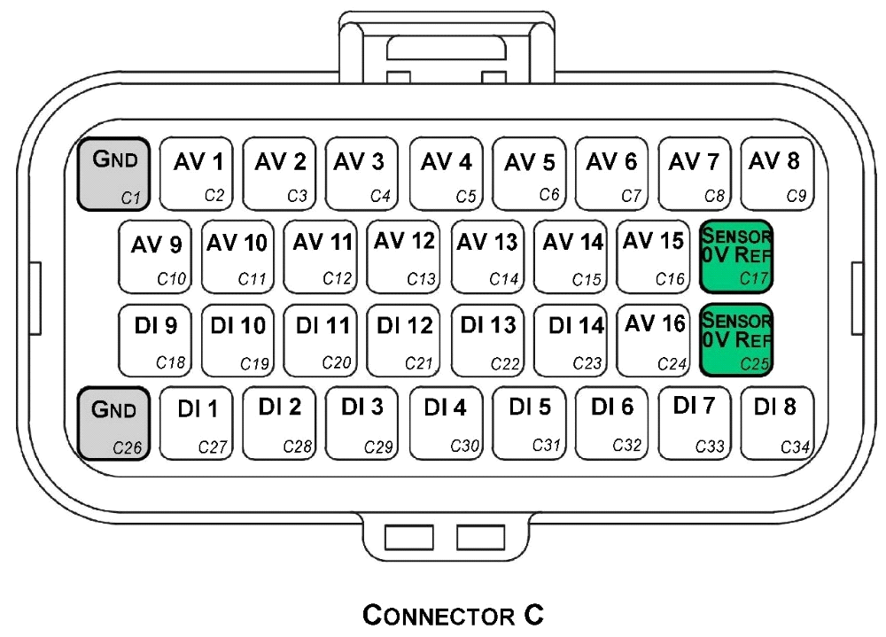
Looking into ECU connector
| Pin | Channel Name | Pin | Channel Name |
|---|---|---|---|
| C1 | ECU Ground | C18 | Digital Input 9 |
| C2 | Analog Input Channel 1 | C19 | Digital Input 10 |
| C3 | Analog Input Channel 2 | C20 | Digital Input 11 |
| C4 | Analog Input Channel 3 | C21 | Digital Input 12 |
| C5 | Analog Input Channel 4 | C22 | Digital Input 13 |
| C6 | Analog Input Channel 5 | C23 | Digital Input 14 |
| C7 | Analog Input Channel 6 | C24 | Analog Input Channel 16 |
| C8 | Analog Input Channel 7 | C25 | Analog Sensor 0V Reference |
| C9 | Analog Input Channel 8 | C26 | ECU Ground |
| C10 | Analog Input Channel 9 | C27 | Digital Input 1 |
| C11 | Analog Input Channel 10 | C28 | Digital Input 2 |
| C12 | Analog Input Channel 11 | C29 | Digital Input 3 |
| C13 | Analog Input Channel 12 | C30 | Digital Input 4 |
| C14 | Analog Input Channel 13 | C31 | Digital Input 5 |
| C15 | Analog Input Channel 14 | C32 | Digital Input 6 |
| C16 | Analog Input Channel 15 | C33 | Digital Input 7 |
| C17 | Analog Sensor 0V Reference | C34 | Digital Input 8 |
| Connector D: Power/Communications/Triggers/Knock (15.0A Max continuous current - wire gauge dependant) |
|---|
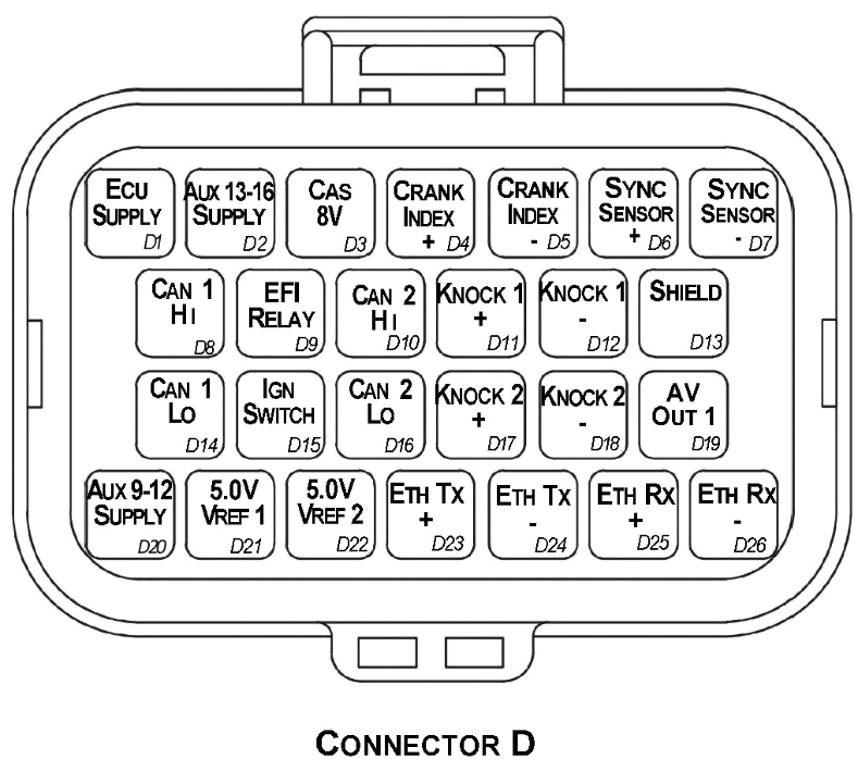
Looking into ECU connector
| Pin | Channel Name |
|---|---|
| D1 | ECU 14V Supply |
| D2 | Auxiliary Output 13-16 14V Supply |
| D3 | Sensor Supply 8V |
| D4 | Crank Index Sensor + |
| D5 | Crank Index Sensor - |
| D6 | Sync Sensor + |
| D7 | Sync Sensor - |
| D8 | CAN 1H |
| D9 | EFI Relay Output (Low Side 200mA) |
| D10 | CAN 2H |
| D11 | Knock 1 + |
| D12 | Knock 1 - |
| D13 | Shield (Crank/Cam/ Knock) |
| D14 | CAN 1L |
| D15 | Ignition Switch Input |
| D16 | CAN 2L |
| D17 | Knock 2 + |
| D18 | Knock 2 - |
| D19 | Analog Output (0.0 - 5.0V) |
| D20 | Auxiliary Output 9-12 14V Supply |
| D21 | Sensor Supply Vref1: 5.0V |
| D22 | Sensor Supply Vref2: 5.0V |
| D23 | Ethernet Tx + |
| D24 | Ethernet Tx - |
| D25 | Ethernet Rx + |
| D26 | Ethernet Rx - |
Important Notes
Auxiliary Output Channels 13-16
These are high current Half bridge drivers which switch either to ground or 14V i.e. they do not have a high impedance or OFF state. When the ECU is powered OFF these Auxiliary Channels by default will be switching to ground. This means:
- Solenoids or relays connected to these outputs should not use a constant or hot battery feed.
- During the ECU powerup sequence, any solenoid or relay connected to these outputs should have a managed power feed to avoid momentary switching during powerup.
Analog Sensor 0V Reference (Pin C17, C25)
These pins should be connected directly to the 0V (Ground) pin on any low current analog sensor, for example Pressure or Temperature.
- DO NOT connect the ECU pins C17, C25 directly to the Engine Block or ECU Ground. These are dedicated and specialised ground outputs for all analog channels and should be connected directly to the sensor.
- DO NOT connect frequency-based sensors to these pins; for example, an Ethanol content sensor. The sensor 0V pin should be connected to the ECU ground.
Half Bridge Driver Power Supply Inputs (Pin D20, D2)
Pin D20 is a dedicated power supply for Auxiliary Channels 9-12. Power must be supplied to this pin for these channels to operate correctly. In non-DBW (Drive by Wire) applications the ECU Supply power can be shared, assuming the wire gauge has a sufficient rating for the current demand. In DBW applications power to this pin MUST come from an ECU controlled DBW Relay.
Pin D2 is a dedicated power supply for Auxiliary Channels 13-16. Power must be supplied to this pin for these Auxiliary channels to operate correctly.
KV16 Pinout Rev2
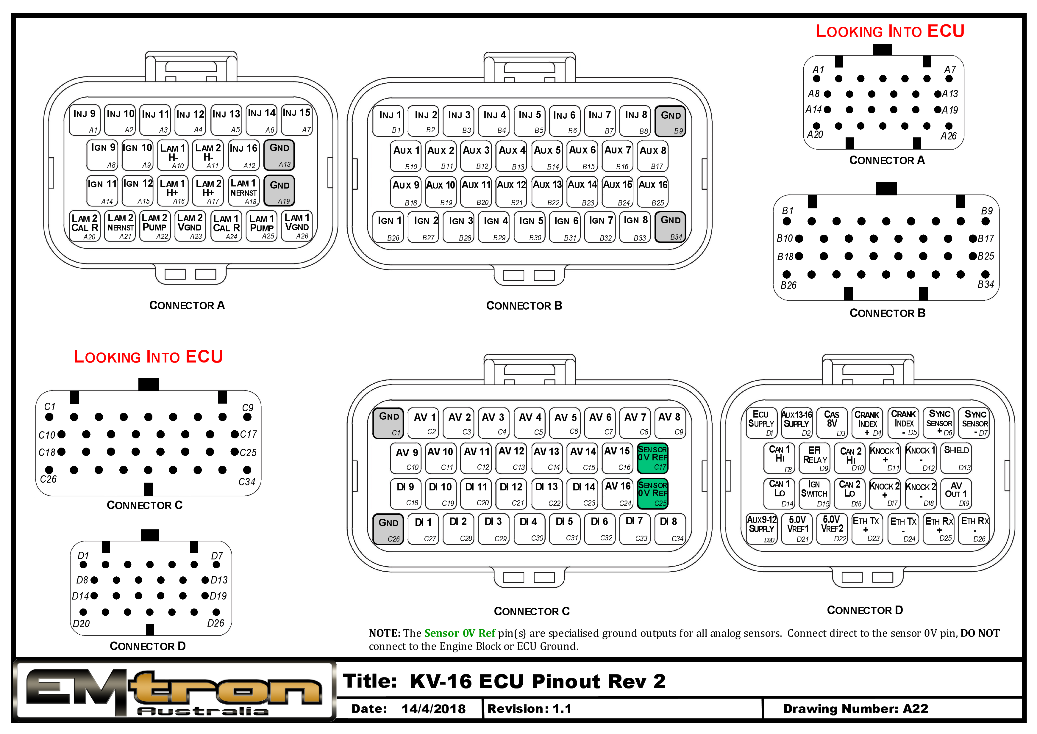
Pin Descriptions
| Connector A: Lambda/Injection/Ignition (15.0A Max continuous current - wire gauge dependant) |
|---|
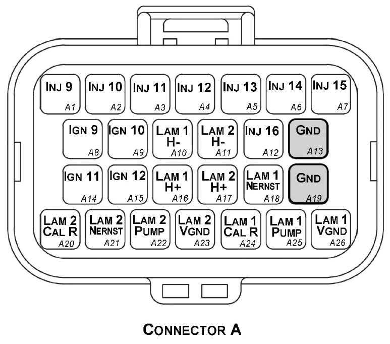
Looking into ECU connector
| Pin | Channel Name |
|---|---|
| A1 | Injection Channel 9 |
| A2 | Injection Channel 10 |
| A3 | Injection Channel 11 |
| A4 | Injection Channel 12 |
| A5 | Injection Channel 13 |
| A6 | Injection Channel 14 |
| A7 | Injection Channel 15 |
| A8 | Ignition Channel 9 |
| A9 | Ignition Channel 10 |
| A10 | Lambda 1 Heater - |
| A11 | Lambda 2 Heater - |
| A12 | Injection Channel 16 |
| A13 | ECU Ground |
| A14 | Ignition Channel 11 |
| A15 | Ignition Channel 12 |
| A16 | Lambda 1 Heater + |
| A17 | Lambda 2 Heater + |
| A18 | Lambda 1 Nernst Cell (Vs) |
| A19 | ECU Ground |
| A20 | Lambda 2 Cal Resistor (CalR) |
| A21 | Lambda 2 Nernst Cell (Vs) |
| A22 | Lambda 2 Pump Cell (Ip) |
| A23 | Lambda 2 Virtual Ground (VGnd) |
| A24 | Lambda 1 Cal Resistor (CalR) |
| A25 | Lambda 1 Pump Cell (Ip) |
| A26 | Lambda 1 Virtual Ground (VGnd) |
| Connector B: Auxiliary Outputs /Fuel/Ignition/Ground (15.0A Max continuous current - wire gauge dependant) |
|---|
Looking into ECU connector
| Pin | Channel Name | Pin | Channel Name |
|---|---|---|---|
| B1 | Injection Channel 1 | B18 | Auxiliary Output 9 |
| B2 | Injection Channel 2 | B19 | Auxiliary Output 10 |
| B3 | Injection Channel 3 | B20 | Auxiliary Output 11 |
| B4 | Injection Channel 4 | B21 | Auxiliary Output 12 |
| B5 | Injection Channel 5 | B22 | Auxiliary Output 13 |
| B6 | Injection Channel 6 | B23 | Auxiliary Output 14 |
| B7 | Injection Channel 7 | B24 | Auxiliary Output 15 |
| B8 | Injection Channel 8 | B25 | Auxiliary Output 16 |
| B9 | ECU Ground | B26 | Ignition Channel 1 |
| B10 | Auxiliary Output 1 | B27 | Ignition Channel 2 |
| B11 | Auxiliary Output 2 | B28 | Ignition Channel 3 |
| B12 | Auxiliary Output 3 | B29 | Ignition Channel 4 |
| B13 | Auxiliary Output 4 | B30 | Ignition Channel 5 |
| B14 | Auxiliary Output 5 | B31 | Ignition Channel 6 |
| B15 | Auxiliary Output 6 | B32 | Ignition Channel 7 |
| B16 | Auxiliary Output 7 | B33 | Ignition Channel 8 |
| B17 | Auxiliary Output 8 | B34 | ECU Ground |
| Connector C: Signal (15.0A Max continuous current - wire gauge dependant) |
|---|
Looking into ECU connector
| Pin | Channel Name | Pin | Channel Name |
|---|---|---|---|
| C1 | ECU Ground | C18 | Digital Input 9 |
| C2 | Analog Input Channel 1 | C19 | Digital Input 10 |
| C3 | Analog Input Channel 2 | C20 | Digital Input 11 |
| C4 | Analog Input Channel 3 | C21 | Digital Input 12 |
| C5 | Analog Input Channel 4 | C22 | Digital Input 13 |
| C6 | Analog Input Channel 5 | C23 | Digital Input 14 |
| C7 | Analog Input Channel 6 | C24 | Analog Input Channel 16 |
| C8 | Analog Input Channel 7 | C25 | Analog Sensor 0V Reference |
| C9 | Analog Input Channel 8 | C26 | ECU Ground |
| C10 | Analog Input Channel 9 | C27 | Digital Input 1 |
| C11 | Analog Input Channel 10 | C28 | Digital Input 2 |
| C12 | Analog Input Channel 11 | C29 | Digital Input 3 |
| C13 | Analog Input Channel 12 | C30 | Digital Input 4 |
| C14 | Analog Input Channel 13 | C31 | Digital Input 5 |
| C15 | Analog Input Channel 14 | C32 | Digital Input 6 |
| C16 | Analog Input Channel 15 | C33 | Digital Input 7 |
| C17 | Analog Sensor 0V Reference | C34 | Digital Input 8 |
| Connector D: Power/Communications/Triggers/Knock (15.0A Max continuous current - wire gauge dependant) |
|---|
Looking into ECU connector
| Pin | Channel Name |
|---|---|
| D1 | ECU 14V Supply |
| D2 | Auxiliary Output 13-16 14V Supply |
| D3 | Sensor Supply 8V |
| D4 | Crank Index Sensor + |
| D5 | Crank Index Sensor - |
| D6 | Sync Sensor + |
| D7 | Sync Sensor - |
| D8 | CAN 1H |
| D9 | EFI Relay Output (Low Side 200mA) |
| D10 | CAN 2H |
| D11 | Knock 1 + |
| D12 | Knock 1 - |
| D13 | Shield (Crank/Cam/ Knock) |
| D14 | CAN 1L |
| D15 | Ignition Switch Input |
| D16 | CAN 2L |
| D17 | Knock 2 + |
| D18 | Knock 2 - |
| D19 | Analog Output (0.0 - 5.0V) |
| D20 | Auxiliary Output 9-12 14V Supply |
| D21 | Sensor Supply Vref1: 5.0V |
| D22 | Sensor Supply Vref2: 5.0V |
| D23 | Ethernet Tx + |
| D24 | Ethernet Tx - |
| D25 | Ethernet Rx + |
| D26 | Ethernet Rx - |
Important Notes
Auxiliary Output Channels 13-16
These are high current Half bridge drivers which switch either to ground or 14V i.e. they do not have a high impedance or OFF state. When the ECU is powered OFF these Auxiliary Channels by default will be switching to ground. This means:
- Solenoids or relays connected to these outputs should not use a constant or hot battery feed.
- During the ECU powerup sequence, any solenoid or relay connected to these outputs should have a managed power feed to avoid momentary switching during powerup.
Analog Sensor 0V Reference (Pin C17, C25)
These pins should be connected directly to the 0V (Ground) pin on any low current analog sensor, for example Pressure or Temperature.
- DO NOT connect the ECU pins C17, C25 directly to the Engine Block or ECU Ground. These are dedicated and specialised ground outputs for all analog channels and should be connected directly to the sensor.
- DO NOT connect frequency-based sensors to these pins; for example, an Ethanol content sensor. The sensor 0V pin should be connected to the ECU ground.
Half Bridge Driver Power Supply Inputs (Pin D20, D2)
Pin D20 is a dedicated power supply for Auxiliary Channels 9-12. Power must be supplied to this pin for these channels to operate correctly. In non-DBW (Drive by Wire) applications the ECU Supply power can be shared, assuming the wire gauge has a sufficient rating for the current demand. In DBW applications power to this pin MUST come from an ECU controlled DBW Relay.
Pin D2 is a dedicated power supply for Auxiliary Channels 13-16. Power must be supplied to this pin for these Auxiliary channels to operate correctly.
KV16M Pinout
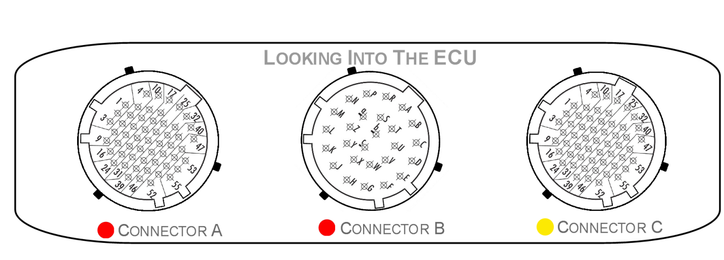
| Mating Connectors Loom Side (Deutsch Autosport AS Series; S = Socket#8202;) |
|---|
| Mating connector A AS616-35SN (Red) |
| Mating connector B AS616-26SN (Red) |
| Mating connector C AS616-35SA (Yellow) |
| Connector A: Injection/Ignition/Digital Inputs. (5.0A continuous current. Shell size 16, 55 Pin. 22 AWG) |
|---|
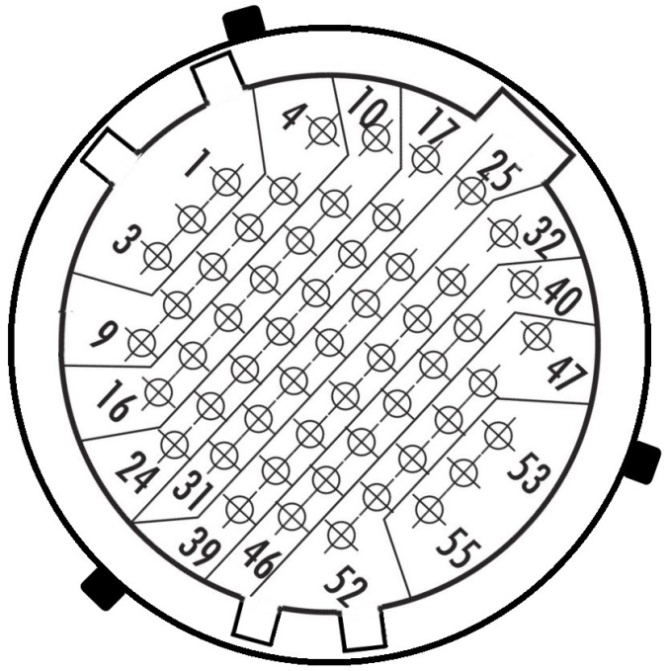
**Looking into ECU Connector**
| Pin | Channel Name | Pin | Channel Name |
|---|---|---|---|
| 1 | Injection Channel 1 | 29 | Lambda 2 Heater + |
| 2 | Injection Channel 2 | 30 | Lambda 2 Heater - |
| 3 | Injection Channel 3 | 31 | Digital Input Ground Out |
| 4 | Injection Channel 4 | 32 | Ignition Channel 1 |
| 5 | Injection Channel 5 | 33 | Ignition Channel 2 |
| 6 | Injection Channel 6 | 34 | Ignition Channel 3 |
| 7 | Injection Channel 7 | 35 | Ignition Channel 4 |
| 8 | Injection Channel 8 | 36 | Ignition Channel 5 |
| 9 | Injection Channel 9 | 37 | Ignition Channel 6 |
| 10 | Injection Channel 10 | 38 | Ignition Channel 7 |
| 11 | Injection Channel 11 | 39 | Ignition Channel 8 |
| 12 | Injection Channel 12 | 40 | Ignition Channel 9 |
| 13 | Injection Channel 13 | 41 | Ignition Channel 10 |
| 14 | Injection Channel 14 | 42 | Ignition Channel 11 |
| 15 | Injection Channel 15 | 43 | Ignition Channel 12 |
| 16 | Injection Channel 16 | 44 | Digital Input 3 |
| 17 | Lambda 1 Nernst Cell (Vs) | 45 | Digital Input 2 |
| 18 | Lambda 1 Cal Resistor (CalR) | 46 | Digital Input 1 |
| 19 | Lambda 1 Pump Cell (Ip) | 47 | Digital Input 9 |
| 20 | Lambda 1 Virtual Ground (VGnd) | 48 | Digital Input 8 |
| 21 | Lambda 1 Heater + | 49 | Digital Input 7 |
| 22 | Lambda 1 Heater - | 50 | Digital Input 6 |
| 23 | Digital Input 13 | 51 | Digital Input 5 |
| 24 | Digital Input 14 | 52 | Digital Input 4 |
| 25 | Lambda 2 Pump Cell (Ip) | 53 | Digital Input 10 |
| 26 | Lambda 2 Virtual Ground (VGnd) | 54 | Digital Input 11 |
| 27 | Lambda 2 Nernst Cell (Vs) | 55 | Digital Input 12 |
| 28 | Lambda 2 Cal Resistor (CalR) |
| Connector B: Power/Ground/Auxiliary Outputs (7.5A continuous current. Shell size 16, 26 Pin. 20 AWG) |
|---|
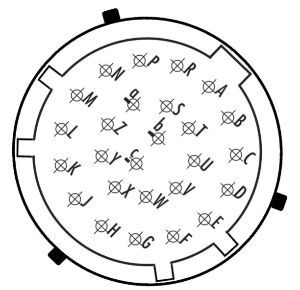
Looking into ECU Connector
| Pin | Channel Name |
|---|---|
| A | ECU 14V Supply |
| B | ECU 14V Supply |
| C | ECU 14V Supply |
| D | ECU Ground |
| E | ECU Ground |
| F | Auxiliary Output 16 |
| G | Auxiliary Output 15 |
| H | Auxiliary Output 14 |
| J | Auxiliary Output 12 |
| K | Auxiliary Output 10 |
| L | Auxiliary Output 8 |
| M | Auxiliary Output 7 |
| N | Auxiliary Output 5 |
| P | Auxiliary Output 3 |
| R | Auxiliary Output 1 |
| S | Auxiliary Output 2 |
| T | ECU 14V Supply |
| U | ECU Ground |
| V | ECU Ground |
| W | Auxiliary Output 13 |
| X | Auxiliary Output 11 |
| Y | Auxiliary Output 9 |
| Z | Auxiliary Output 6 |
| a | Auxiliary Output 4 |
| b | ECU Ground |
| c | ECU Ground |
| Connector: C Signal. (5.0A continuous current. Shell size 16, 55 Pin. 22 AWG) |
|---|
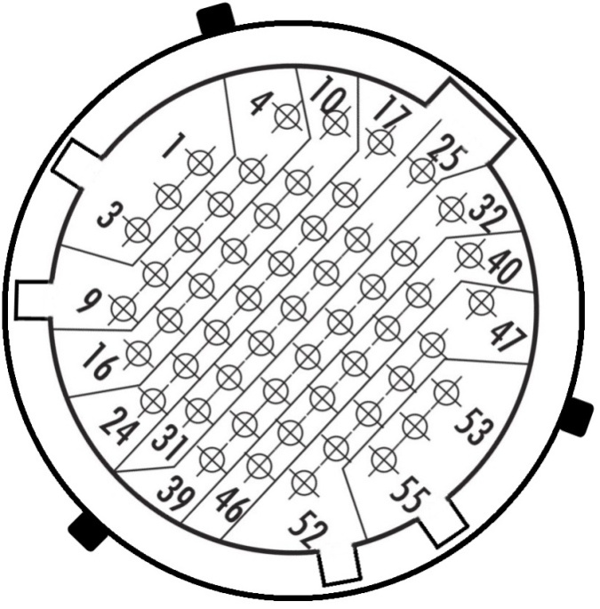
**Looking into ECU Connector**
| Pin | Channel Name | Pin | Channel Name |
|---|---|---|---|
| 1 | Analog Input Channel 1 | 29 | Analog Sensor 0V Reference |
| 2 | Analog Input Channel 2 | 30 | Analog Sensor 0V Reference |
| 3 | Analog Input Channel 3 | 31 | Analog Sensor 0V Reference |
| 4 | Analog Input Channel 4 | 32 | Knock 2 + |
| 5 | Analog Input Channel 5 | 33 | Analog Out |
| 6 | Analog Input Channel 6 | 34 | CAN 2L |
| 7 | Analog Input Channel 7 | 35 | CAN 2H |
| 8 | Analog Input Channel 8 | 36 | CAN 1L |
| 9 | Analog Input Channel 9 | 37 | CAN 1H |
| 10 | Analog Input Channel 10 | 38 | Sensor Supply Vref2: 5.0V |
| 11 | Analog Input Channel 11 | 39 | Sensor Supply Vref2: 5.0V |
| 12 | Analog Input Channel 12 | 40 | Knock 1 - |
| 13 | Analog Input Channel 13 | 41 | Sync Sensor - |
| 14 | Analog Input Channel 14 | 42 | Sync Sensor + |
| 15 | Analog Input Channel 15 | 43 | Crank Index Sensor - |
| 16 | Analog Input Channel 16 | 44 | Crank Index Sensor + |
| 17 | Analog Input Channel 17 | 45 | Sensor Supply Vref1: 5.0V |
| 18 | Analog Input Channel 18 | 46 | Sensor Supply Vref1: 5.0V |
| 19 | Analog Input Channel 19 | 47 | Knock 1 + |
| 20 | Analog Input Channel 20 | 48 | Ethernet Tx + |
| 21 | Analog Input Channel 21 | 49 | Ethernet Tx - |
| 22 | Analog Input Channel 22 | 50 | Ethernet Rx + |
| 23 | Analog Input Channel 23 | 51 | Ethernet Rx - |
| 24 | Analog Input Channel 24 | 52 | Sensor Supply 8V |
| 25 | Knock 2 - | 53 | Constant 14V Supply(Backup) |
| 26 | SHIELD (Crank/Cam/ Knock) | 54 | Sensor Supply Vref3: 5.0V |
| 27 | SHIELD (Crank/Cam/ Knock) | 55 | Sensor Supply Vref3: 5.0V |
| 28 | Analog Sensor 0V Reference |
Important Notes
Auxiliary Output Channels 13-16
These are high current Half bridge drivers which switch either to ground or 14V i.e. they do not have a high impedance or OFF state. When the ECU is powered OFF these Auxiliary Channels by default will be switching to ground. This means:
- Solenoids or relays connected to these outputs should not use a constant or hot battery feed.
- During the ECU powerup sequence, any solenoid or relay connected to these outputs should have a managed power feed to avoid momentary switching during powerup.
Constant 14V Supply/Backup (Pin C53)
This pin has two features:
1) Flywheeling for Auxiliary Channels 1-8. Any Inductive energy will be sent to the “Constant 14V Supply” pin. To minimise any EMI and allow solenoid current recirculation to operate correctly this pin should be connected to a constant power supply. If this pin is left unconnected the back EMF will be clamped at 45V.
2) Internal ECU EFI Relay function. When power is removed from pins " ECU 14V Supply" the ECU automatically switches to the “Constant 14V Supply” to keep the ECU powered. This will allow the ECU to complete critical tasks before shutting itself down (for example, DBW Self calibration and ECU Logging data storage).
To enable this function, set the EFI Relay Control Channel to “Internal EFI Relay Ctrl”
NOTE: With a Constant 14V supply wired, the ECU draws no additional current when OFF.
Analog Sensor 0V Reference (Pin C28, C29, C30, C31)
As the name indicates these should be connected directly to the 0V (Ground) pin on any low current analog sensor, for example Pressure or Temperature.
- DO NOT connect these pins directly to the Engine Block or ECU Ground. These are dedicated and specialised ground outputs for all analog channels and should be connected directly to the sensor.
- DO NOT connect frequency-based sensors to this ground; for example, an Ethanol content sensor. Use either the Digital Input Ground Out pin (A31) or the main ECU ground.
KV8 Pinout Rev1
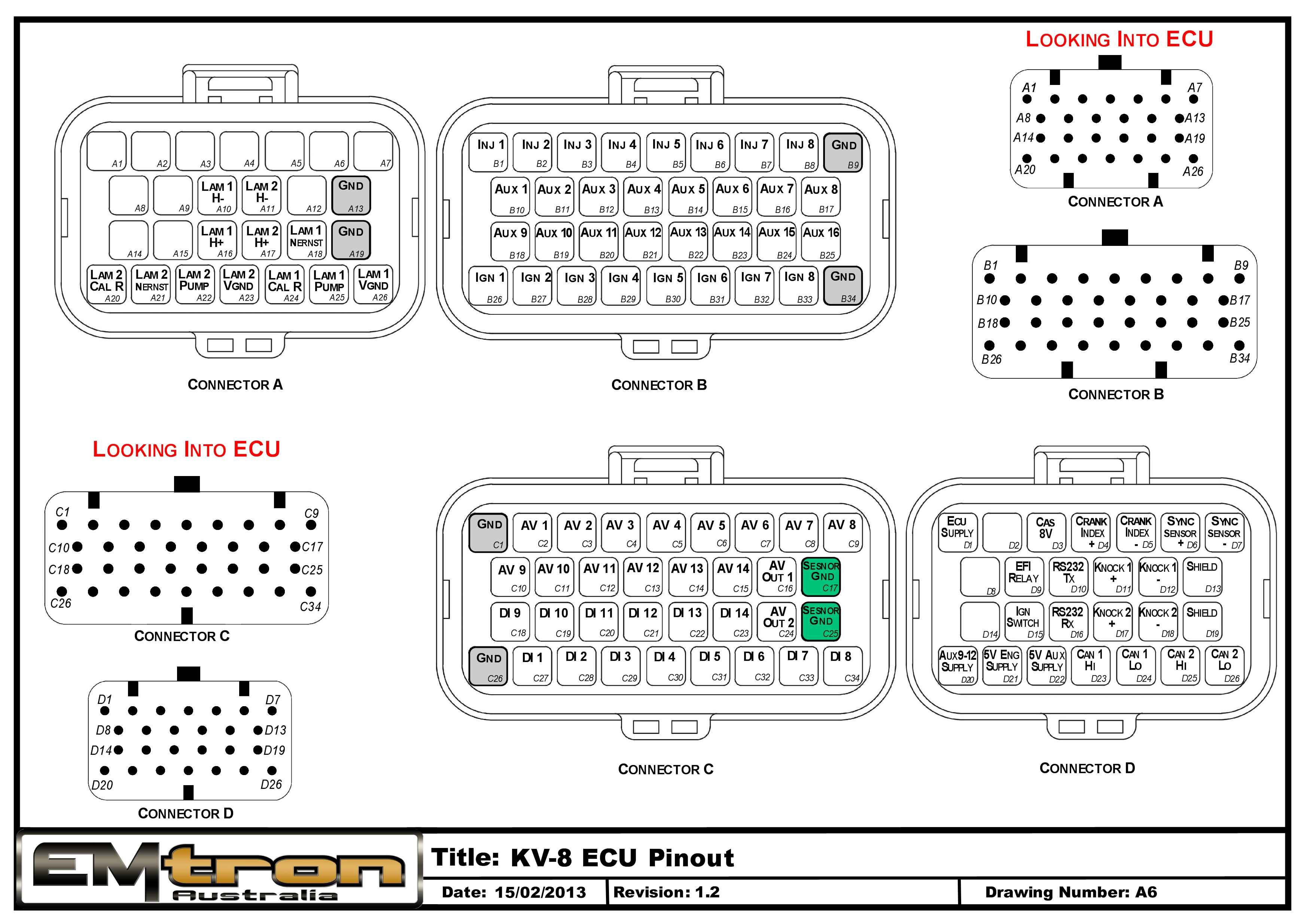
KV12 Pinout Rev1
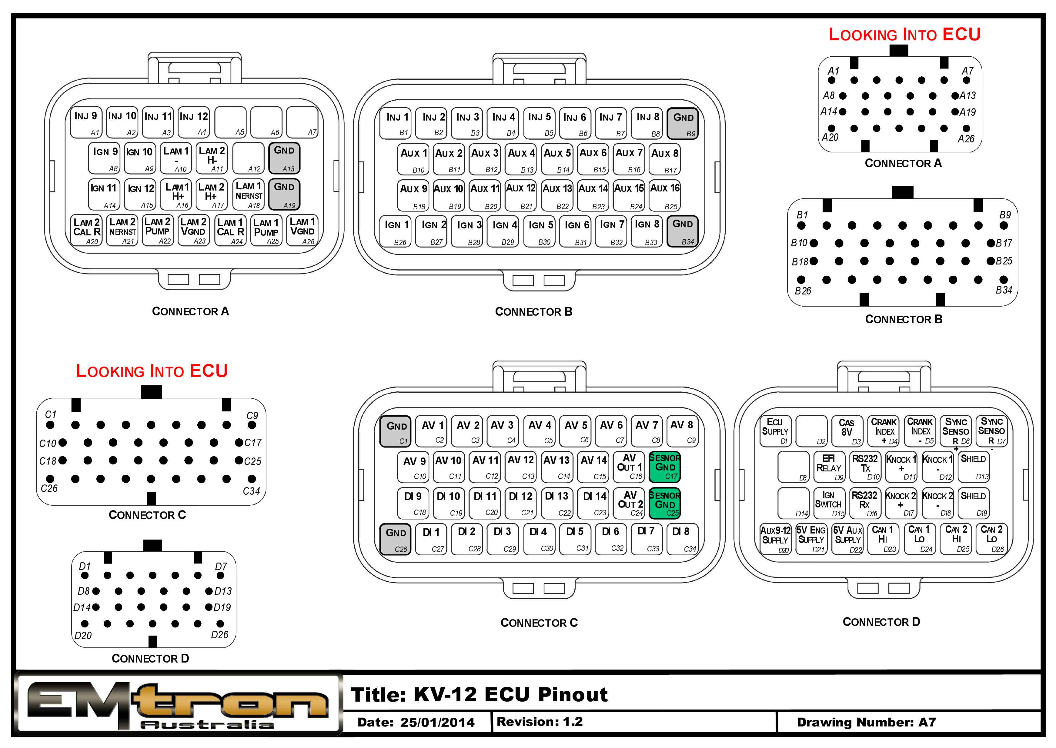
KV16 Pinout Rev1
KV Series Wiring Harness Specification
1.0 Introduction
This document contains the specification for the Emtron KV Series wiring harness.
- Loom Length = 2.5 meters
- Wire Type = AVSS
NoteNOTE Any unused pins or not-fitted wires MUST have blanking bungs fitted to the connector to keep the plug rated at its IP standard.
2.0 Connector A
| Property | Value |
|---|---|
| Name | Superseal |
| Manufacturer | TE |
| Description | 26 Way / Key 2 |
| Part Number | 3-1437290-8 |
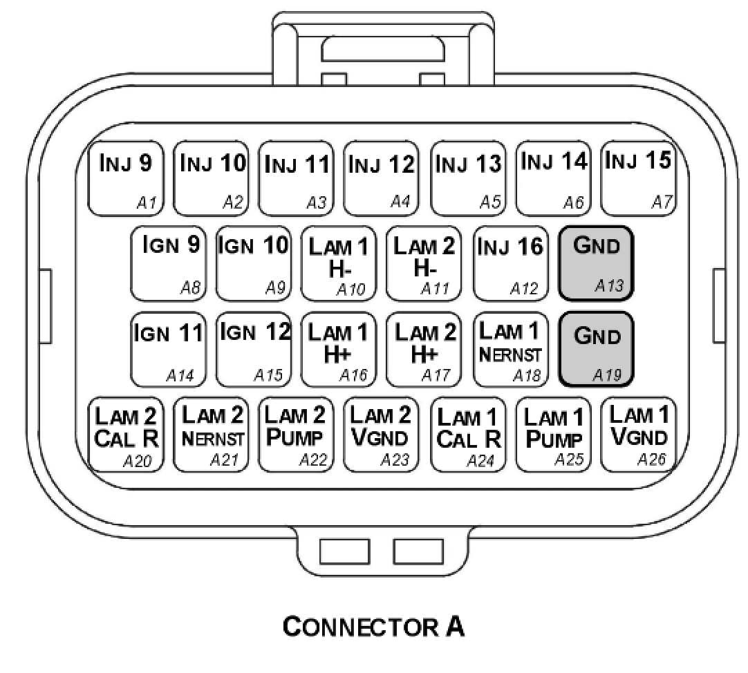
Connector A — TE Superseal 26 Way / Key 2.
2.1 Connector A Wire Colours
| Pin Name | Pin | Description | Colour | Wire Size (sq mm) |
|---|---|---|---|---|
| INJ 9 | A1 | Injector Channel 9 | Blue | 0.50 |
| INJ 10 | A2 | Injector Channel 10 | Blue | 0.50 |
| INJ 11 | A3 | Injector Channel 11 | Blue | 0.50 |
| INJ 12 | A4 | Injector Channel 12 | Blue | 0.50 |
| INJ 13 | A5 | Injector Channel 13 | Blue | 0.50 |
| INJ 14 | A6 | Injector Channel 14 | Blue | 0.50 |
| INJ 15 | A7 | Injector Channel 15 | Blue | 0.50 |
| IGN 9 | A8 | Ignition Channel 9 | Yellow | 0.50 |
| IGN 10 | A9 | Ignition Channel 10 | Yellow | 0.50 |
| Lam 1 H- | A10 | Lambda 1 Heater - | Green | 0.50 |
| Lam 2 H- | A11 | Lambda 2 Heater - | Green | 0.50 |
| INJ 16 | A12 | Injector Channel 16 | Blue | 0.50 |
| GND | A13 | Power Ground | Black | 0.85 |
| IGN 11 | A14 | Ignition Channel 11 | Yellow | 0.50 |
| IGN 12 | A15 | Ignition Channel 12 | Yellow | 0.50 |
| Lam 1 H+ | A16 | Lambda 1 Heater 12V | Green | 0.50 |
| Lam 2 H+ | A17 | Lambda 2 Heater 12V | Green | 0.50 |
| LAM 1 Nernst | A18 | Lambda 1 Nernst Cell | Green | 0.50 |
| GND | A19 | Power Ground | Black | 0.85 |
| LAM 2 Cal R | A20 | Lambda 2 Cal Res. | Green | 0.50 |
| LAM 2 Nernst | A21 | Lambda 2 Nernst Cell | Green | 0.50 |
| LAM 2 Pump | A22 | Lambda 2 Pump Current | Green | 0.50 |
| LAM 2 VGND | A23 | Lambda 2 Virtual Gnd | Green | 0.50 |
| LAM 1 Cal R | A24 | Lambda 1 Cal Res. | Green | 0.50 |
| LAM 1 Pump | A25 | Lambda 1 Pump Current | Green | 0.50 |
| LAM 1 VGND | A26 | Lambda 1 Virtual Gnd | Green | 0.50 |
3.0 Connector B
| Property | Value |
|---|---|
| Name | Superseal |
| Manufacturer | TE |
| Description | 34 Way / Key 2 |
| Part Number | 4-1437290-1 |
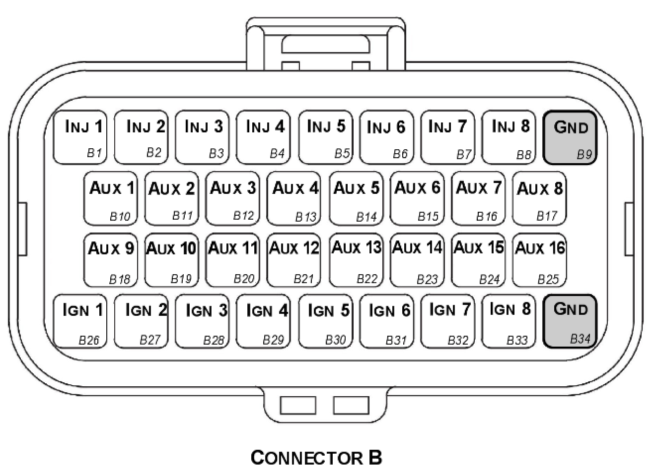
Connector B — TE Superseal 34 Way / Key 2.
3.1 Connector B Wire Colours
| Pin Name | Pin | Description | Colour | Wire Size (sq mm) |
|---|---|---|---|---|
| INJ 1 | B1 | Injector Channel 1 | Blue | 0.50 |
| INJ 2 | B2 | Injector Channel 2 | Blue | 0.50 |
| INJ 3 | B3 | Injector Channel 3 | Blue | 0.50 |
| INJ 4 | B4 | Injector Channel 4 | Blue | 0.50 |
| INJ 5 | B5 | Injector Channel 5 | Blue | 0.50 |
| INJ 6 | B6 | Injector Channel 6 | Blue | 0.50 |
| INJ 7 | B7 | Injector Channel 7 | Blue | 0.50 |
| INJ 8 | B8 | Injector Channel 8 | Blue | 0.50 |
| GND | B9 | Power Ground | Black | 0.85 |
| AUX 1 | B10 | Auxiliary Channel 1 | Grey | 0.50 |
| AUX 2 | B11 | Auxiliary Channel 2 | Grey | 0.50 |
| AUX 3 | B12 | Auxiliary Channel 3 | Grey | 0.50 |
| AUX 4 | B13 | Auxiliary Channel 4 | Grey | 0.50 |
| AUX 5 | B14 | Auxiliary Channel 5 | Grey | 0.50 |
| AUX 6 | B15 | Auxiliary Channel 6 | Grey | 0.50 |
| AUX 7 | B16 | Auxiliary Channel 7 | Grey | 0.50 |
| AUX 8 | B17 | Auxiliary Channel 8 | Grey | 0.50 |
| AUX 9 | B18 | Auxiliary Channel 9 | Grey | 0.50 |
| AUX 10 | B19 | Auxiliary Channel 10 | Grey | 0.50 |
| AUX 11 | B20 | Auxiliary Channel 11 | Grey | 0.50 |
| AUX 12 | B21 | Auxiliary Channel 12 | Grey | 0.50 |
| AUX 13 | B22 | Auxiliary Channel 13 | Grey | 0.50 |
| AUX 14 | B23 | Auxiliary Channel 14 | Grey | 0.50 |
| AUX 15 | B24 | Auxiliary Channel 15 | Grey | 0.50 |
| AUX 16 | B25 | Auxiliary Channel 16 | Grey | 0.50 |
| IGN 1 | B26 | Ignition Channel 1 | Yellow | 0.50 |
| IGN 2 | B27 | Ignition Channel 2 | Yellow | 0.50 |
| IGN 3 | B28 | Ignition Channel 3 | Yellow | 0.50 |
| IGN 4 | B29 | Ignition Channel 4 | Yellow | 0.50 |
| IGN 5 | B30 | Ignition Channel 5 | Yellow | 0.50 |
| IGN 6 | B31 | Ignition Channel 6 | Yellow | 0.50 |
| IGN 7 | B32 | Ignition Channel 7 | Yellow | 0.50 |
| IGN 8 | B33 | Ignition Channel 8 | Yellow | 0.50 |
| GND | B34 | Power Ground | Black | 0.85 |
4.0 Connector C
| Property | Value |
|---|---|
| Name | Superseal |
| Manufacturer | TE |
| Description | 34 Way / Key 1 |
| Part Number | 4-1437290-0 |
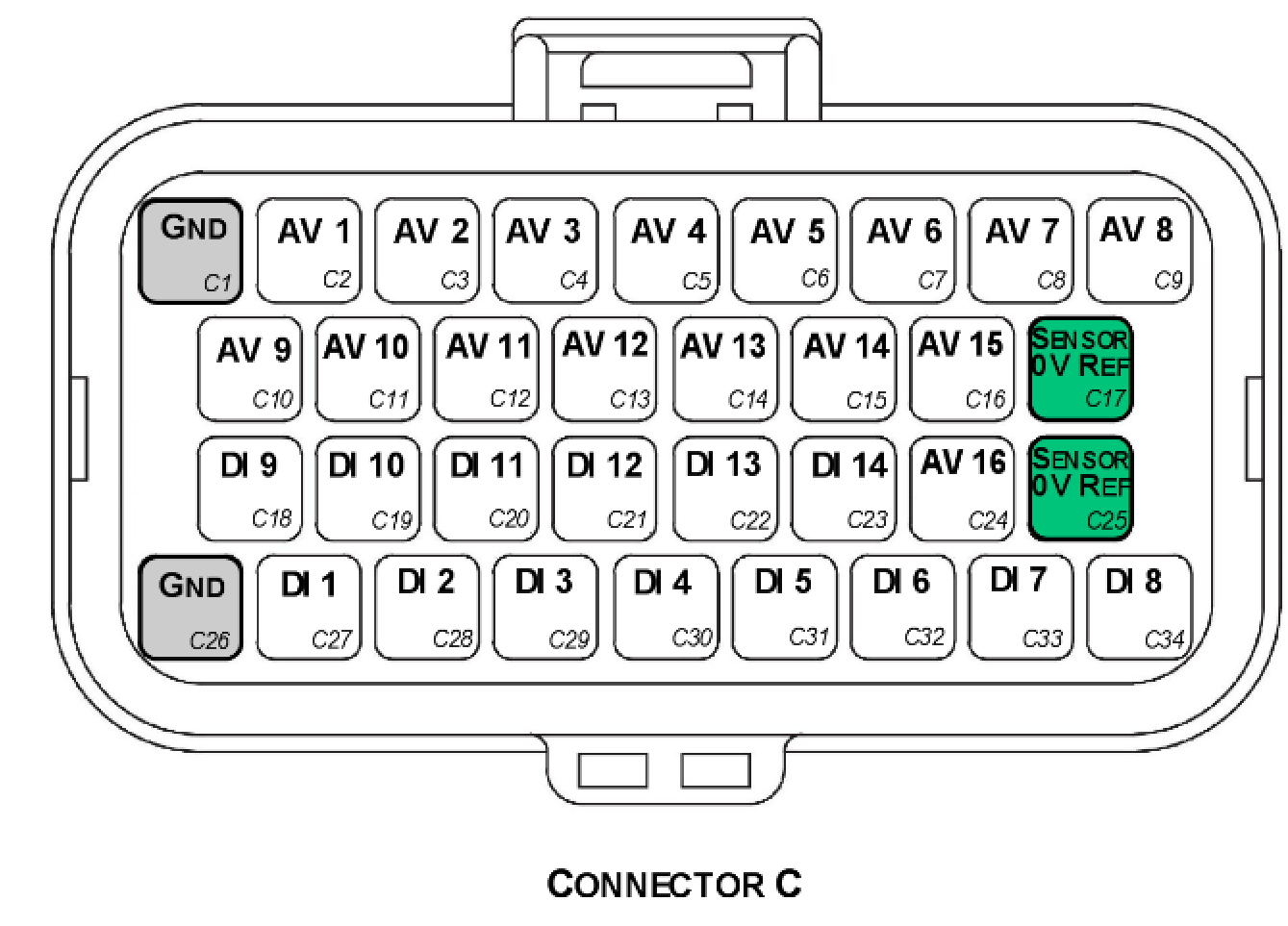
Connector C — TE Superseal 34 Way / Key 1.
4.1 Connector C Wire Colours
| Pin Name | Pin | Description | Colour | Wire Size (sq mm) |
|---|---|---|---|---|
| GND | C1 | Power Ground | Black | 0.85 |
| AV 1 | C2 | Analog Voltage CH 1 | White | 0.50 |
| AV 2 | C3 | Analog Voltage CH 2 | White | 0.50 |
| AV 3 | C4 | Analog Voltage CH 3 | White | 0.50 |
| AV 4 | C5 | Analog Voltage CH 4 | White | 0.50 |
| AV 5 | C6 | Analog Voltage CH 5 | White | 0.50 |
| AV 6 | C7 | Analog Voltage CH 6 | White | 0.50 |
| AV 7 | C8 | Analog Voltage CH 7 | White | 0.50 |
| AV 8 | C9 | Analog Voltage CH 8 | White | 0.50 |
| AV 9 | C10 | Analog Voltage CH 9 | White | 0.50 |
| AV 10 | C11 | Analog Voltage CH 10 | White | 0.50 |
| AV 11 | C12 | Analog Voltage CH 11 | White | 0.50 |
| AV 12 | C13 | Analog Voltage CH 12 | White | 0.50 |
| AV 13 | C14 | Analog Voltage CH 13 | White | 0.50 |
| AV 14 | C15 | Analog Voltage CH 14 | White | 0.50 |
| AV 15 | C16 | Analog Voltage CH 15 | White | 0.50 |
| GND OUT | C17 | Sensor 0V Ref (Branched Cable) | Black | 0.50 |
| DI 9 | C18 | Digital Input CH 9 | White | 0.50 |
| DI 10 | C19 | Digital Input CH 10 | White | 0.50 |
| DI 11 | C20 | Digital Input CH 11 | White | 0.50 |
| DI 12 | C21 | Digital Input CH 12 | White | 0.50 |
| DI 13 | C22 | Digital Input CH 13 | White | 0.50 |
| DI 14 | C23 | Digital Input CH 14 | White | 0.50 |
| AV 16 | C24 | Analog Voltage CH 16 | White | 0.50 |
| GND OUT | C25 | Sensor 0V Ref (Branched Cable) | Black | 0.50 |
| GND | C26 | Power Ground | Black | 0.85 |
| DI 1 | C27 | Digital Input CH 1 | White | 0.50 |
| DI 2 | C28 | Digital Input CH 2 | White | 0.50 |
| DI 3 | C29 | Digital Input CH 3 | White | 0.50 |
| DI 4 | C30 | Digital Input CH 4 | White | 0.50 |
| DI 5 | C31 | Digital Input CH 5 | White | 0.50 |
| DI 6 | C32 | Digital Input CH 6 | White | 0.50 |
| DI 7 | C33 | Digital Input CH 7 | White | 0.50 |
| DI 8 | C34 | Digital Input CH 8 | White | 0.50 |
4.2 Pin C17 and C25 Sensor Ground Branched Connections
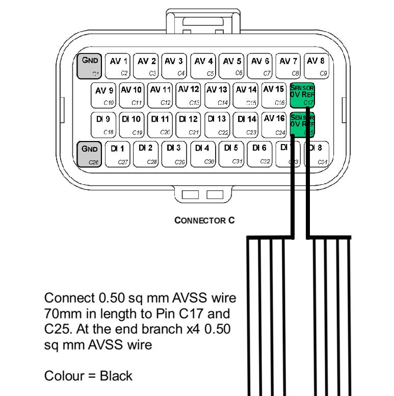
Connect a 0.50 sq mm AVSS wire, 70mm in length, to Pins C17 and C25. At the end, branch into x4 0.50 sq mm AVSS wires. Colour = Black.
5.0 Connector D
| Property | Value |
|---|---|
| Name | Superseal |
| Manufacturer | TE |
| Description | 26 Way / Key 1 |
| Part Number | 3-1437290-7 |
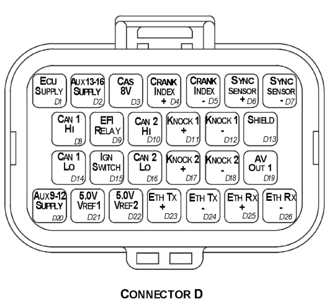
Connector D — TE Superseal 26 Way / Key 1.
5.1 Connector D Wire Colours
| Pin Name | Pin | Description | Colour | Wire Size (sq mm) |
|---|---|---|---|---|
| ECU SUPPLY | D1 | ECU Supply | Red | 0.85 |
| AUX 13-16 Supply | D2 | Power supply for Aux 13-16 | Red | 0.85 |
| CAS 8V | D3 | 8V Cas Supply | White/Orange | 0.50 |
| CRANK INDEX + | D4 | Crank Index position sensor Positive | 2 core Shielded Cable (shared with D5) | — |
| CRANK INDEX - | D5 | Crank Index position sensor Negative | 2 core Shielded Cable (shared with D4) | — |
| SYNC SENSOR + | D6 | Sync Sensor Positive | 2 core Shielded Cable (shared with D7) | — |
| SYNC SENSOR - | D7 | Sync Sensor Negative | 2 core Shielded Cable (shared with D6) | — |
| CAN 1 HI | D8 | Main Engine CAN | White | 0.50 |
| EFI RELAY | D9 | Main Relay Control | Grey | 0.50 |
| CAN 2 HI | D10 | Auxiliary CAN | White | |
| KNK 1 + | D11 | Knock Sensor 1 + | 2 core Shielded Cable (shared with D12) | — |
| KNK 1 - | D12 | Knock Sensor 1 - | 2 core Shielded Cable (shared with D11) | — |
| SHIELD | D13 | Crank/Sync/Knock Shield | White | 0.50 |
| CAN 1 LO | D14 | Main Engine CAN | Green | 0.50 |
| IGN SWITCH | D15 | Ignition Switch | Red | 0.50 |
| CAN 2 LO | D16 | Auxiliary CAN | Green | |
| KNK 2 + | D17 | Knock Sensor 2 + | 2 core Shielded Cable (shared with D18) | — |
| KNK 2 - | D18 | Knock Sensor 2 - | 2 core Shielded Cable (shared with D17) | — |
| AVOUT 1 | D19 | Analog Out 1 | White | |
| AUX 9-12 SUPPLY | D20 | Power supply for Aux 9-12 high side | Red | 0.85 |
| 5V ENG SUPPLY | D21 | Main 5V engine sensor supply (Branched) | Orange | 0.50 |
| 5V AUX SUPPLY | D22 | 5V auxiliary sensor supply | Orange | 0.50 |
| Ethernet TX+ | D23 | Twisted Pair CAT 5E | ||
| Ethernet TX- | D24 | Twisted Pair CAT 5E | ||
| Ethernet RX+ | D25 | Twisted Pair CAT 5E | ||
| Ethernet RX- | D26 | Twisted Pair CAT 5E |
5.2 Crank and Sync Shielded Cable Connections
- Use x1 2-core shielded cable for Pins D4 and D5
- Use x1 2-core shielded cable for Pins D6 and D7
NoteNOTE The individual core colours are not specified but there MUST be at least one different core colour between the Crank Index cable and Sync Sensor cable — i.e. the exact same cables cannot be used for both connections.
5.3 Knock Shielded Cable Connections
- Use x1 2-core shielded cable for Pins D11 and D12
- Use x1 2-core shielded cable for Pins D17 and D18
NoteNOTE The individual core colours are not specified but there MUST be at least one different core colour between the KNK 1 cable and KNK 2 cable — i.e. the exact same cables cannot be used for both connections. Ideally these core colours should also be different to those used in section 5.2.
5.4 5V Eng Supply Branched Connections (Pin D21)
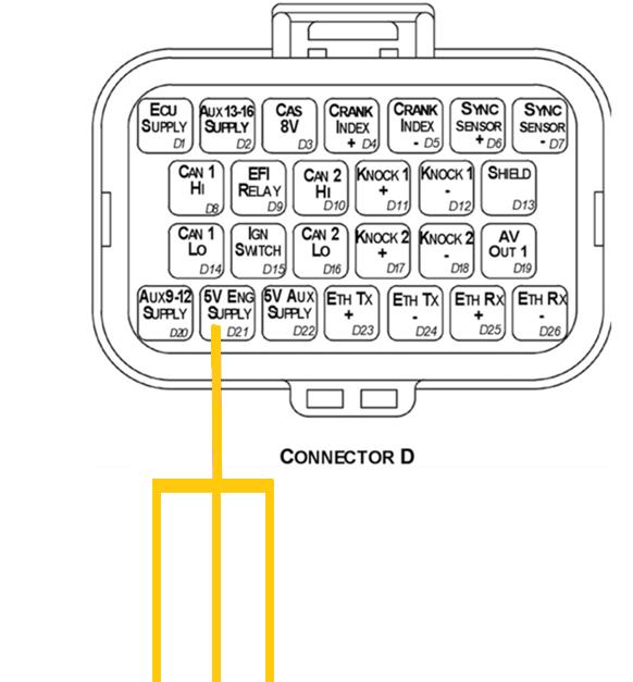
Pin D21 (5V Eng Supply) is a branched connection feeding the engine sensor 5V supply.
5.5 Ethernet Sub Harness - Pins D23-D26
See the document “Ethernet to Superseal Loom Specification V1.x”. This sub harness should be plugged into Connector D, Pins D23 → D26.
Appendix A – KV8 ECU Pinout Drawing
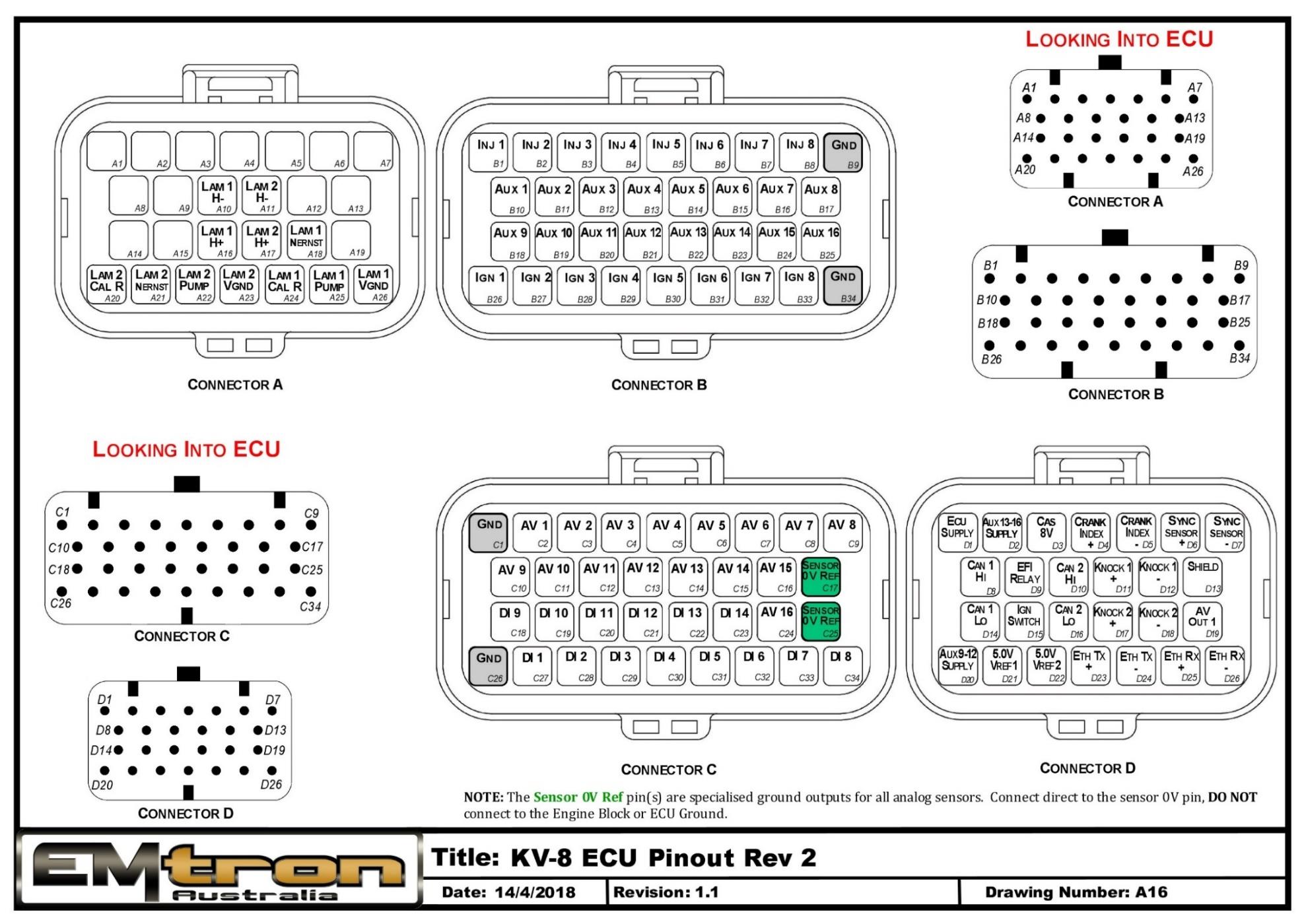
KV8 ECU pinout (Rev 2) — Connectors A, B, C and D, looking into the ECU.
Appendix B – KV12 ECU Pinout Drawing
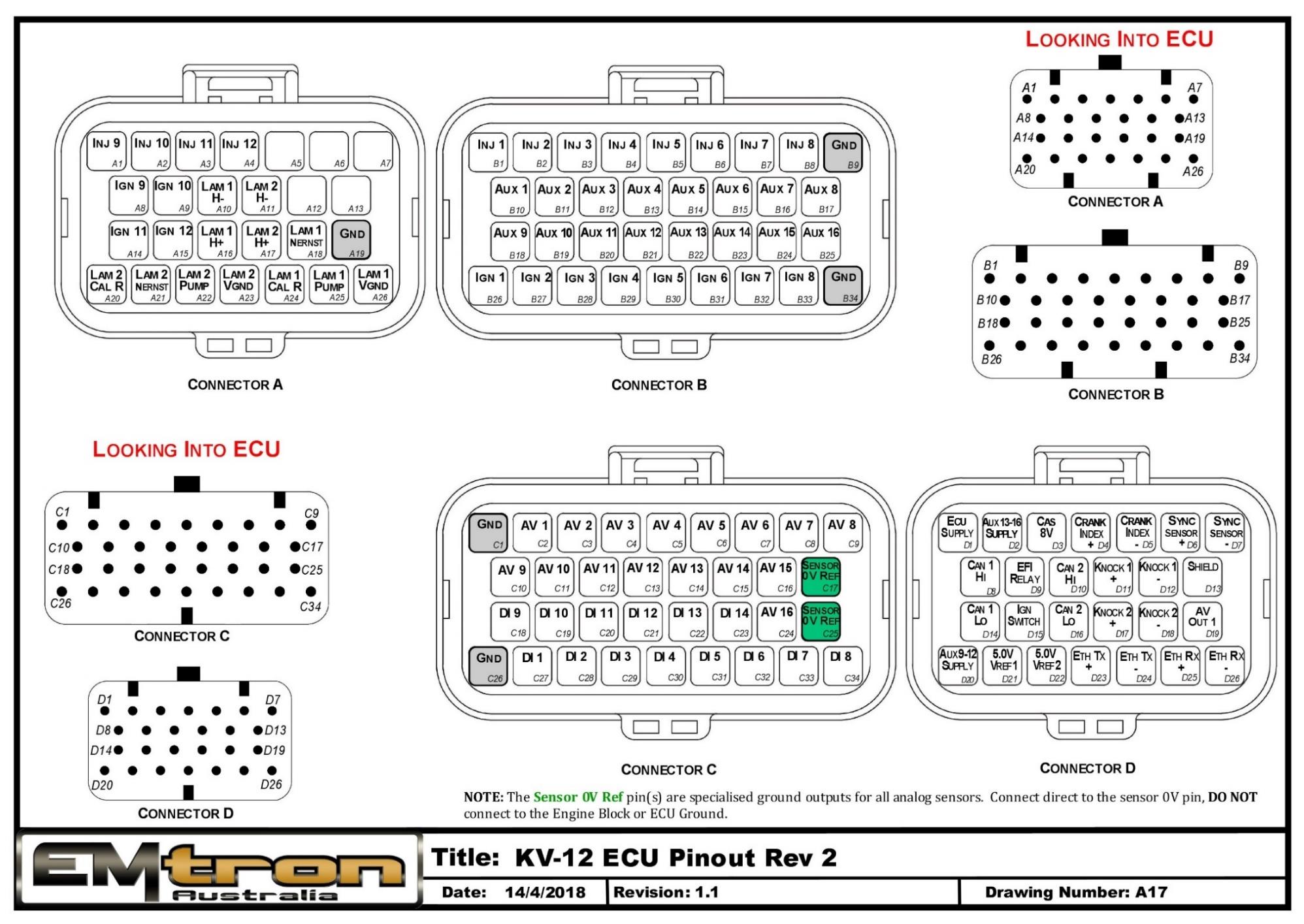
KV12 ECU pinout (Rev 2) — Connectors A, B, C and D, looking into the ECU.
Appendix C – KV16 ECU Pinout Drawing
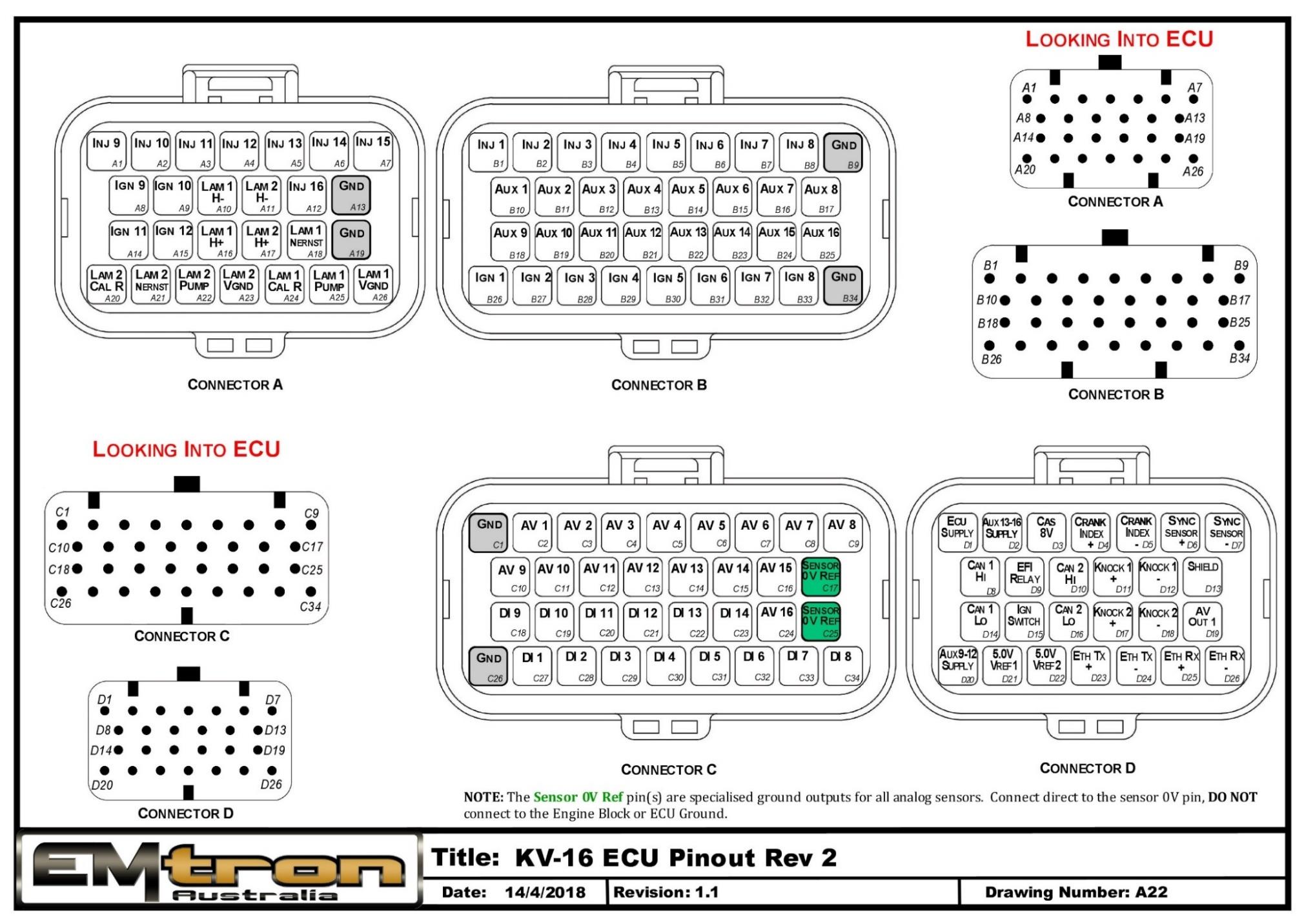
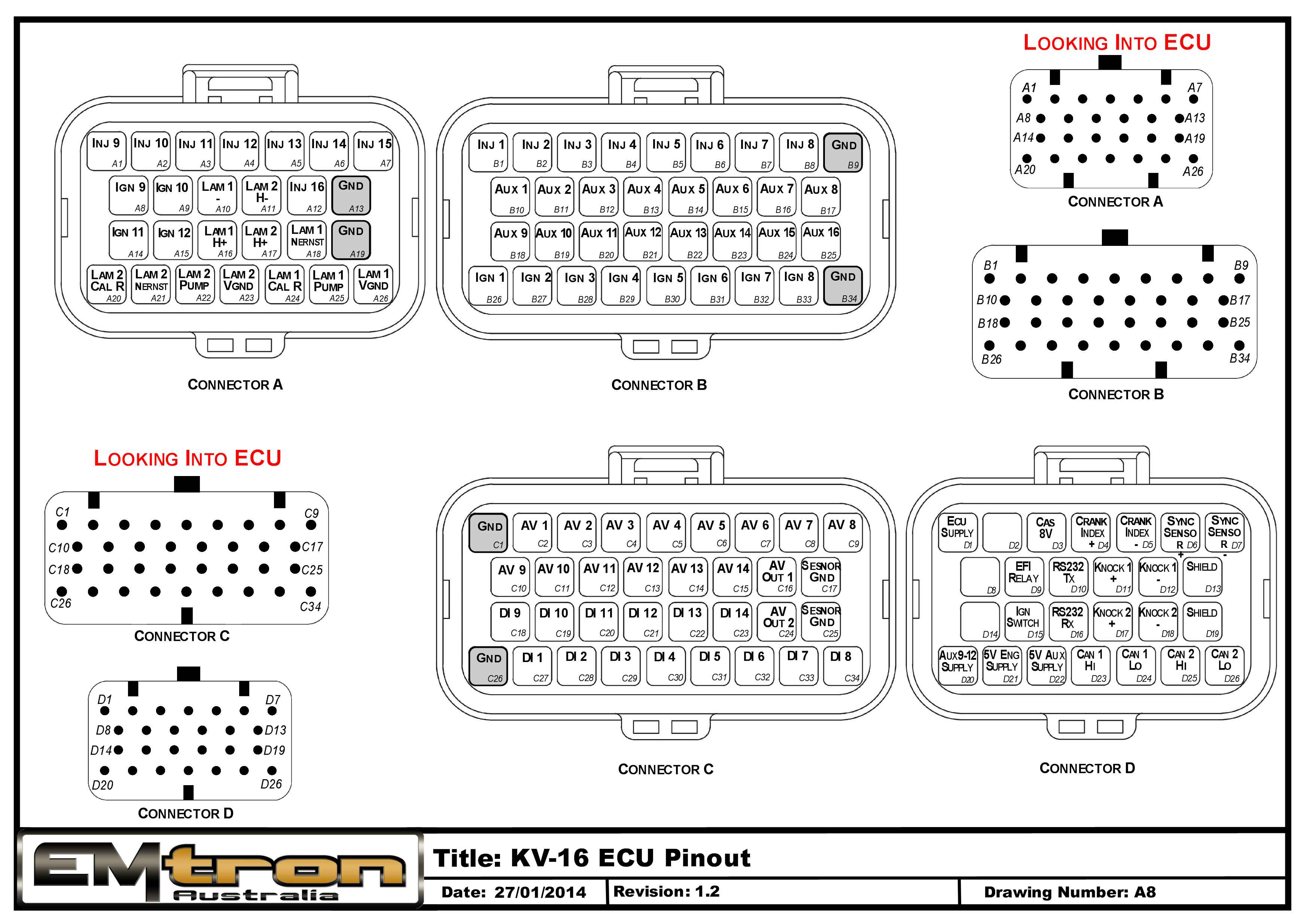
KV16 ECU pinout (Rev 2) — Connectors A, B, C and D, looking into the ECU.
Appendix D – KV Series ECU Wiring
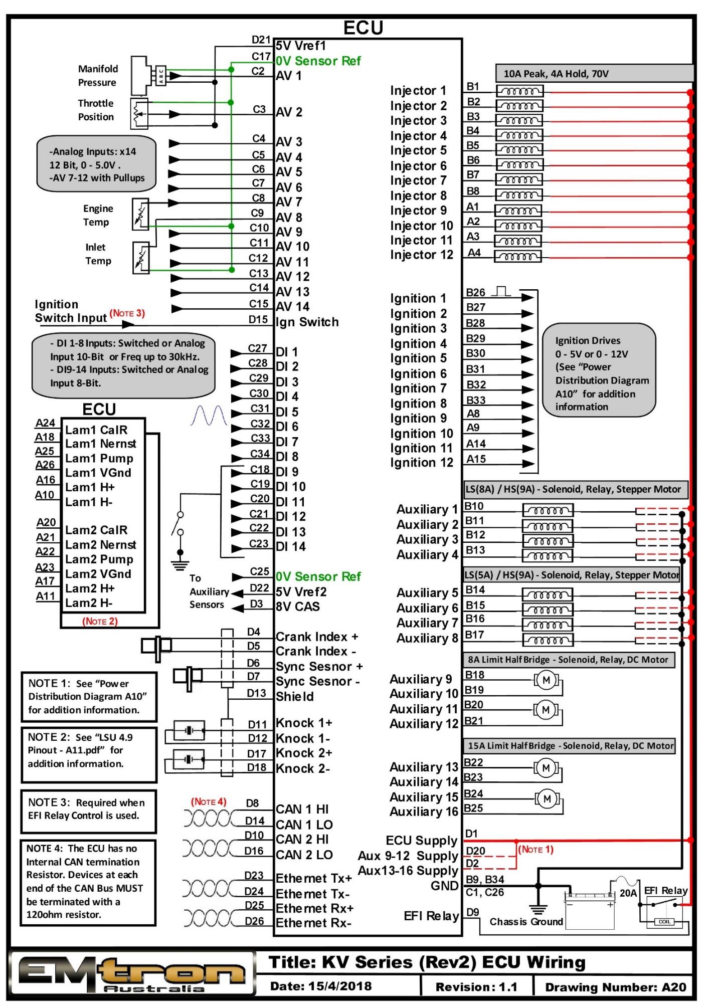
KV Series (Rev 2) ECU wiring overview (drawing A20).
Appendix E – KV Series Ethernet Wiring
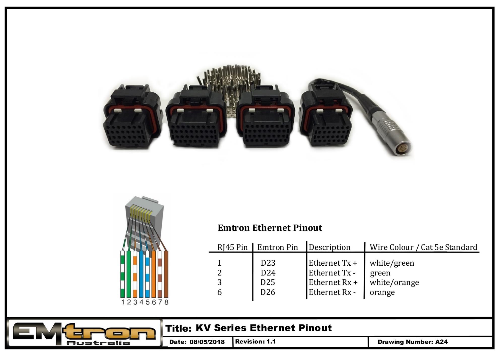
KV Series Ethernet wiring / tuning cable pinout (drawing A24).
KV Revision 1 ECU
Revision 1 KV Series ECU has the Ethernet Communications port at the rear of the ECU.
Revision 2 KV Series ECU has the Ethernet Communications port at the front of the ECU in Connector D
KV Series Power Distribution
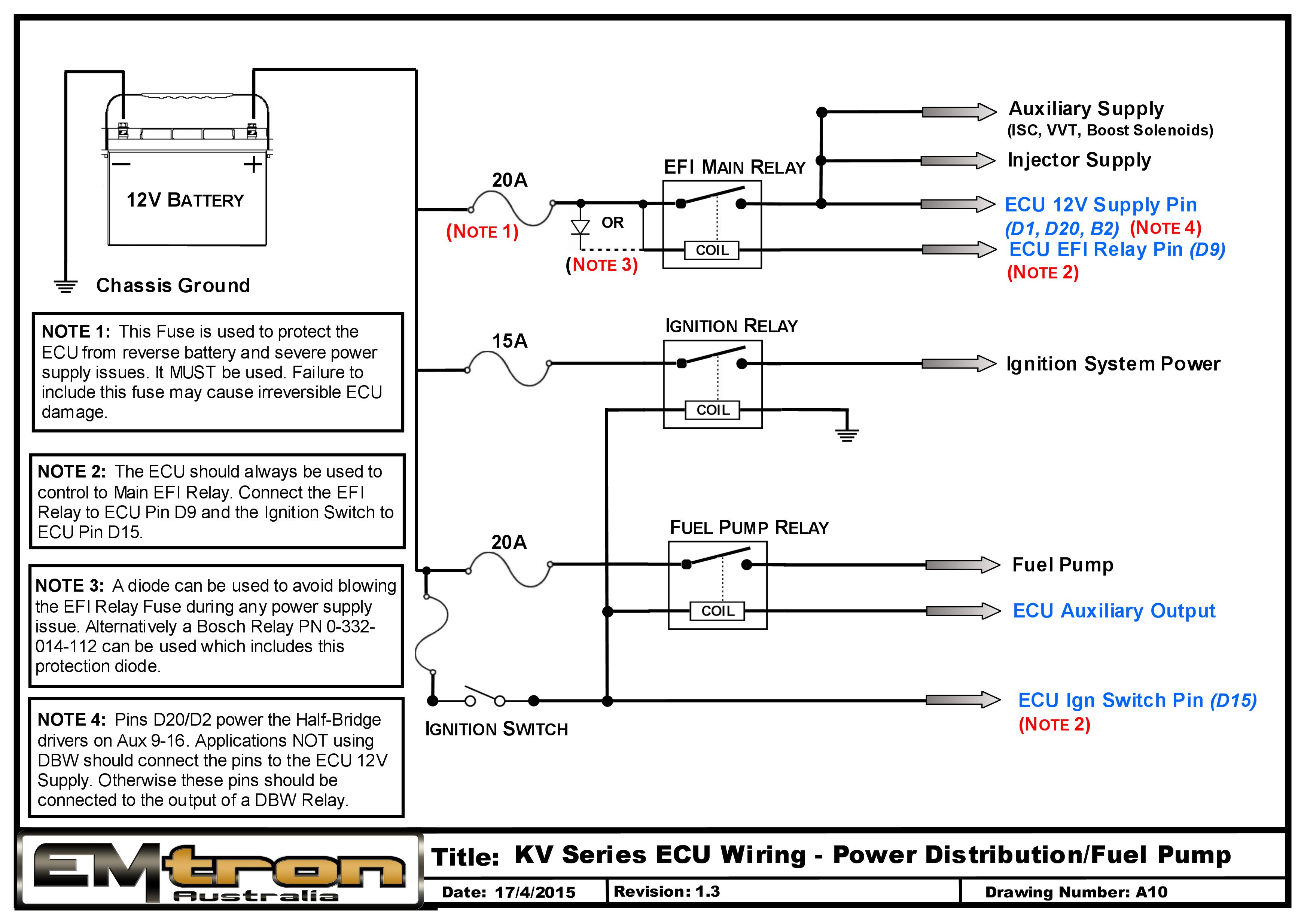
SL Series
Subsections of SL Series
SL4 Pinout
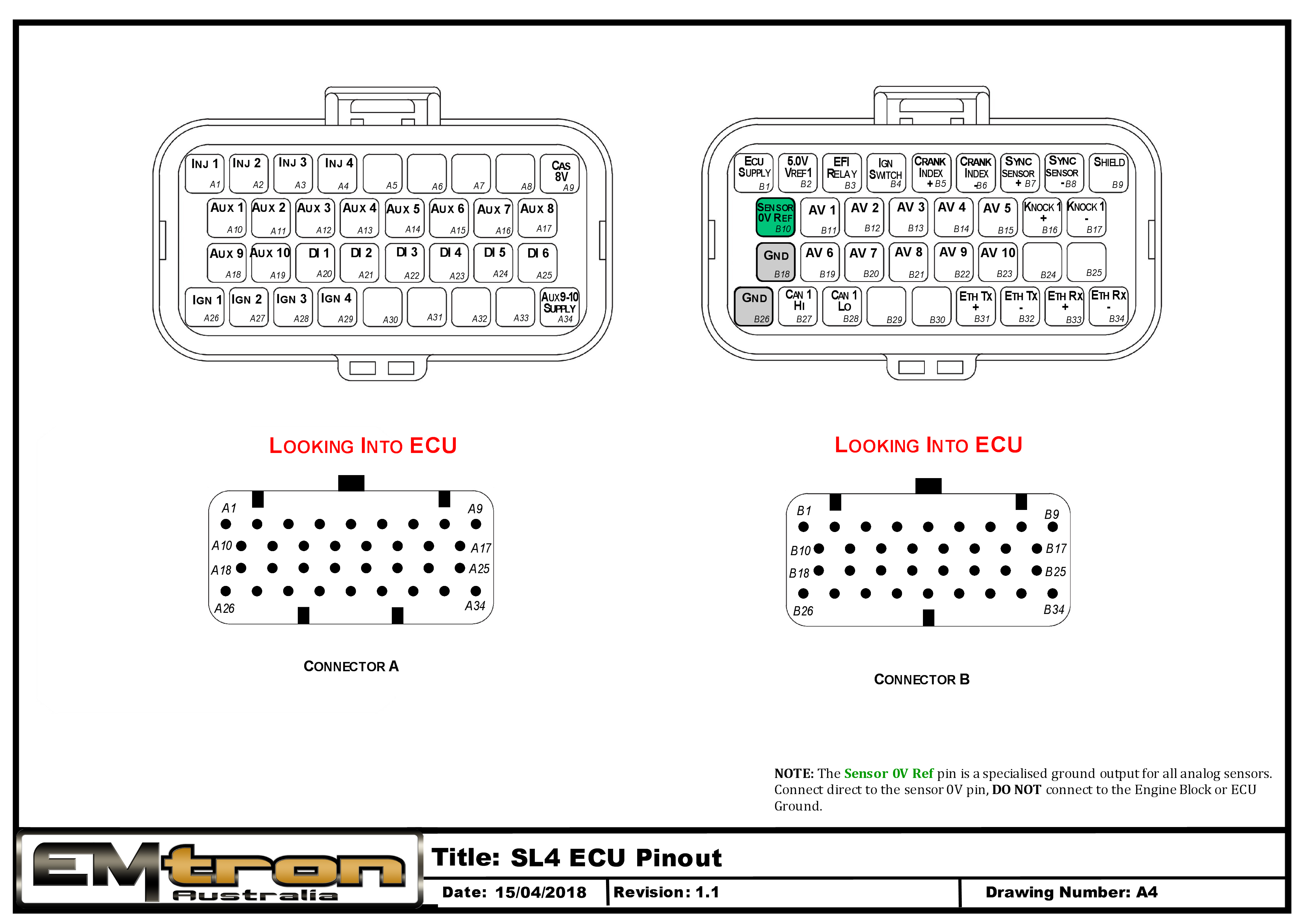
Pin Descriptions
| Connector A: Injection/Ignition/Auxiliary Outputs (15.0A Max continuous current - wire gauge dependant) |
|---|
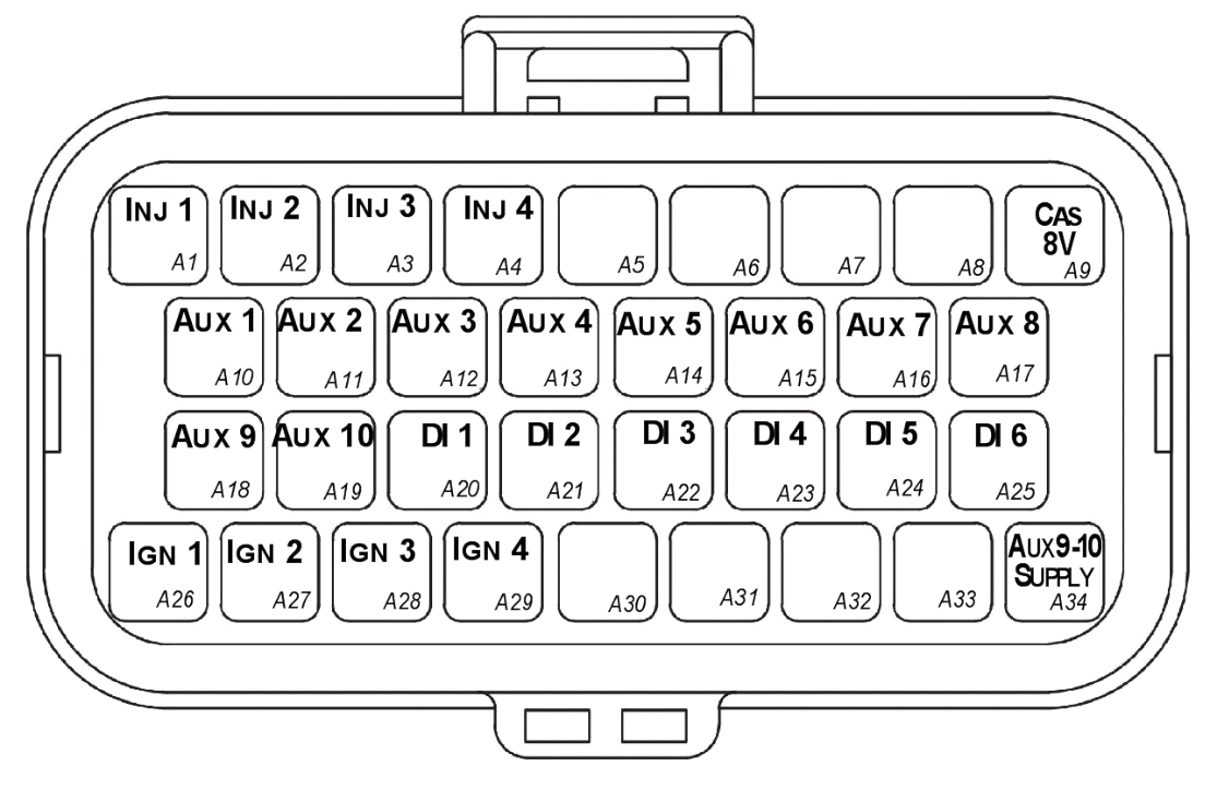
Looking into ECU connector
| Pin | Channel Name | Pin | Channel Name |
|---|---|---|---|
| A1 | Injection Channel 1 | A18 | Auxiliary Output 9 |
| A2 | Injection Channel 2 | A19 | Auxiliary Output 10 |
| A3 | Injection Channel 3 | A20 | Digital Input 1 |
| A4 | Injection Channel 4 | A21 | Digital Input 2 |
| A5 | NC | A22 | Digital Input 3 |
| A6 | NC | A23 | Digital Input 4 |
| A7 | NC | A24 | Digital Input 5 |
| A8 | NC | A25 | Digital Input 6 |
| A9 | Sensor Supply 8V | A26 | Ignition Channel 1 |
| A10 | Auxiliary Output 1 | A27 | Ignition Channel 2 |
| A11 | Auxiliary Output 2 | A28 | Ignition Channel 3 |
| A12 | Auxiliary Output 3 | A29 | Ignition Channel 4 |
| A13 | Auxiliary Output 4 | A30 | NC |
| A14 | Auxiliary Output 5 | A31 | NC |
| A15 | Auxiliary Output 6 | A32 | NC |
| A16 | Auxiliary Output 7 | A33 | NC |
| A17 | Auxiliary Output 8 | A34 | Auxiliary Output 9-10, 14V Supply |
| Connector B: Signal/Power/Communications/Triggers/Knock (15.0A Max continuous current - wire gauge dependant) |
|---|
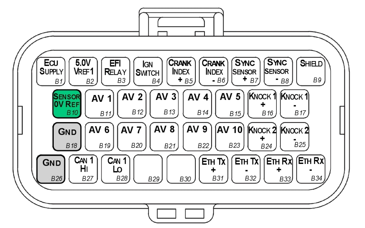
Looking into ECU connector
| Pin | Channel Name | Pin | Channel Name |
|---|---|---|---|
| B1 | ECU 14V Supply | B18 | ECU Ground |
| B2 | Sensor Supply Vref1: 5.0V | B19 | Analog Input Channel 6 |
| B3 | EFI Relay Output (Low Side 200mA) | B20 | Analog Input Channel 7 |
| B4 | Ignition Switch Input | B21 | Analog Input Channel 8 |
| B5 | Crank Index Sensor + | B22 | Analog Input Channel 9 |
| B6 | Crank Index Sensor - | B23 | Analog Input Channel 10 |
| B7 | Sync Sensor + | B24 | Knock 2 + |
| B8 | Sync Sensor - | B25 | Knock 2 - |
| B9 | Shield (Crank/Sync/ Knock) | B26 | ECU Ground |
| B10 | Analog Sensor 0V Reference | B27 | CAN 1H |
| B11 | Analog Input Channel 1 | B28 | CAN 1L |
| B12 | Analog Input Channel 2 | B29 | NC |
| B13 | Analog Input Channel 3 | B30 | NC |
| B14 | Analog Input Channel 4 | B31 | Ethernet Tx + |
| B15 | Analog Input Channel 5 | B32 | Ethernet Tx - |
| B16 | Knock 1 + | B33 | Ethernet Rx + |
| B17 | Knock 1 - | B34 | Ethernet Rx - |
Important Notes
Analog Sensor 0V Reference (Pin B10)
This pin should be connected directly to the 0V (Ground) pin on any low current analog sensor, for example Pressure or Temperature.
- DO NOT connect the ECU pin B10 directly to the Engine Block or ECU Ground. These are dedicated and specialised ground outputs for all analog channels and should be connected directly to the sensor.
- DO NOT connect frequency-based sensors to these pins; for example, an Ethanol content sensor. The sensor 0V pin should be connected to the ECU ground.
Half Bridge Driver Power Supply Input (Pin A34)
Pin A34 is a dedicated power supply for Auxiliary Channels 9-10. Power must be supplied to this pin for these channels to operate correctly. In non-DBW (Drive by Wire) applications the ECU Supply power can be shared, assuming the wire gauge has a sufficient rating for the current demand. In DBW applications power to this pin MUST come from an ECU controlled DBW Relay.
SL6 Pinout
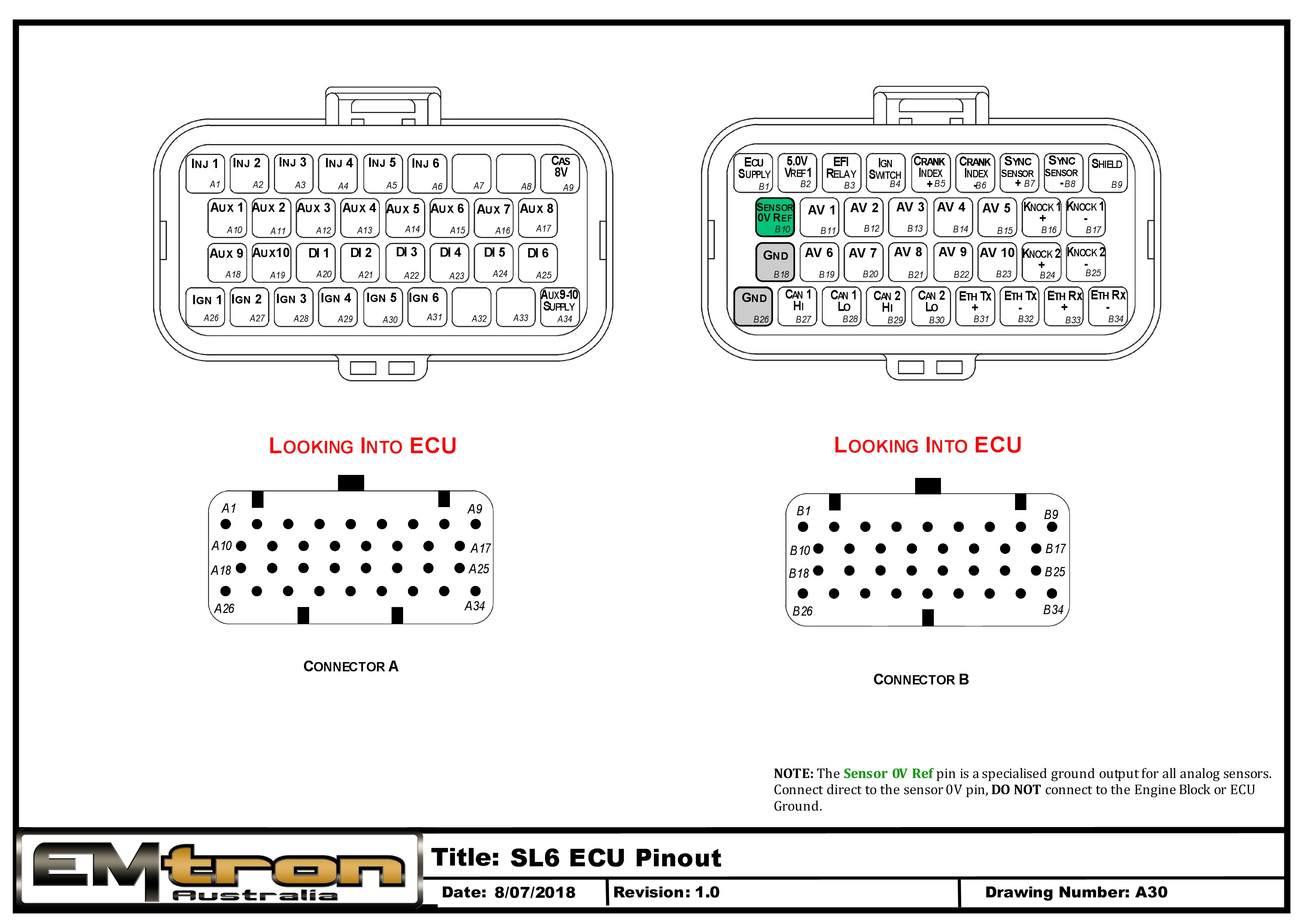
Pin Descriptions
| Connector A: Injection/Ignition/Auxiliary Outputs (15.0A Max continuous current - wire gauge dependant) |
|---|
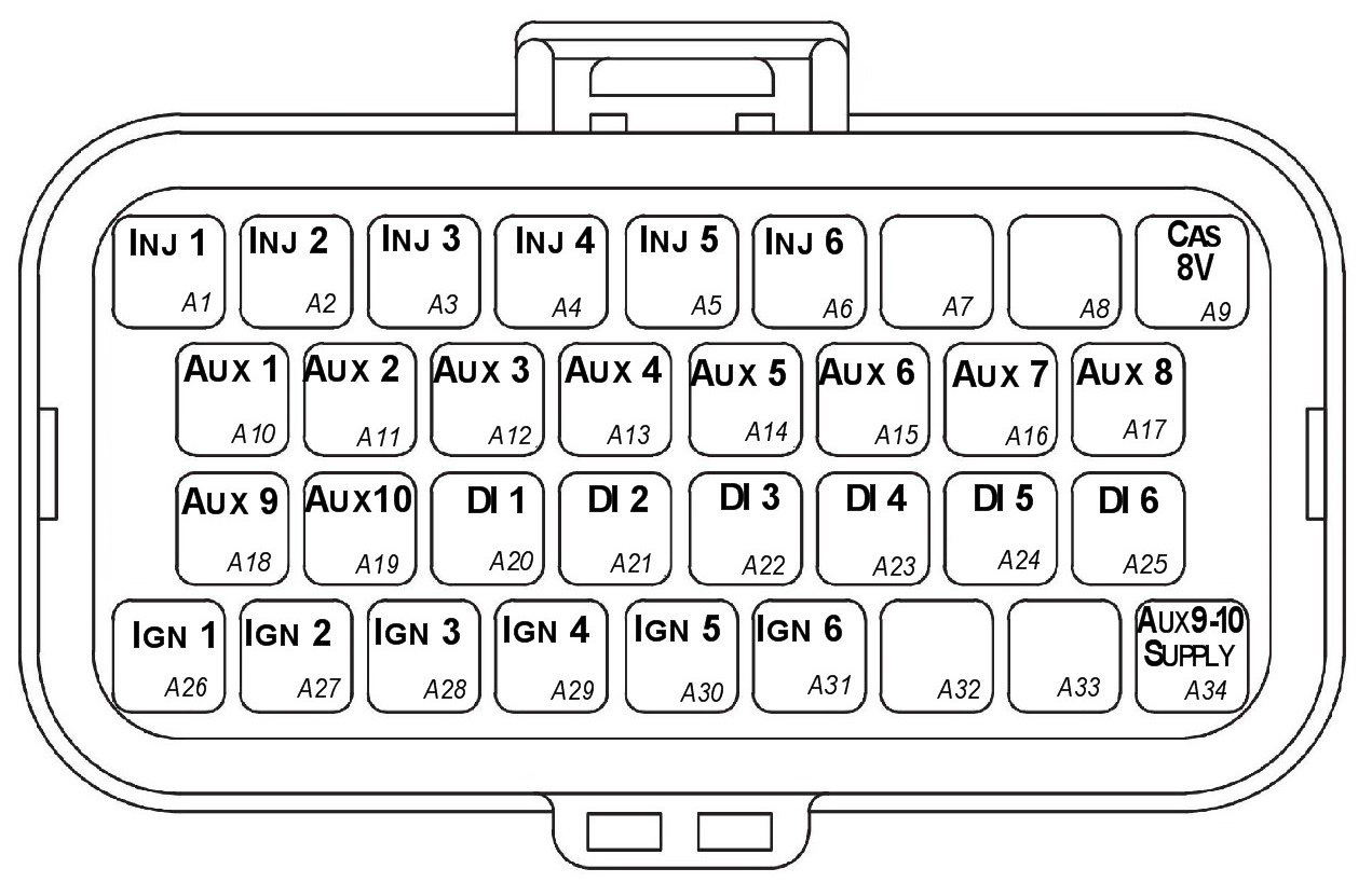
Looking into ECU connector
| Pin | Channel Name | Pin | Channel Name |
|---|---|---|---|
| A1 | Injection Channel 1 | A18 | Auxiliary Output 9 |
| A2 | Injection Channel 2 | A19 | Auxiliary Output 10 |
| A3 | Injection Channel 3 | A20 | Digital Input 1 |
| A4 | Injection Channel 4 | A21 | Digital Input 2 |
| A5 | Injection Channel 5 | A22 | Digital Input 3 |
| A6 | Injection Channel 6 | A23 | Digital Input 4 |
| A7 | NC | A24 | Digital Input 5 |
| A8 | NC | A25 | Digital Input 6 |
| A9 | Sensor Supply 8V | A26 | Ignition Channel 1 |
| A10 | Auxiliary Output 1 | A27 | Ignition Channel 2 |
| A11 | Auxiliary Output 2 | A28 | Ignition Channel 3 |
| A12 | Auxiliary Output 3 | A29 | Ignition Channel 4 |
| A13 | Auxiliary Output 4 | A30 | Ignition Channel 5 |
| A14 | Auxiliary Output 5 | A31 | Ignition Channel 6 |
| A15 | Auxiliary Output 6 | A32 | NC |
| A16 | Auxiliary Output 7 | A33 | NC |
| A17 | Auxiliary Output 8 | A34 | Auxiliary Output 9-10, 14V Supply |
| Connector B: Signal/Power/Communications/Triggers/Knock (15.0A Max continuous current - wire gauge dependant) |
|---|
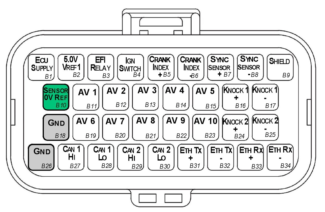
Looking into ECU connector
| Pin | Channel Name | Pin | Channel Name |
|---|---|---|---|
| B1 | ECU 14V Supply | B18 | ECU Ground |
| B2 | Sensor Supply Vref1: 5.0V | B19 | Analog Input Channel 6 |
| B3 | EFI Relay Output (Low Side 200mA) | B20 | Analog Input Channel 7 |
| B4 | Ignition Switch Input | B21 | Analog Input Channel 8 |
| B5 | Crank Index Sensor + | B22 | Analog Input Channel 9 |
| B6 | Crank Index Sensor - | B23 | Analog Input Channel 10 |
| B7 | Sync Sensor + | B24 | Knock 2 + |
| B8 | Sync Sensor - | B25 | Knock 2 - |
| B9 | Shield (Crank/Sync/ Knock) | B26 | ECU Ground |
| B10 | Analog Sensor 0V Reference | B27 | CAN 1H |
| B11 | Analog Input Channel 1 | B28 | CAN 1L |
| B12 | Analog Input Channel 2 | B29 | NC |
| B13 | Analog Input Channel 3 | B30 | NC |
| B14 | Analog Input Channel 4 | B31 | Ethernet Tx + |
| B15 | Analog Input Channel 5 | B32 | Ethernet Tx - |
| B16 | Knock 1 + | B33 | Ethernet Rx + |
| B17 | Knock 1 - | B34 | Ethernet Rx - |
Important Notes
Analog Sensor 0V Reference (Pin B10)
This pin should be connected directly to the 0V (Ground) pin on any low current analog sensor, for example Pressure or Temperature.
- DO NOT connect the ECU pin B10 directly to the Engine Block or ECU Ground. These are dedicated and specialised ground outputs for all analog channels and should be connected directly to the sensor.
- DO NOT connect frequency-based sensors to these pins; for example, an Ethanol content sensor. The sensor 0V pin should be connected to the ECU ground.
Half Bridge Driver Power Supply Input (Pin A34)
Pin A34 is a dedicated power supply for Auxiliary Channels 9-10. Power must be supplied to this pin for these channels to operate correctly. In non-DBW (Drive by Wire) applications the ECU Supply power can be shared, assuming the wire gauge has a sufficient rating for the current demand. In DBW applications power to this pin MUST come from an ECU controlled DBW Relay.
SL8 Pinout
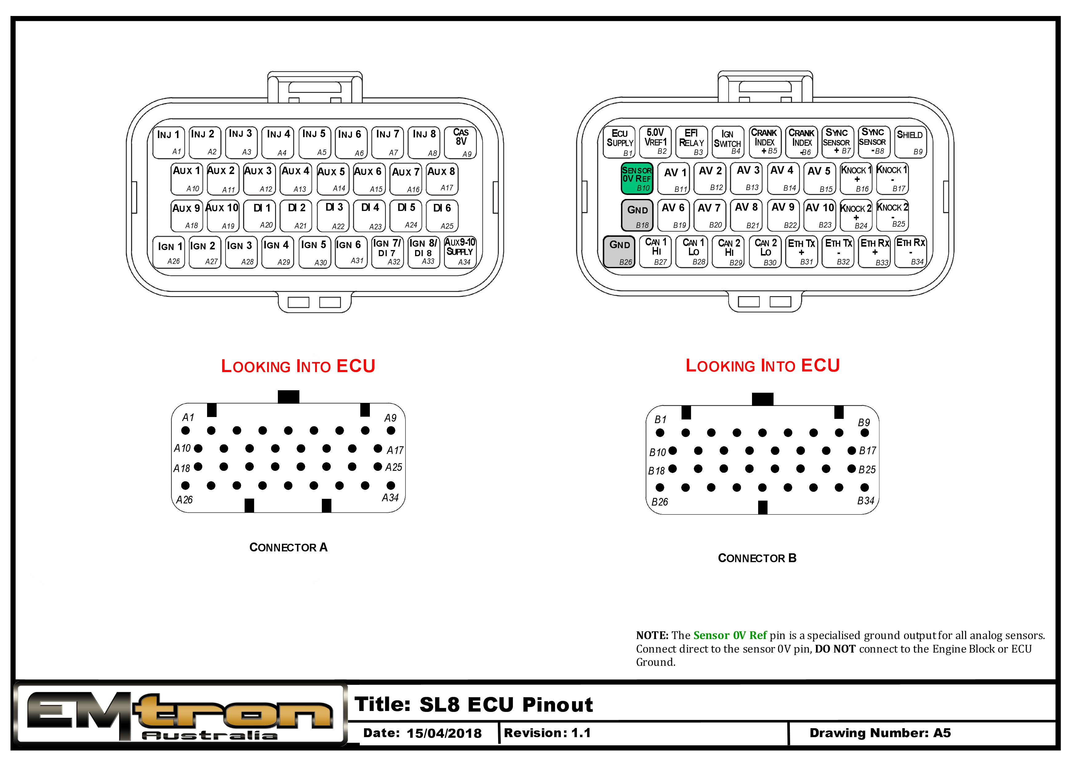
Pin Descriptions
| Connector A: Injection/Ignition/Auxiliary Outputs (15.0A Max continuous current - wire gauge dependant) |
|---|
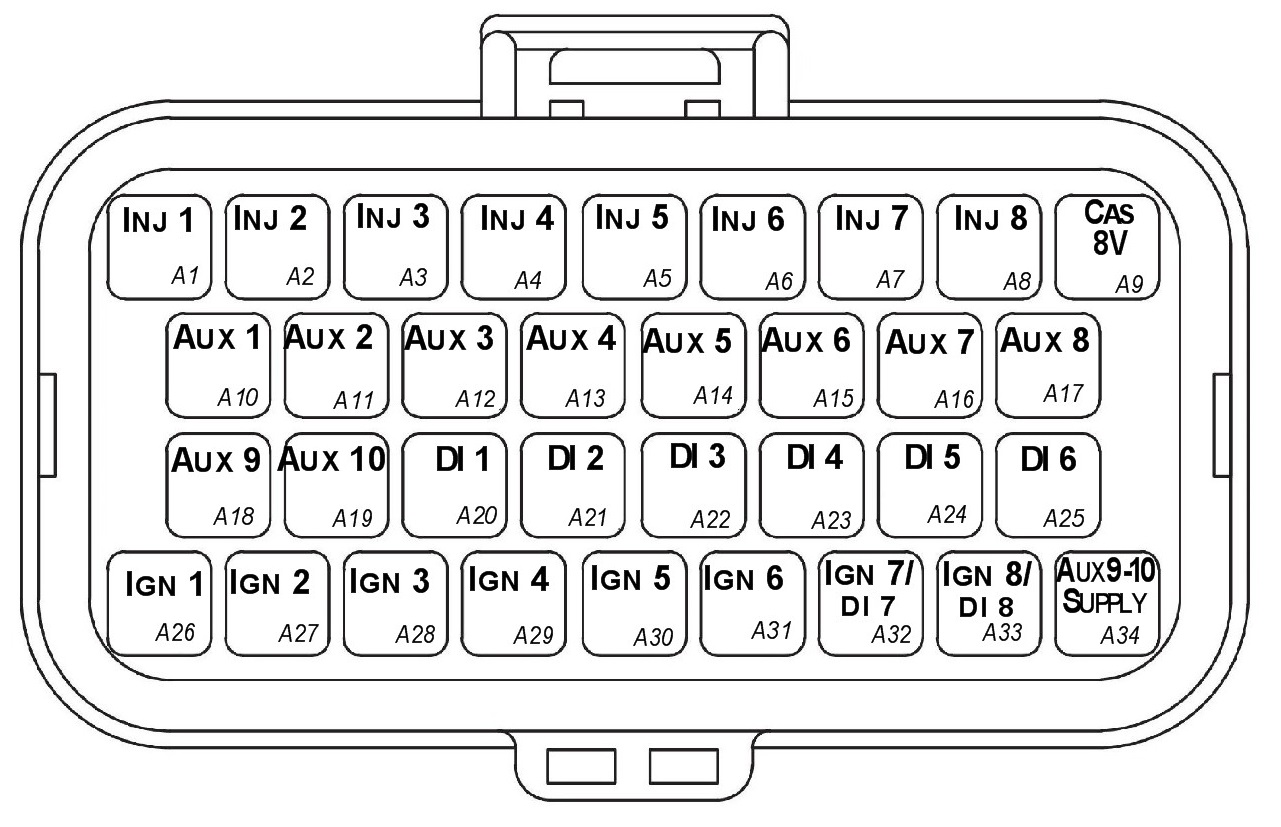
Looking into ECU connector
| Pin | Channel Name | Pin | Channel Name |
|---|---|---|---|
| A1 | Injection Channel 1 | A18 | Auxiliary Output 9 |
| A2 | Injection Channel 2 | A19 | Auxiliary Output 10 |
| A3 | Injection Channel 3 | A20 | Digital Input 1 |
| A4 | Injection Channel 4 | A21 | Digital Input 2 |
| A5 | Injection Channel 5 | A22 | Digital Input 3 |
| A6 | Injection Channel 6 | A23 | Digital Input 4 |
| A7 | Injection Channel 7 | A24 | Digital Input 5 |
| A8 | Injection Channel 8 | A25 | Digital Input 6 |
| A9 | Sensor Supply 8V | A26 | Ignition Channel 1 |
| A10 | Auxiliary Output 1 | A27 | Ignition Channel 2 |
| A11 | Auxiliary Output 2 | A28 | Ignition Channel 3 |
| A12 | Auxiliary Output 3 | A29 | Ignition Channel 4 |
| A13 | Auxiliary Output 4 | A30 | Ignition Channel 5 |
| A14 | Auxiliary Output 5 | A31 | Ignition Channel 6 |
| A15 | Auxiliary Output 6 | A32 | Ignition Channel 7 |
| A16 | Auxiliary Output 7 | A33 | Ignition Channel 8 |
| A17 | Auxiliary Output 8 | A34 | Auxiliary Output 9-10, 14V Supply |
| Connector B: Signal/Power/Communications/Triggers/Knock (15.0A Max continuous current - wire gauge dependant) |
|---|
Looking into ECU connector
| Pin | Channel Name | Pin | Channel Name |
|---|---|---|---|
| B1 | ECU 14V Supply | B18 | ECU Ground |
| B2 | Sensor Supply Vref1: 5.0V | B19 | Analog Input Channel 6 |
| B3 | EFI Relay Output (Low Side 200mA) | B20 | Analog Input Channel 7 |
| B4 | Ignition Switch Input | B21 | Analog Input Channel 8 |
| B5 | Crank Index Sensor + | B22 | Analog Input Channel 9 |
| B6 | Crank Index Sensor - | B23 | Analog Input Channel 10 |
| B7 | Sync Sensor + | B24 | Knock 2 + |
| B8 | Sync Sensor - | B25 | Knock 2 - |
| B9 | Shield (Crank/Sync/ Knock) | B26 | ECU Ground |
| B10 | Analog Sensor 0V Reference | B27 | CAN 1H |
| B11 | Analog Input Channel 1 | B28 | CAN 1L |
| B12 | Analog Input Channel 2 | B29 | NC |
| B13 | Analog Input Channel 3 | B30 | NC |
| B14 | Analog Input Channel 4 | B31 | Ethernet Tx + |
| B15 | Analog Input Channel 5 | B32 | Ethernet Tx - |
| B16 | Knock 1 + | B33 | Ethernet Rx + |
| B17 | Knock 1 - | B34 | Ethernet Rx - |
Important Notes
Analog Sensor 0V Reference (Pin B10)
This pin should be connected directly to the 0V (Ground) pin on any low current analog sensor, for example Pressure or Temperature.
- DO NOT connect the ECU pin B10 directly to the Engine Block or ECU Ground. These are dedicated and specialised ground outputs for all analog channels and should be connected directly to the sensor.
- DO NOT connect frequency-based sensors to these pins; for example, an Ethanol content sensor. The sensor 0V pin should be connected to the ECU ground.
Half Bridge Driver Power Supply Input (Pin A34)
Pin A34 is a dedicated power supply for Auxiliary Channels 9-10. Power must be supplied to this pin for these channels to operate correctly. In non-DBW (Drive by Wire) applications the ECU Supply power can be shared, assuming the wire gauge has a sufficient rating for the current demand. In DBW applications power to this pin MUST come from an ECU controlled DBW Relay.
SL Series Wiring Harness Specification
1.0 Introduction
This document contains the specification for the Emtron SL Series wiring harness.
- Loom Length = 2.5 meters
- Wire Type = AVSS
NoteNOTE Any unused pins MUST have blanking bungs fitted to the connector to keep the plug rated at its IP standard.
2.0 Connector A
| Property | Value |
|---|---|
| Name | Superseal |
| Manufacturer | TE |
| Description | 34 Way / Key 2 |
| Part Number | 4-1437290-1 |
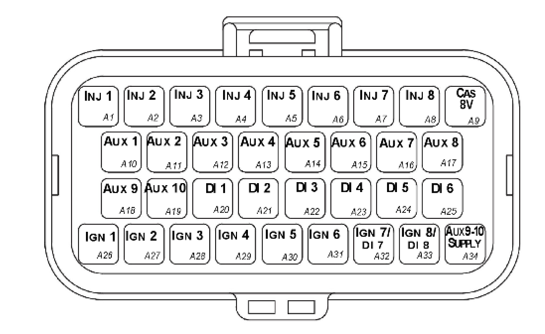
Connector A — TE Superseal 34 Way / Key 2.
2.1 Connector A Wire Colours
| Pin Name | Pin | Description | Colour | Wire Size (sq mm) |
|---|---|---|---|---|
| INJ 1 | A1 | Injector Channel 1 | Blue | 0.50 |
| INJ 2 | A2 | Injector Channel 2 | Blue | 0.50 |
| INJ 3 | A3 | Injector Channel 3 | Blue | 0.50 |
| INJ 4 | A4 | Injector Channel 4 | Blue | 0.50 |
| INJ 5 | A5 | Injector Channel 5 | Blue | 0.50 |
| INJ 6 | A6 | Injector Channel 6 | Blue | 0.50 |
| INJ 7 | A7 | Injector Channel 7 | Blue | 0.50 |
| INJ 8 | A8 | Injector Channel 8 | Blue | 0.50 |
| CAS 8V | A9 | 8V Cas Supply | White/Orange | 0.50 |
| AUX 1 | A10 | Auxiliary Channel 1 | Grey | 0.50 |
| AUX 2 | A11 | Auxiliary Channel 2 | Grey | 0.50 |
| AUX 3 | A12 | Auxiliary Channel 3 | Grey | 0.50 |
| AUX 4 | A13 | Auxiliary Channel 4 | Grey | 0.50 |
| AUX 5 | A14 | Auxiliary Channel 5 | Grey | 0.50 |
| AUX 6 | A15 | Auxiliary Channel 6 | Grey | 0.50 |
| AUX 7 | A16 | Auxiliary Channel 7 | Grey | 0.50 |
| AUX 8 | A17 | Auxiliary Channel 8 | Grey | 0.50 |
| AUX 9 | A18 | Auxiliary Channel 9 | Grey | 0.50 |
| AUX 10 | A19 | Auxiliary Channel 10 | Grey | 0.50 |
| DI 1 | A20 | Digital Input CH 1 | White | 0.50 |
| DI 2 | A21 | Digital Input CH 2 | White | 0.50 |
| DI 3 | A22 | Digital Input CH 3 | White | 0.50 |
| DI 4 | A23 | Digital Input CH 4 | White | 0.50 |
| DI 5 | A24 | Digital Input CH 5 | White | 0.50 |
| DI 6 | A25 | Digital Input CH 6 | White | 0.50 |
| IGN 1 | A26 | Ignition Channel 1 | Yellow | 0.50 |
| IGN 2 | A27 | Ignition Channel 2 | Yellow | 0.50 |
| IGN 3 | A28 | Ignition Channel 3 | Yellow | 0.50 |
| IGN 4 | A29 | Ignition Channel 4 | Yellow | 0.50 |
| IGN 5 | A30 | Ignition Channel 5 | Yellow | 0.50 |
| IGN 6 | A31 | Ignition Channel 6 | Yellow | 0.50 |
| IGN 7 / DI 7 | A32 | Ignition Channel 7 | Yellow | 0.50 |
| IGN 8 / DI 8 | A33 | Ignition Channel 8 | Yellow | 0.50 |
| AUX 9-10 SUPPLY | A34 | Power supply for Aux 9-10 high side | Red | 0.85 |
3.0 Connector B
| Property | Value |
|---|---|
| Name | Superseal |
| Manufacturer | TE |
| Description | 34 Way / Key 1 |
| Part Number | 4-1437290-0 |
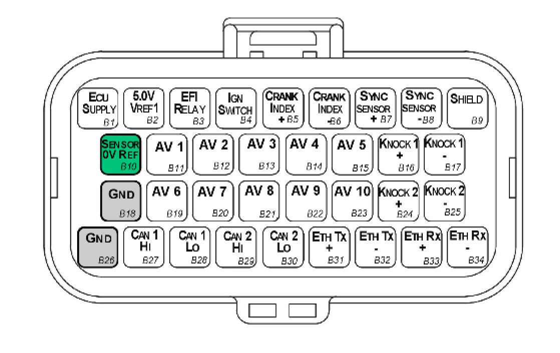
Connector B — TE Superseal 34 Way / Key 1.
3.1 Connector B Wire Colours
| Pin Name | Pin | Description | Colour | Wire Size (sq mm) |
|---|---|---|---|---|
| ECU SUPPLY | B1 | ECU Supply | Red | 0.85 |
| 5V SUPPLY | B2 | Main 5V engine sensor supply (Branched) | Orange | 0.50 |
| EFI RELAY | B3 | Main Relay Control | Pink/Black | 0.50 |
| IGN SWITCH | B4 | Ignition Switch | Red | 0.50 |
| CRANK INDEX + | B5 | Crank Index position sensor Positive | 2 core Shielded Cable (shared with B6) | — |
| CRANK INDEX - | B6 | Crank Index position sensor Negative | 2 core Shielded Cable (shared with B5) | — |
| SYNC SENSOR + | B7 | Sync Sensor Positive | 2 core Shielded Cable (shared with B8) | — |
| SYNC SENSOR - | B8 | Sync Sensor Negative | 2 core Shielded Cable (shared with B7) | — |
| Shield | B9 | Knock/Trigger Shield (White 70mm) | White | 0.50 |
| Sensor Gnd | B10 | Sensor Ground (Branched Cable) | Black | 0.50 |
| AV 1 | B11 | Analog Voltage CH 1 | White | 0.50 |
| AV 2 | B12 | Analog Voltage CH 2 | White | 0.50 |
| AV 3 | B13 | Analog Voltage CH 3 | White | 0.50 |
| AV 4 | B14 | Analog Voltage CH 4 | White | 0.50 |
| AV 5 | B15 | Analog Voltage CH 5 | White | 0.50 |
| KNK 1 + | B16 | Knock Sensor 1 + | 2 core Shielded Cable (shared with B17) | — |
| KNK 1 - | B17 | Knock Sensor 1 - | 2 core Shielded Cable (shared with B16) | — |
| GND | B18 | Power Ground | Black | 0.85 |
| AV 6 | B19 | Analog Voltage CH 6 | White | 0.50 |
| AV 7 | B20 | Analog Voltage CH 7 | White | 0.50 |
| AV 8 | B21 | Analog Voltage CH 8 | White | 0.50 |
| AV 9 | B22 | Analog Voltage CH 9 | White | 0.50 |
| AV 10 | B23 | Analog Voltage CH 10 | White | 0.50 |
| KNK 2 + | B24 | Knock Sensor 2 + | 2 core Shielded Cable (shared with B25) | — |
| KNK 2 - | B25 | Knock Sensor 2 - | 2 core Shielded Cable (shared with B24) | — |
| GND | B26 | Power Ground | Black | 0.85 |
| CAN 1 HI | B27 | Main Engine CAN | White | 0.50 |
| CAN 1 LO | B28 | Main Engine CAN | Green | 0.50 |
| CAN 2 HI | B29 | Auxiliary CAN | White | |
| CAN 2 LO | B30 | Auxiliary CAN | Green | |
| Ethernet TX+ | B31 | Twisted Pair CAT 5E | ||
| Ethernet TX- | B32 | Twisted Pair CAT 5E | ||
| Ethernet RX+ | B33 | Twisted Pair CAT 5E | ||
| Ethernet RX- | B34 | Twisted Pair CAT 5E |
3.2 Pin B10 Sensor Ground Branched Connections
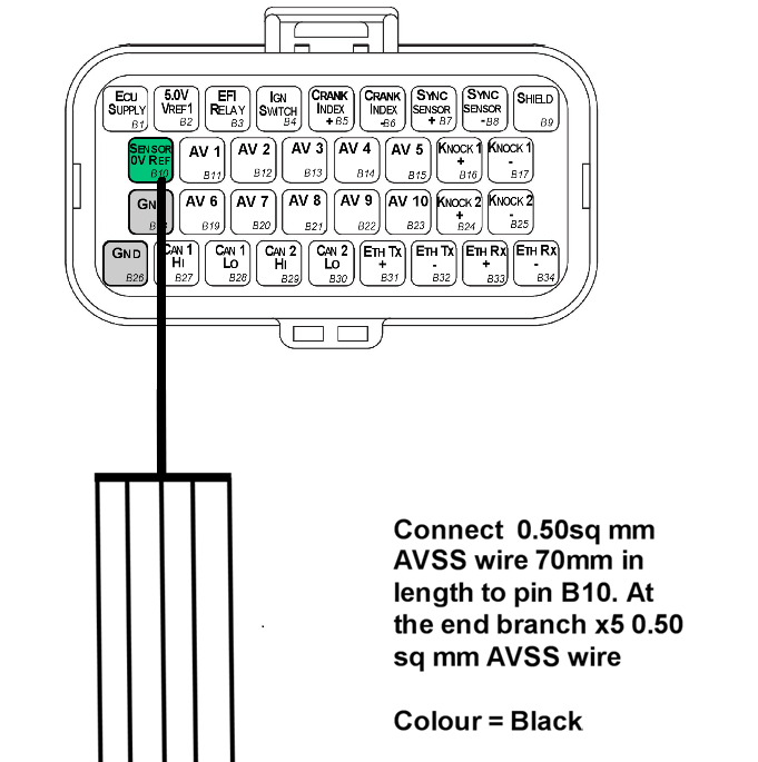
Pin B10 (Sensor Ground) is a branched connection feeding the analog sensor 0V references.
3.3 Pin B2 5V Supply Branched Connections
Pin B2 (5V Supply) is a branched connection feeding the engine sensor 5V supply.
3.4 Crank and Sync Shielded Cable Connections
- Use x1 2-core shielded cable for Pins B5 and B6
- Use x1 2-core shielded cable for Pins B7 and B8
NoteNOTE The individual core colours are not specified but there MUST be at least one different core colour between the Crank Index cable and Sync Sensor cable — i.e. the exact same cables cannot be used for both connections.
3.5 Knock Shielded Cable Connections
- Use x1 2-core shielded cable for Pins B16 and B17
- Use x1 2-core shielded cable for Pins B24 and B25
NoteNOTE The individual core colours are not specified but there MUST be at least one different core colour between the KNK 1 cable and KNK 2 cable — i.e. the exact same cables cannot be used for both connections. Ideally these core colours should also be different to those used in section 3.4.
3.6 Ethernet Sub Harness - Pins B31-B34
See the document “Ethernet to Superseal Loom Specification V1.x”. This sub harness should be plugged into Connector B, Pins B31 → B34.
Appendix A – SL8 ECU Pinout Drawing
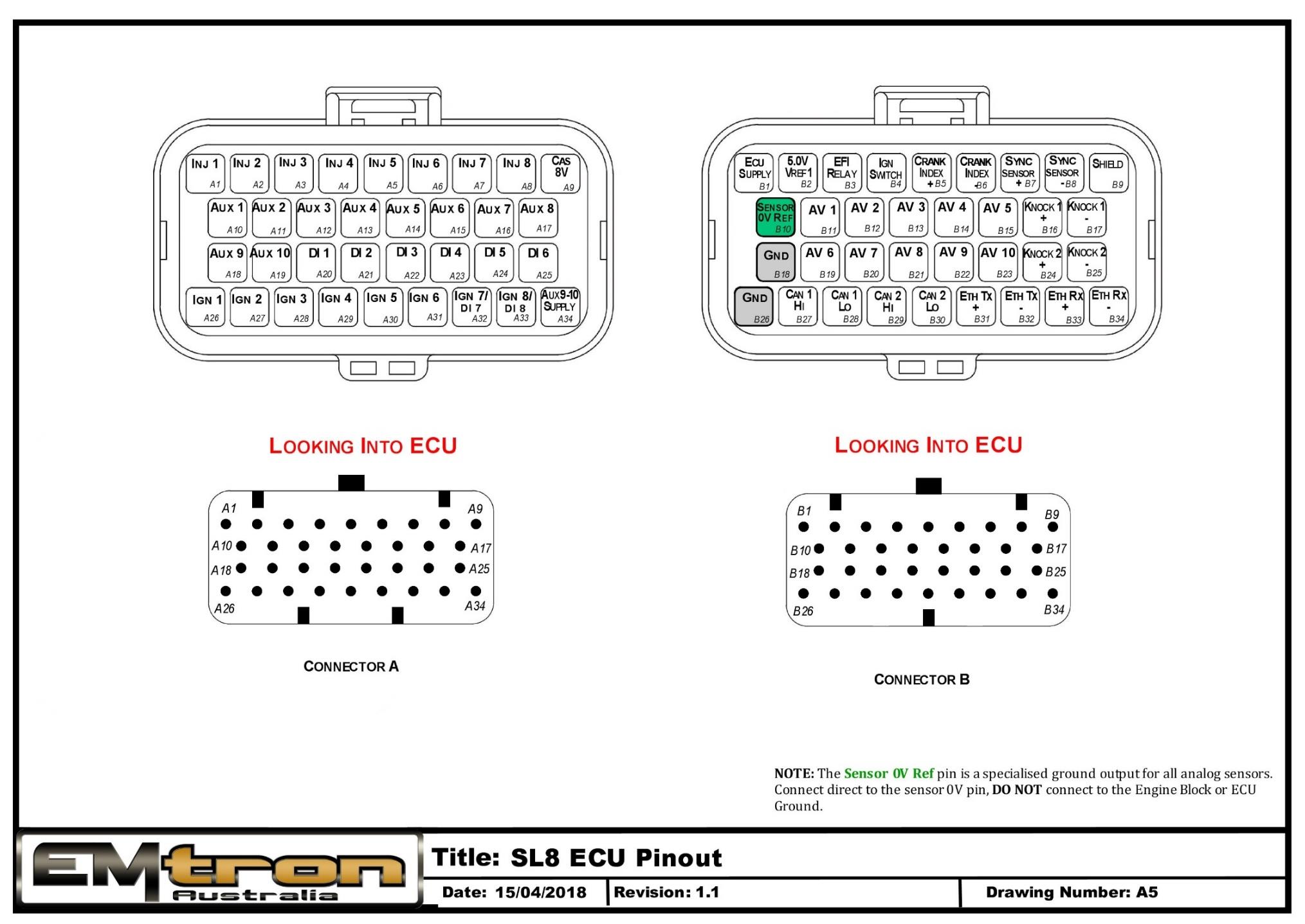
SL8 ECU pinout — Connector A and Connector B, looking into the ECU.
Appendix B – SL6 ECU Pinout Drawing
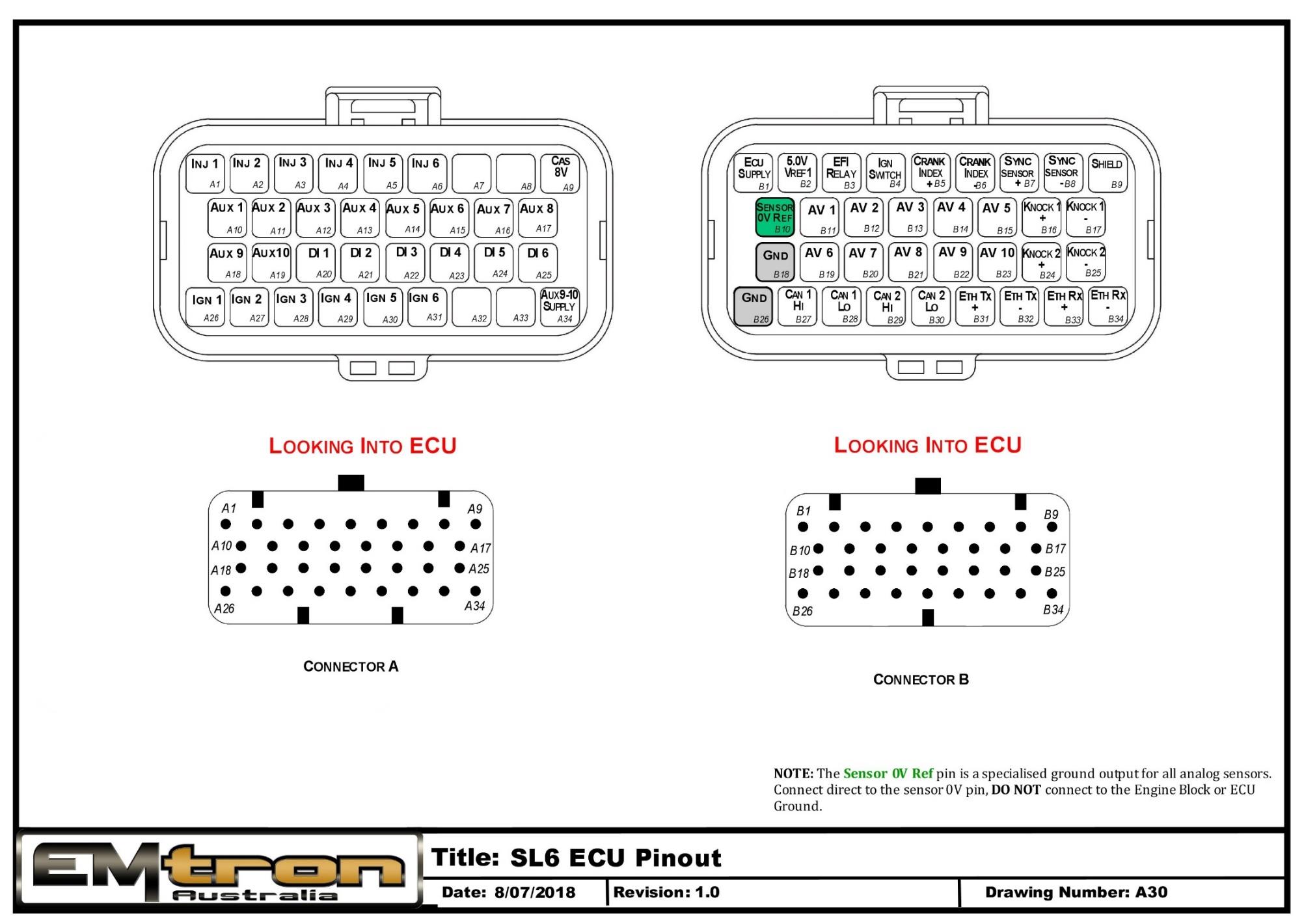
SL6 ECU pinout — Connector A and Connector B, looking into the ECU.
Appendix C – SL4 ECU Pinout Drawing
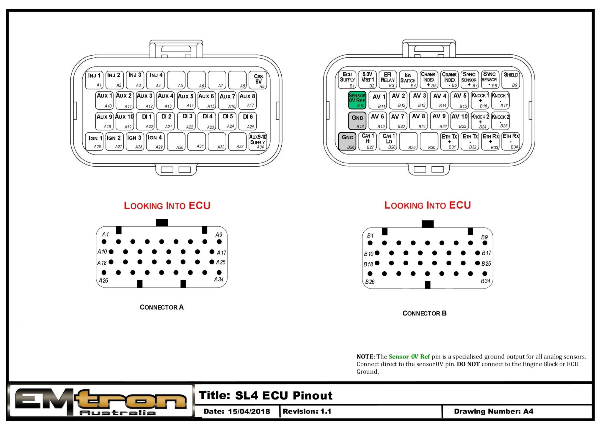
SL4 ECU pinout — Connector A and Connector B, looking into the ECU.
Appendix D – SL Series ECU Wiring
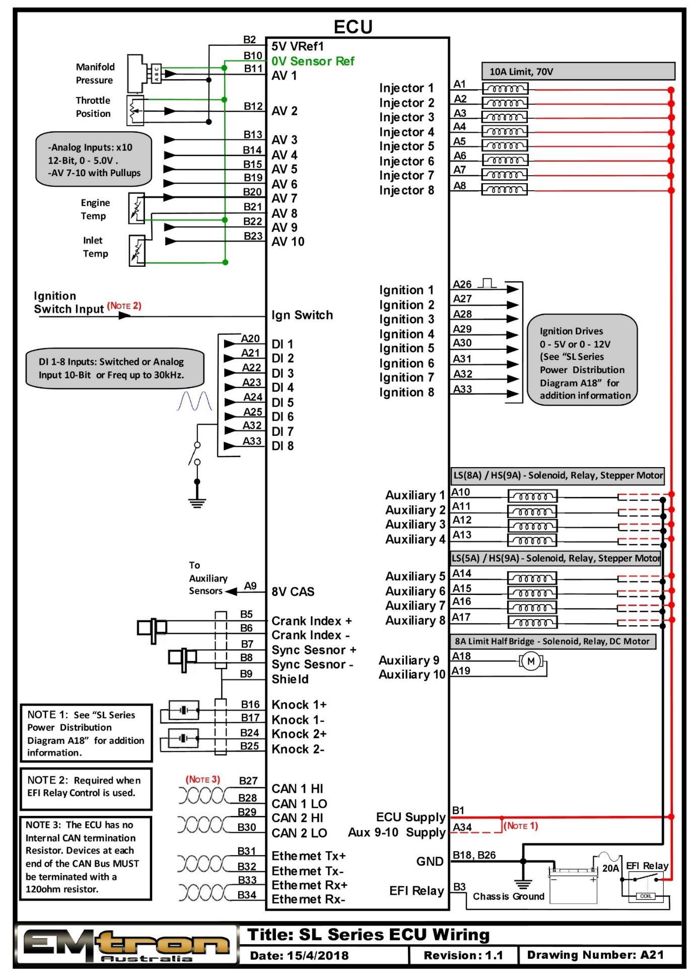
SL Series ECU wiring overview (drawing A21).
Appendix E – SL Series Ethernet Wiring
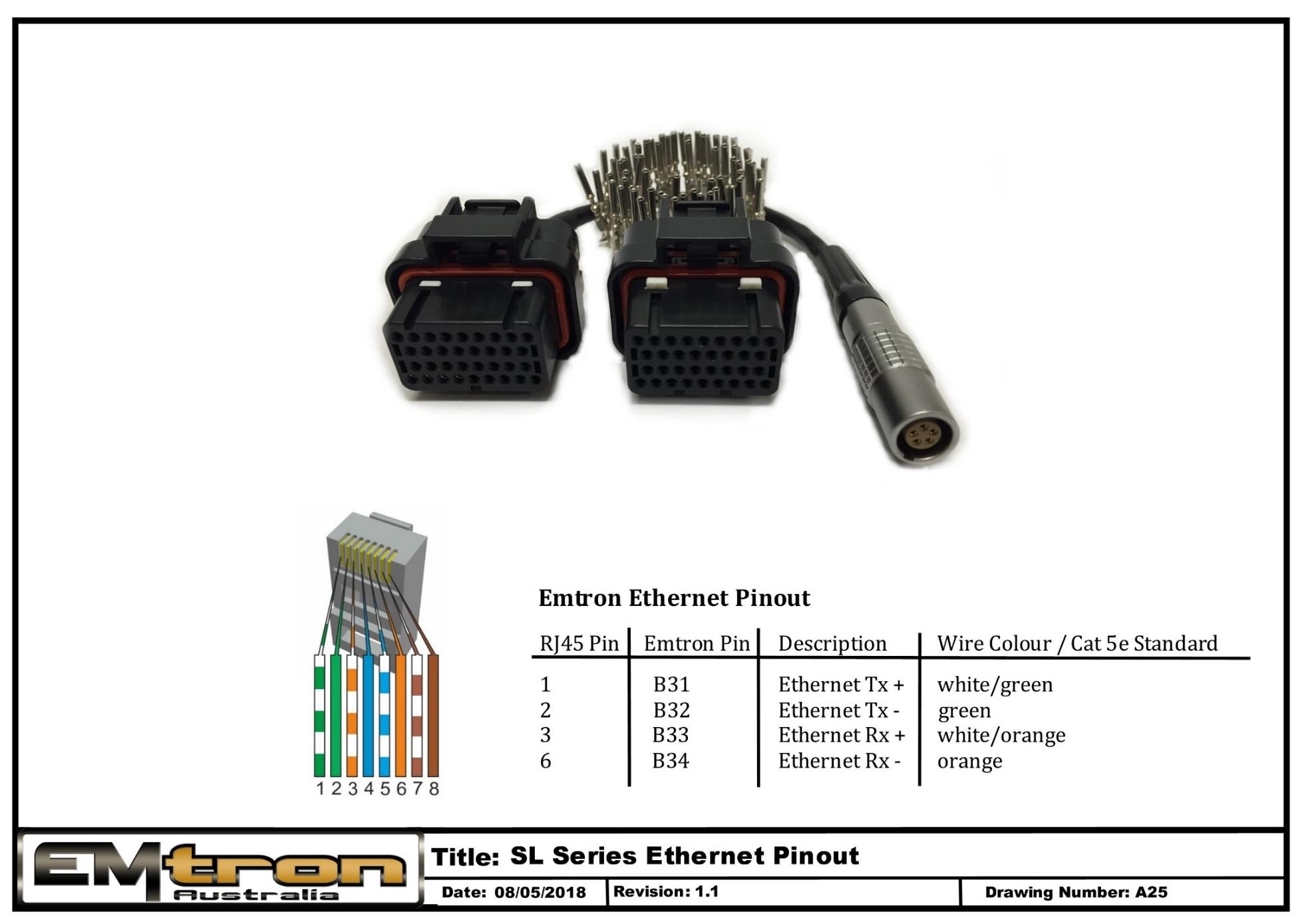
SL Series Ethernet wiring / tuning cable pinout (drawing A25).
SL Series Power Distribution Wiring
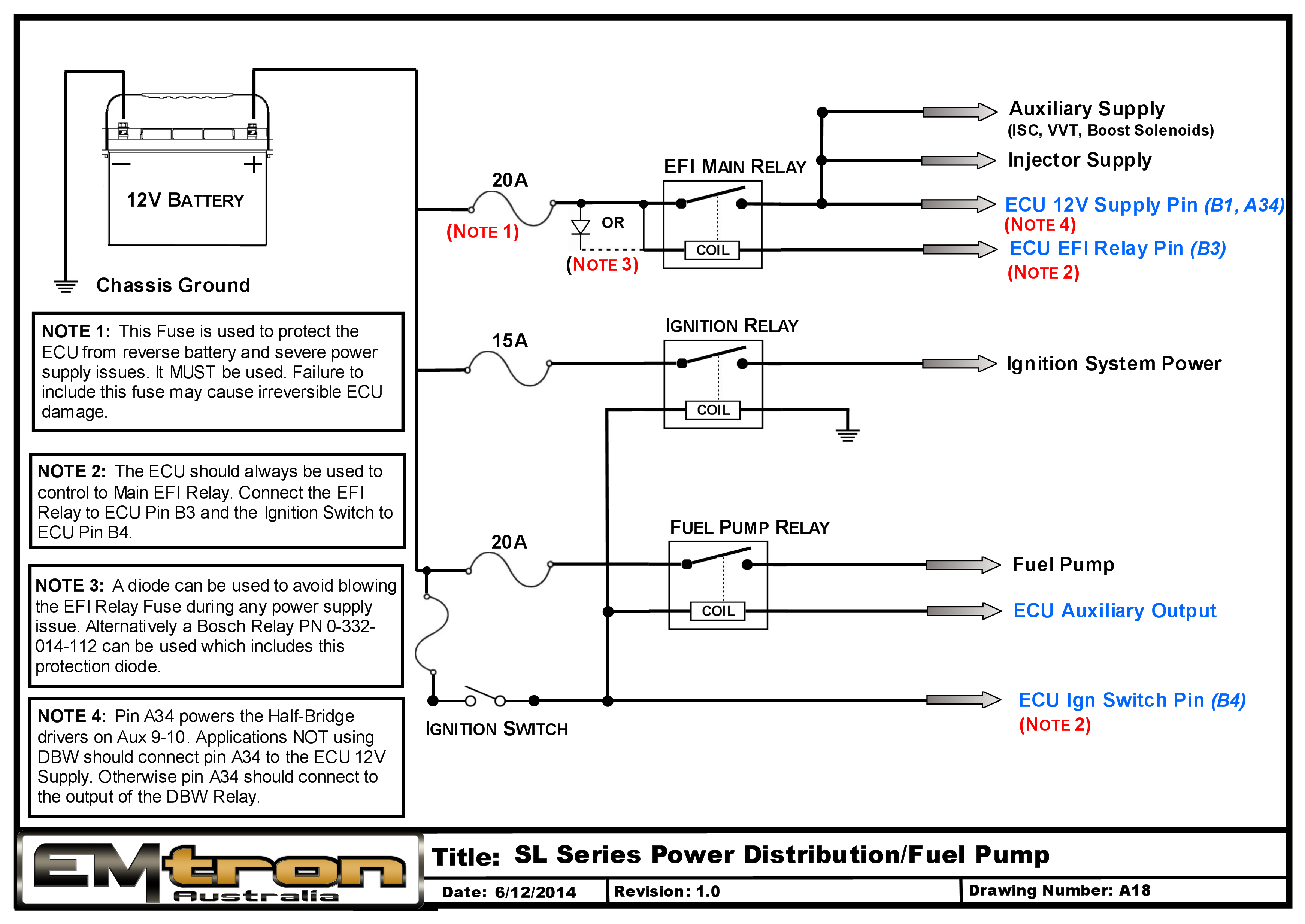
Shadow 8
Subsections of Shadow 8
Shadow 8 Pinout
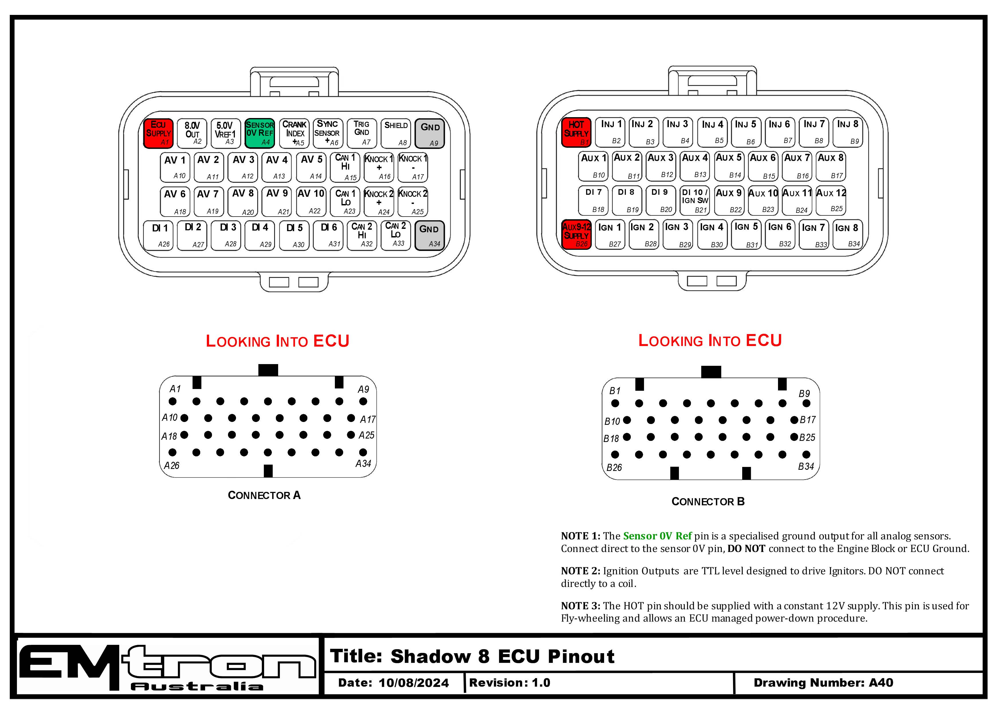
Shadow 8 ECU pinout — Connector A (signal/power) and Connector B (injection/ignition/aux), looking into the ECU connectors (drawing A40).
Connector A: Signal / Power / Communications / Triggers / Knock
(15.0A Max continuous current - wire gauge dependant)
| Pin | Channel Name | Pin | Channel Name |
|---|---|---|---|
| A1 | ECU Supply | A18 | Analog Voltage 6 |
| A2 | Sensor 8.0V Sensor Supply | A19 | Analog Voltage 7 |
| A3 | Sensor 5.0V Sensor Supply | A20 | Analog Voltage 8 |
| A4 | 0V Analog Reference | A21 | Analog Voltage 9 |
| A5 | Crank Position Sensor | A22 | Analog Voltage 10 |
| A6 | Sync Position Sensor | A23 | CAN Bus 1 Low |
| A7 | Trigger Ground | A24 | Knock 2 +ve |
| A8 | Shield | A25 | Knock 2 -ve |
| A9 | Ground 1 | A26 | Digital Input 1 |
| A10 | Analog Voltage 1 | A27 | Digital Input 2 |
| A11 | Analog Voltage 2 | A28 | Digital Input 3 |
| A12 | Analog Voltage 3 | A29 | Digital Input 4 |
| A13 | Analog Voltage 4 | A30 | Digital Input 5 |
| A14 | Analog Voltage 5 | A31 | Digital Input 6 |
| A15 | CAN Bus 1 High | A32 | CAN Bus 2 High |
| A16 | Knock 1 +ve | A33 | CAN Bus 2 Low |
| A17 | Knock 1 -ve | A34 | Ground 2 |
Connector B: Injection / Ignition / Auxiliary Outputs
(15.0A Max continuous current - wire gauge dependant)
| Pin | Channel Name | Pin | Channel Name |
|---|---|---|---|
| B1 | Battery Constant (HOT) Supply | B18 | Digital Input 7 |
| B2 | Injector Cylinder 1 | B19 | Digital Input 8 |
| B3 | Injector Cylinder 2 | B20 | Digital Input 9 |
| B4 | Injector Cylinder 3 | B21 | Digital Input 10 / Ignition Switch |
| B5 | Injector Cylinder 4 | B22 | Aux Output 9 |
| B6 | Injector Cylinder 5 | B23 | Aux Output 10 |
| B7 | Injector Cylinder 6 | B24 | Aux Output 11 |
| B8 | Injector Cylinder 7 | B25 | Aux Output 12 |
| B9 | Injector Cylinder 8 | B26 | Aux 9-12 Power Supply |
| B10 | Aux Output 1 | B27 | Ignition TTL Cylinder 1 |
| B11 | Aux Output 2 | B28 | Ignition TTL Cylinder 2 |
| B12 | Aux Output 3 | B29 | Ignition TTL Cylinder 3 |
| B13 | Aux Output 4 | B30 | Ignition TTL Cylinder 4 |
| B14 | Aux Output 5 | B31 | Ignition TTL Cylinder 5 |
| B15 | Aux Output 6 | B32 | Ignition TTL Cylinder 6 |
| B16 | Aux Output 7 | B33 | Ignition TTL Cylinder 7 |
| B17 | Aux Output 8 | B34 | Ignition TTL Cylinder 8 |
NoteNOTE 1 The Sensor 0V Ref pin (A4) is a specialised ground output for all analog sensors. Connect direct to the sensor 0V pin, DO NOT connect to the Engine Block or ECU Ground.
WarningNOTE 2 Ignition Outputs are TTL level designed to drive Ignitors. DO NOT connect directly to a coil.
ImportantNOTE 3 The HOT pin (B1) should be supplied with a constant 12V supply. This pin is used for fly-wheeling and allows an ECU managed power-down procedure.
Shadow 8 ECU Wiring
Shadow 8 Wiring Harness Specification
1.0 Introduction
This document contains the specification for the Emtron Shadow 8 ECU wiring harness.
- Loom Length = 2.5 meters
- Wire Type = AVSS
NoteNOTE Any unused pins MUST have blanking bungs fitted to the connector to keep the plug rated at its IP standard.
2.0 Connector A
| Property | Value |
|---|---|
| Name | Superseal |
| Manufacturer | TE |
| Description | 34 Way / Key 1 |
| Part Number | 4-1437290-0 |
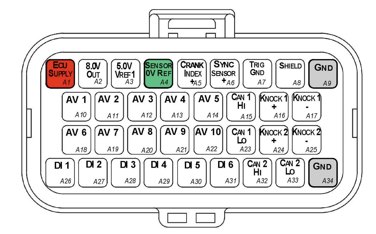
Connector A — TE Superseal 34 Way / Key 1.
2.1 Connector A Wire Colours
| Pin Name | Pin | Description | Colour | Wire Size (sq mm) |
|---|---|---|---|---|
| ECU SUPPLY | A1 | ECU Supply | Red | 0.85 |
| 8.0V OUT | A2 | 8V Cas Supply | Blue | 0.50 |
| 5.0V VREF1 | A3 | Main 5V engine sensor supply (Branched Cable) | Orange | 0.50 |
| SENSOR 0V REF | A4 | Sensor Ground (Branched Cable) | Black | 0.50 |
| CRANK INDEX + | A5 | Crank Index position sensor Positive | 2 core Shielded Cable (shared with A7) | — |
| SYNC SENSOR + | A6 | Sync Sensor Positive | 2 core Shielded Cable (shared with A7) | — |
| TRIG GND | A7 | Trigger Ground (Branched Cable, Black 70mm) | Black | 0.50 |
| SHIELD | A8 | Knock/Trigger Shield (White 70mm) | White | 0.50 |
| GND | A9 | Power Ground | Black | 0.85 |
| AV1 | A10 | Analog Voltage CH 1 | White | 0.50 |
| AV2 | A11 | Analog Voltage CH 2 | White | 0.50 |
| AV3 | A12 | Analog Voltage CH 3 | White | 0.50 |
| AV4 | A13 | Analog Voltage CH 4 | White | 0.50 |
| AV5 | A14 | Analog Voltage CH 5 | White | 0.50 |
| CAN 1 HI | A15 | Main Engine CAN | White | 0.50 |
| KNK 1 + | A16 | Knock Sensor 1 + | 2 core Shielded Cable (shared with A17) | — |
| KNK 1 - | A17 | Knock Sensor 1 - | 2 core Shielded Cable (shared with A16) | — |
| AV6 | A18 | Analog Voltage CH 6 | White | 0.50 |
| AV7 | A19 | Analog Voltage CH 7 | White | 0.50 |
| AV8 | A20 | Analog Voltage CH 8 | White | 0.50 |
| AV9 | A21 | Analog Voltage CH 9 | White | 0.50 |
| AV10 | A22 | Analog Voltage CH 10 | White | 0.50 |
| CAN 1 LO | A23 | Main Engine CAN | Green | 0.50 |
| KNK 2 + | A24 | Knock Sensor 2 + | 2 core Shielded Cable (shared with A25) | — |
| KNK 2 - | A25 | Knock Sensor 2 - | 2 core Shielded Cable (shared with A24) | — |
| DI 1 | A26 | Digital Input CH 1 | White | 0.50 |
| DI 2 | A27 | Digital Input CH 2 | White | 0.50 |
| DI 3 | A28 | Digital Input CH 3 | White | 0.50 |
| DI 4 | A29 | Digital Input CH 4 | White | 0.50 |
| DI 5 | A30 | Digital Input CH 5 | White | 0.50 |
| DI 6 | A31 | Digital Input CH 6 | White | 0.50 |
| CAN 2 HI | A32 | Auxiliary CAN | White | 0.50 |
| CAN 2 LO | A33 | Auxiliary CAN | Green | 0.50 |
| GND | A34 | Power Ground | Black | 0.85 |
3.0 Connector B
| Property | Value |
|---|---|
| Name | Superseal |
| Manufacturer | TE |
| Description | 34 Way / Key 2 |
| Part Number | 4-1437290-1 |
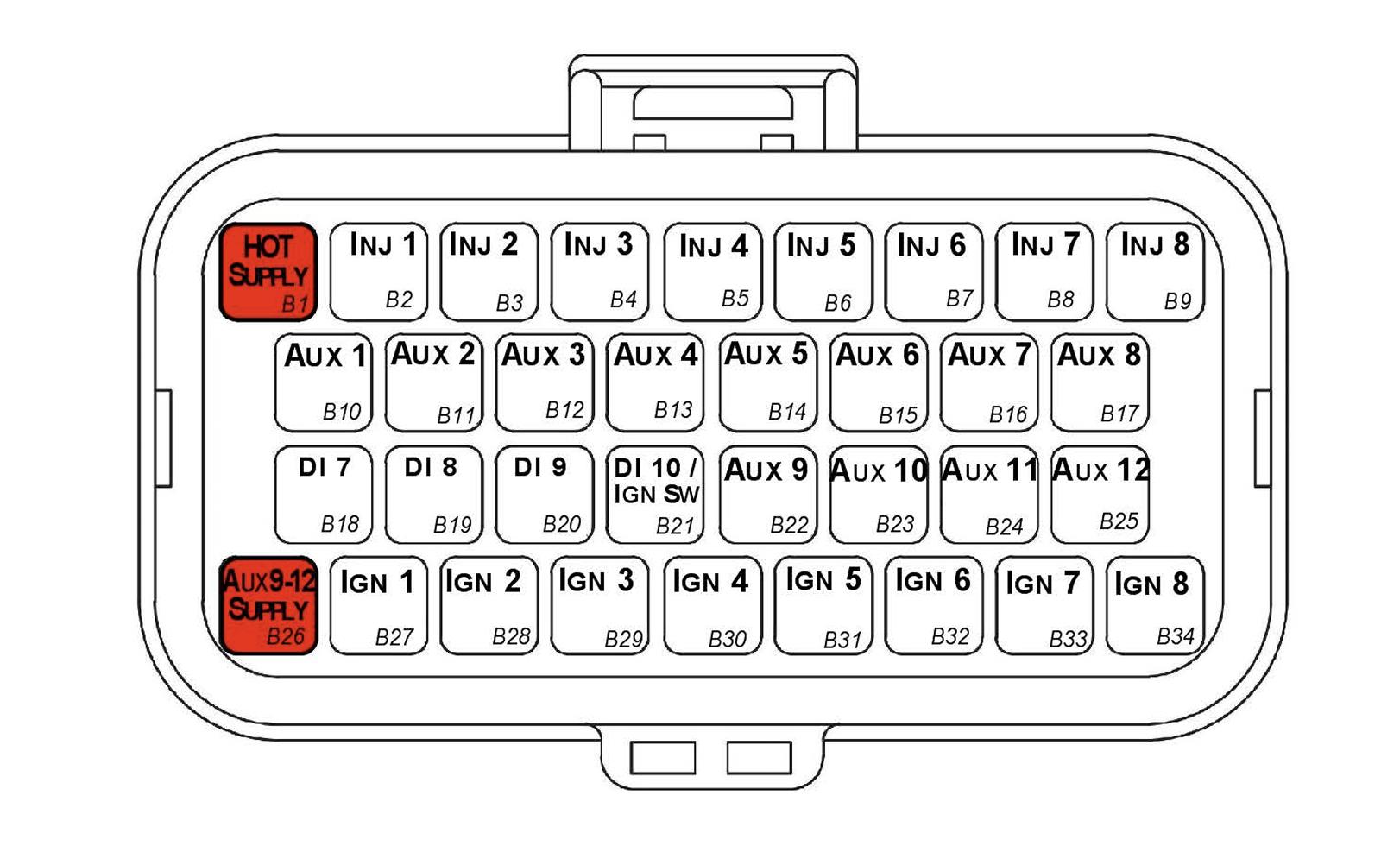
Connector B — TE Superseal 34 Way / Key 2.
3.1 Connector B Wire Colours
| Pin Name | Pin | Description | Colour | Wire Size (sq mm) |
|---|---|---|---|---|
| HOT SUPPLY | B1 | ECU +12V Constant | Red | 0.85 |
| INJ 1 | B2 | Injector Channel 1 | Blue | 0.50 |
| INJ 2 | B3 | Injector Channel 2 | Blue | 0.50 |
| INJ 3 | B4 | Injector Channel 3 | Blue | 0.50 |
| INJ 4 | B5 | Injector Channel 4 | Blue | 0.50 |
| INJ 5 | B6 | Injector Channel 5 | Blue | 0.50 |
| INJ 6 | B7 | Injector Channel 6 | Blue | 0.50 |
| INJ 7 | B8 | Injector Channel 7 | Blue | 0.50 |
| INJ 8 | B9 | Injector Channel 8 | Blue | 0.50 |
| AUX 1 | B10 | Auxiliary Channel 1 | Grey | 0.50 |
| AUX 2 | B11 | Auxiliary Channel 2 | Grey | 0.50 |
| AUX 3 | B12 | Auxiliary Channel 3 | Grey | 0.50 |
| AUX 4 | B13 | Auxiliary Channel 4 | Grey | 0.50 |
| AUX 5 | B14 | Auxiliary Channel 5 | Grey | 0.50 |
| AUX 6 | B15 | Auxiliary Channel 6 | Grey | 0.50 |
| AUX 7 | B16 | Auxiliary Channel 7 | Grey | 0.50 |
| AUX 8 | B17 | Auxiliary Channel 8 | Grey | 0.50 |
| DI 7 | B18 | Digital Input CH 7 | White | 0.50 |
| DI 8 | B19 | Digital Input CH 8 | White | 0.50 |
| DI 9 | B20 | Digital Input CH 9 | White | 0.50 |
| DI 10 / IGN SW | B21 | Digital Input CH 10 | White | 0.50 |
| AUX 9 | B22 | Auxiliary Channel 9 | Grey | 0.50 |
| AUX 10 | B23 | Auxiliary Channel 10 | Grey | 0.50 |
| AUX 11 | B24 | Auxiliary Channel 11 | Grey | 0.50 |
| AUX 12 | B25 | Auxiliary Channel 12 | Grey | 0.50 |
| AUX 9-12 SUPPLY | B26 | Aux 9-12 Supply | Red | 0.85 |
| IGN 1 | B27 | Ignition Channel 1 | Yellow | 0.50 |
| IGN 2 | B28 | Ignition Channel 2 | Yellow | 0.50 |
| IGN 3 | B29 | Ignition Channel 3 | Yellow | 0.50 |
| IGN 4 | B30 | Ignition Channel 4 | Yellow | 0.50 |
| IGN 5 | B31 | Ignition Channel 5 | Yellow | 0.50 |
| IGN 6 | B32 | Ignition Channel 6 | Yellow | 0.50 |
| IGN 7 | B33 | Ignition Channel 7 | Yellow | 0.50 |
| IGN 8 | B34 | Ignition Channel 8 | Yellow | 0.50 |
3.2 Pin A4 Sensor Ground Branched Connections
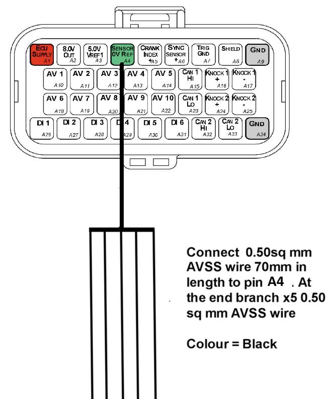
Pin A4 (Sensor 0V Ref) is a branched connection feeding the analog sensor 0V references.
3.3 Pin A3 5V Supply Branched Connections
Pin A3 (5.0V VRef1) is a branched connection feeding the engine sensor 5V supply.
3.4 Crank and Sync Shielded Cable Connections
- Use x1 2-core shielded cable for Pins A5 and A7 (Crank Index)
- Use x1 2-core shielded cable for Pins A6 and A7 (Sync Sensor)
NoteNOTE The individual core colours are not specified but there MUST be at least one different core colour between the Crank Index cable and Sync Sensor cable — i.e. the exact same cables cannot be used for both connections.
3.5 Knock Shielded Cable Connections
- Use x1 2-core shielded cable for Pins A16 and A17
- Use x1 2-core shielded cable for Pins A24 and A25
NoteNOTE The individual core colours are not specified but there MUST be at least one different core colour between the KNK 1 cable and KNK 2 cable — i.e. the exact same cables cannot be used for both connections. Ideally these core colours should also be different to those used in section 3.4.
Appendix A – Shadow 8 ECU Pinout Drawing
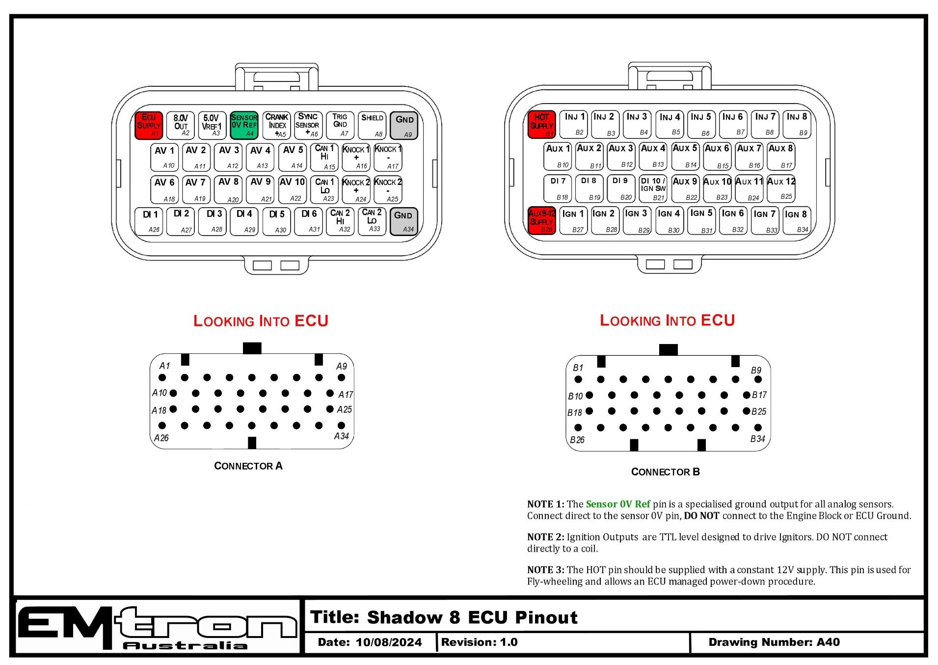
Shadow 8 ECU pinout — Connector A (signal/power) and Connector B (injection/ignition/aux), looking into the ECU (drawing A40).
Appendix B – Shadow Series ECU Wiring
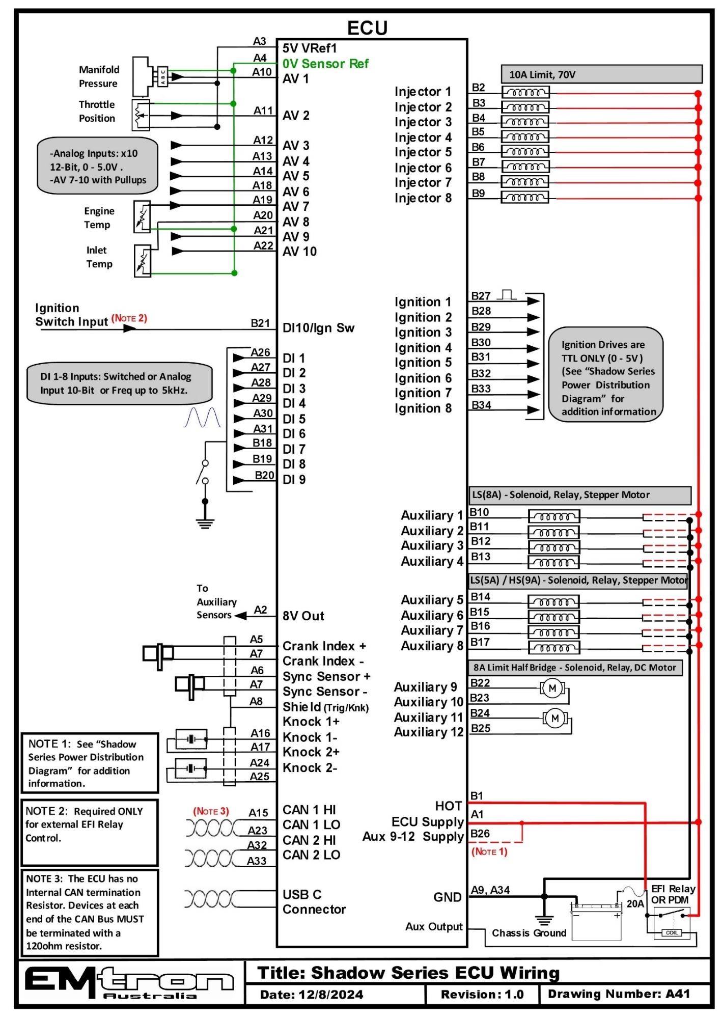
Shadow Series ECU wiring overview (drawing A41).
Shadow 8 Power Distribution Wiring
Shadow Power Supply System
The Shadow 8 power supply system has been designed to allow flexibility on how the ECU manages power-up and power-down sequencing.
The real advantage is on the power-down sequence, allowing the ECU to power-down once all pending tasks have been completed. This effectively acts as an internal Hold Power System.
ECU Supply (Pin A1)
Pin A1 is the main power supply into the ECU .
Battery Constant Supply (Pin B1)
ImportantPin B1 is a permanent power supply and should ALWAYS be connected to a constant 12V supply.ALL Auxiliary flywheel control is directed to the pin; therefore, this pin MUST always have power connected.
Note: The ECU draws zero current once completely shut down.
Aux 9-12 (Half Bridge) Driver Power Supply (Pin B26)
Pin B26 is a dedicated power supply for Auxiliary Channels 9-12. Power must be supplied to this pin for these channels to operate correctly.
In non-DBW (Drive by Wire) applications the ECU Supply can be shared, assuming the wire gauge has a sufficient rating for the current demand.
ImportantIn DBW applications power to this pin MUST come from an ECU controlled DBW Relay.ECU Power Supply Wiring
The ECU power supply can be configured in one of two ways; both options assume constant power is fed to pin B1.
OPTION A – Power Supply Pin Controlled
This is the main option for ECU Power Supply control.
Power-On
Power to the ECU Supply pin A1 can be switched ON using a PDM or from an Ignition switch controlled relay. When the ECU detects power on this pin, it will power up.
Power-Off
When the ECU Supply falls below 6.0V the ECU enters a Shutdown Sequence and uses the Constant Supply to remain ON during this process.
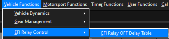
The ECU uses the time value from the “EFI Relay OFF table” to determine Power-down. However, the following tasks will prevent an ECU power-down:
- ECU CAL file Store in progress
- ECU Datalogging Store in progress
- Emtune connected. (Emtune must be disconnected for the ECU to power-down)
Once the ECU has completed all shut down tasks, and the EFI Relay OFF Delay time has elapsed, the ECU will power-down.
ECU Settings
The following settings must be configured for this mode to operate.
Ignition Switch Source Input selected to OFF

EFI Relay OFF Time
OPTION B – Ignition Switch Pin Controlled
This mode should only be used when the ECU needs to control an external EFI Relay, normally in OEM applications.
Power-On
This option uses the Ignition Switch Input, shared with DI10(Pin B21) to power-up the ECU.
When Ignition Switch Input Pin B21 is > 6.0V, the internal circuity will turn the ECU ON using the Battery Constant supply.
Once powered on, the ECU can switch/control an external OEM EFI relay using one of the ECU outputs.
For example, Aux 8 could be configured as a High Side Output, suppling power to a relay coil and turning it ON, which in turn supplies power to the ECU Pin A1.
Power-Off
When the Ignition Switch falls below 6.0V the ECU enters the Shutdown Sequence. The same shutdown conditions apply as outlined in Option A.
ECU Settings
The following settings must be configured for this mode to operate.
Ignition Switch Source Input selected to Dedicated – Ign -Sw. In this case this input is shared with DI10.

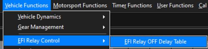
EFI Relay OFF Time
IMPORTANT NOTE
Regardless of the ECU’s settings, a high input on DI10 will cause the ECU to power up. Care should be taken to not unintentionally supply power to this pin.
Power Supply Wiring
EFI Relay Control
All Emtron ECU systems can control an EFI relay, allowing for management of its own power supply. To achieve this a dedicated Ignition Switch input and dedicated EFI Relay output are used. When 12V is applied to the Ignition Switch input, the ECUs fixed internal circuity switches the EFI Relay output to ground. This can be used to turn ON the Main relay and supply power to the ECU and sub systems. This functionality is controlled at a hardware level, meaning 12V at the Ignition Switch input will ALWAYS make the EFI Relay output turn ON and switch to ground.
Once powered up the ECU takes control of the EFI Relay output, operating independent of the Ignition Switch input. When the Ignition Switch input goes low (turns OFF) this triggers the ECU to enter shutdown mode, but the ECU will only switch the Main relay OFF after all critical self checks have been completed
WarningIt is highly recommended the EFI Relay system be used!By allowing the ECU to control its power supply, when the Ignition Switch input turns OFF the ECU can firstly complete critical tasks before shutting itself down (for example, DBW Self calibration and ECU Logging data storage).
The below image shows the internal operation of the EFI Relay system. The control on the EFI Relay output (Low side driver) is managed by a diode OR gate i.e if the Ignition Switch input is ON OR the ECU Control is ON, the EFI Relay output will be ON and providing a ground.
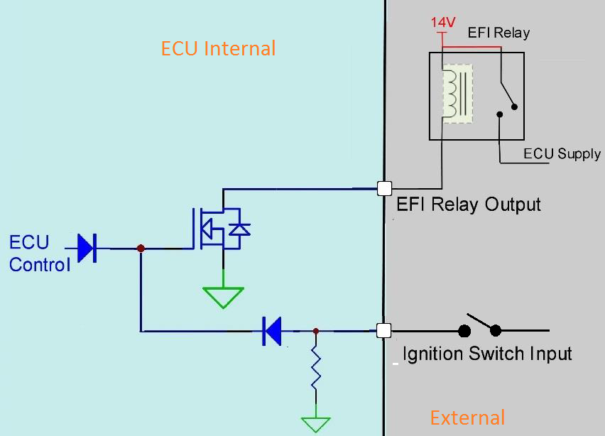
Dedicated EFI Relay Output
- Provides a relay ground, 200mA Limit.
- Short circuit, thermal overload protection, reverse battery.
KV Series: Pin D9. SL Series: Pin B3.
Dedicated Ignition Switch
- Used to control Main EFI Relay circuit at key-on.
- Input Analog Voltage Range: 0 - 20.0V.
- Input Impedance 100k Ohms to ground.
- Adjustable On/Off software thresholds. Resolution = 0.1V.
KV Series: Pin D15. SL Series: Pin B4.
Power Supply Input
The Emtron ECU system has a main power input to run the ECU (ECU supply pin), but also has the capability to distribute power through various outputs as well. The following power supply pins must be fed 12V in order for the ECU to distribute them to the following outputs (as high side outputs).
SL Series ECU
- Aux 5-8 ECU Supply Pin B1. As well as the main ECU supply, it also provides power to the Aux 5-8 High Side Drivers.
- Aux 9-10 Power Supply Pin A34. Supplies power to Aux 9/10 Half bridge drivers.
KV Series ECU
- Aux 1-8 ECU Supply Pin D1. As well as the main ECU supply, it also provides power to the Aux 1-8 High Side Drivers.
- Aux 9-12 Power Supply Pin D20. Supplies power to Aux 9/12 Half bridge drivers.
- Aux 13-16 Power Supply Input D2. Supplies power to Aux 13/16 Half bridge drivers.
H-Bridge control
Selected outputs can supply either a ground or battery voltage i.e. there is no “off” state, called Half-bridge outputs. Combine two half bridges and this forms an H-bridge configuration.Since the most common use for this type of output is Drive by Wire (DBW), it is necessary to control the supply power to these supply pins via a separate circuit so that the ECU can control this individually (E-throttle Relay Circuit).
This will allow the ECU to disconnect power to that distribution source in the event of an error being detected, but still maintain functionality of the engine, store fault codes, record logs, etc. Most DBW cars will default mechanical throttle position to a “raised” idle, and an extra level of Limp Mode will also function to cut RPM in the event of unintended mechanical acceleration.
SL Series ECU
- H-bridge control for Aux 9-10 (1 pair).
KV8/12 ECU
- H-bridge control for Aux 9-10 / Aux 11-12 (2 pair).
KV16/16M ECU
- H-bridge control for Aux 9-10 / Aux 11-12 / Aux 13-14 / Aux 15-16 (4 pair).
Grounds
Main ECU Grounds
All Emtron grounds are internally linked, however each ECU major section/plug has dedicated grounds. Most ECU functions in general distribute ground connection to operate components (fuel injectors, relays, boost solenoids, etc). Do NOT try to use one single ground since they are all linked. Pay mind to the fact that all of these outputs need to make complete circuits to ground when being activated, and the current limit of each ECU pin is only 12 amps.
Sensor 0V Reference Grounds
These pins are NOT ECU grounds. Although a multi-meter test will show continuity to the ECU ground, these pins are designed as a low current 0V reference for pressure, position and temperature sensors. The following rules MUST always be observed:
WarningDO NOT connect these pins to the ECU main ground location(s)!This is a specialized ground reference for all analog sensors and should be connected directly to the sensor 0V(ground) pin.
WarningDO NOT connect frequency-based sensor grounds to the 0V Reference pin.For example: an Ethanol content sensor. Use the main ECU ground.
Differential Input Grounds
Inputs with +/- (Crank, Sync, Knock) are considered Differential Inputs. These “-” pins are used for as a comparator for the input pin, and are NOT linked to ECU grounds or Sensor 0V Reference grounds (regardless of tested continuity). This is also the reason pulsed signals are safe to be connected to these pins. When wiring these inputs, it is highly recommended to use them without fail, as like the 0V reference for analog volt sensors, the differential input will behave appropriately during all electrical situations such as when voltage drop can be high during cranking, etc.