KV16 Pinout Rev2
Pin Descriptions
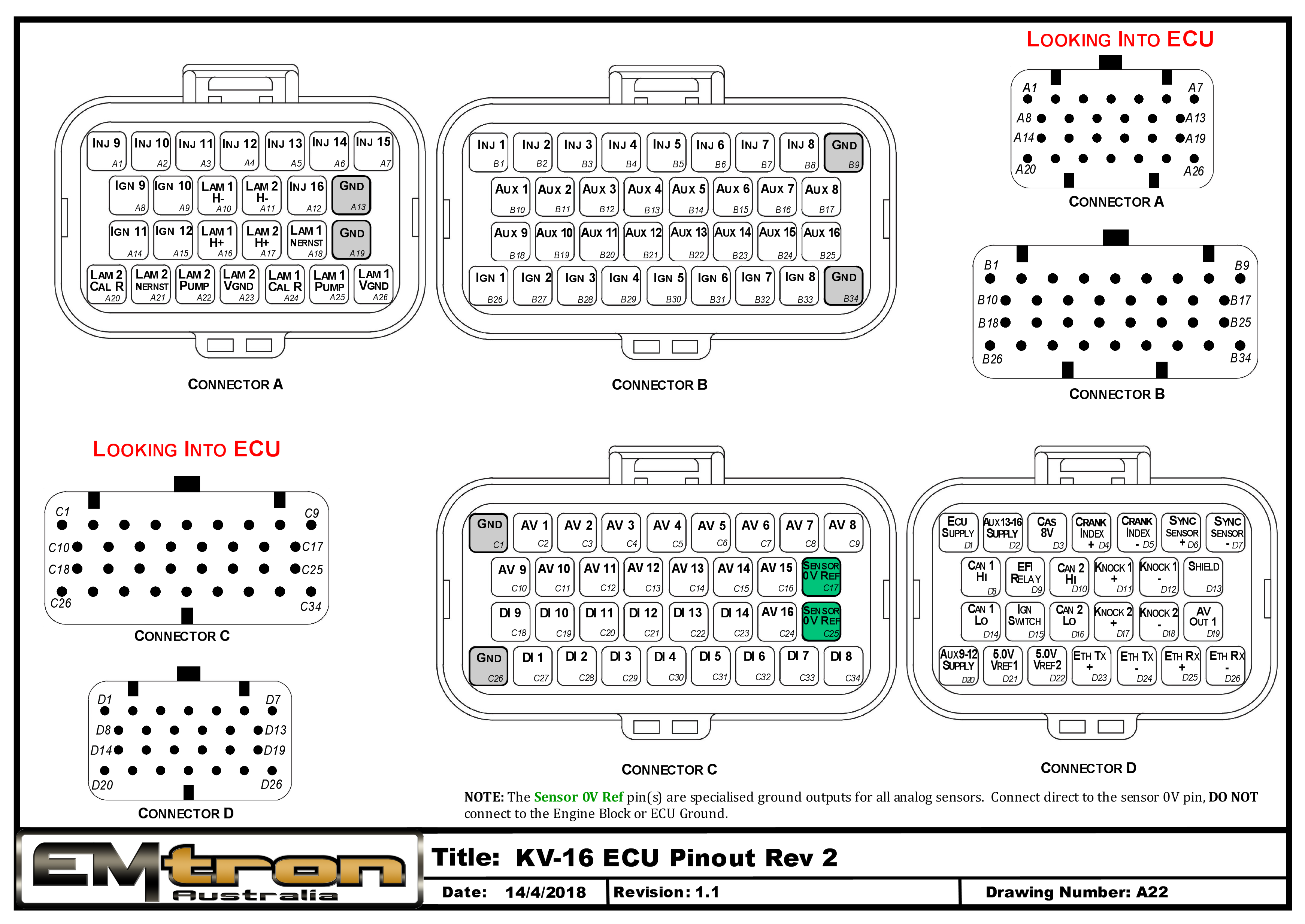
| Connector A: Lambda/Injection/Ignition (15.0A Max continuous current - wire gauge dependant) |
|---|
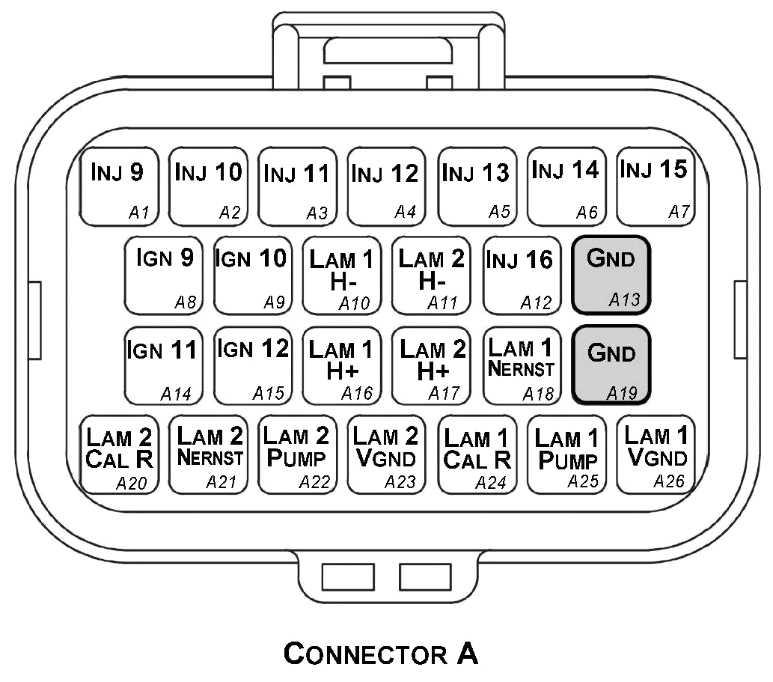
Looking into ECU connector
| Pin | Channel Name |
|---|---|
| A1 | Injection Channel 9 |
| A2 | Injection Channel 10 |
| A3 | Injection Channel 11 |
| A4 | Injection Channel 12 |
| A5 | Injection Channel 13 |
| A6 | Injection Channel 14 |
| A7 | Injection Channel 15 |
| A8 | Ignition Channel 9 |
| A9 | Ignition Channel 10 |
| A10 | Lambda 1 Heater - |
| A11 | Lambda 2 Heater - |
| A12 | Injection Channel 16 |
| A13 | ECU Ground |
| A14 | Ignition Channel 11 |
| A15 | Ignition Channel 12 |
| A16 | Lambda 1 Heater + |
| A17 | Lambda 2 Heater + |
| A18 | Lambda 1 Nernst Cell (Vs) |
| A19 | ECU Ground |
| A20 | Lambda 2 Cal Resistor (CalR) |
| A21 | Lambda 2 Nernst Cell (Vs) |
| A22 | Lambda 2 Pump Cell (Ip) |
| A23 | Lambda 2 Virtual Ground (VGnd) |
| A24 | Lambda 1 Cal Resistor (CalR) |
| A25 | Lambda 1 Pump Cell (Ip) |
| A26 | Lambda 1 Virtual Ground (VGnd) |
| Connector B: Auxiliary Outputs /Fuel/Ignition/Ground (15.0A Max continuous current - wire gauge dependant) |
|---|
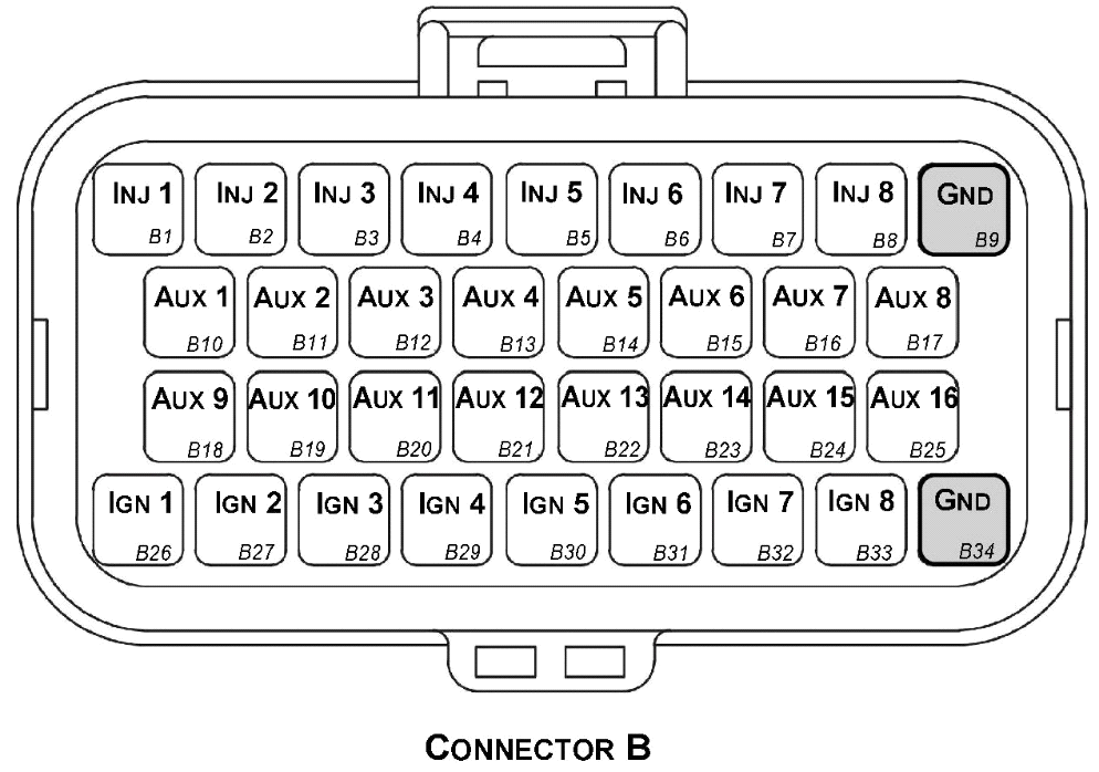
Looking into ECU connector
| Pin | Channel Name | Pin | Channel Name |
|---|---|---|---|
| B1 | Injection Channel 1 | B18 | Auxiliary Output 9 |
| B2 | Injection Channel 2 | B19 | Auxiliary Output 10 |
| B3 | Injection Channel 3 | B20 | Auxiliary Output 11 |
| B4 | Injection Channel 4 | B21 | Auxiliary Output 12 |
| B5 | Injection Channel 5 | B22 | Auxiliary Output 13 |
| B6 | Injection Channel 6 | B23 | Auxiliary Output 14 |
| B7 | Injection Channel 7 | B24 | Auxiliary Output 15 |
| B8 | Injection Channel 8 | B25 | Auxiliary Output 16 |
| B9 | ECU Ground | B26 | Ignition Channel 1 |
| B10 | Auxiliary Output 1 | B27 | Ignition Channel 2 |
| B11 | Auxiliary Output 2 | B28 | Ignition Channel 3 |
| B12 | Auxiliary Output 3 | B29 | Ignition Channel 4 |
| B13 | Auxiliary Output 4 | B30 | Ignition Channel 5 |
| B14 | Auxiliary Output 5 | B31 | Ignition Channel 6 |
| B15 | Auxiliary Output 6 | B32 | Ignition Channel 7 |
| B16 | Auxiliary Output 7 | B33 | Ignition Channel 8 |
| B17 | Auxiliary Output 8 | B34 | ECU Ground |
| Connector C: Signal (15.0A Max continuous current - wire gauge dependant) |
|---|
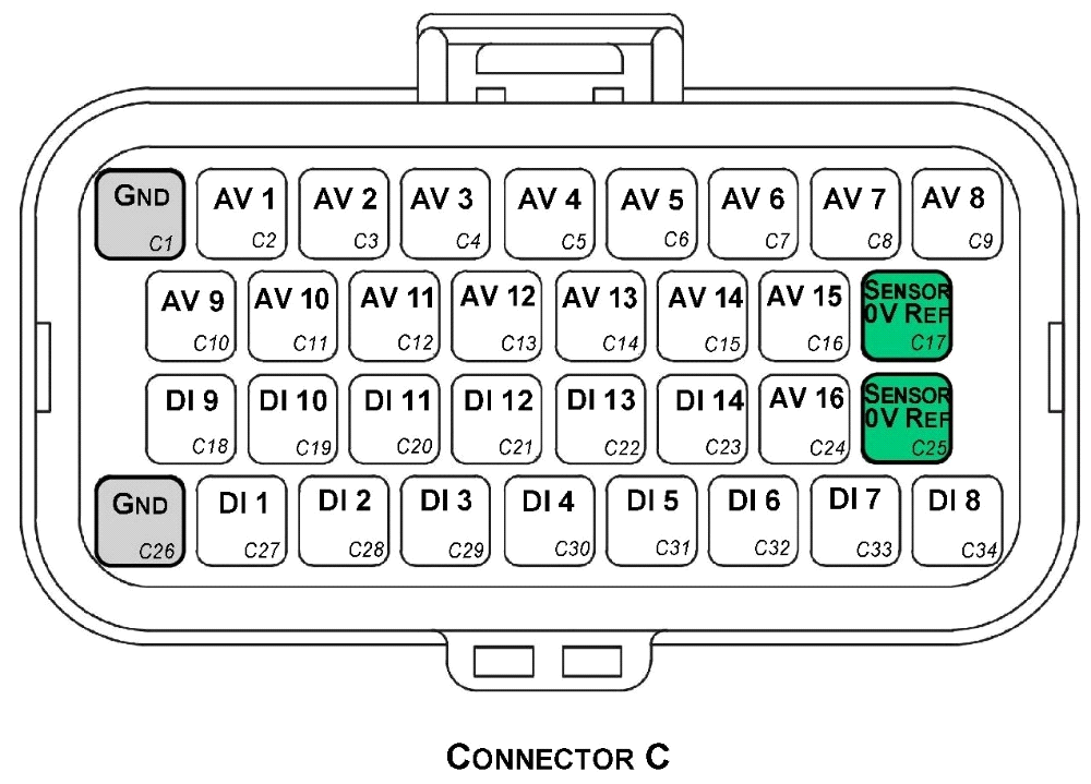
Looking into ECU connector
| Pin | Channel Name | Pin | Channel Name |
|---|---|---|---|
| C1 | ECU Ground | C18 | Digital Input 9 |
| C2 | Analog Input Channel 1 | C19 | Digital Input 10 |
| C3 | Analog Input Channel 2 | C20 | Digital Input 11 |
| C4 | Analog Input Channel 3 | C21 | Digital Input 12 |
| C5 | Analog Input Channel 4 | C22 | Digital Input 13 |
| C6 | Analog Input Channel 5 | C23 | Digital Input 14 |
| C7 | Analog Input Channel 6 | C24 | Analog Input Channel 16 |
| C8 | Analog Input Channel 7 | C25 | Analog Sensor 0V Reference |
| C9 | Analog Input Channel 8 | C26 | ECU Ground |
| C10 | Analog Input Channel 9 | C27 | Digital Input 1 |
| C11 | Analog Input Channel 10 | C28 | Digital Input 2 |
| C12 | Analog Input Channel 11 | C29 | Digital Input 3 |
| C13 | Analog Input Channel 12 | C30 | Digital Input 4 |
| C14 | Analog Input Channel 13 | C31 | Digital Input 5 |
| C15 | Analog Input Channel 14 | C32 | Digital Input 6 |
| C16 | Analog Input Channel 15 | C33 | Digital Input 7 |
| C17 | Analog Sensor 0V Reference | C34 | Digital Input 8 |
| Connector D: Power/Communications/Triggers/Knock (15.0A Max continuous current - wire gauge dependant) |
|---|
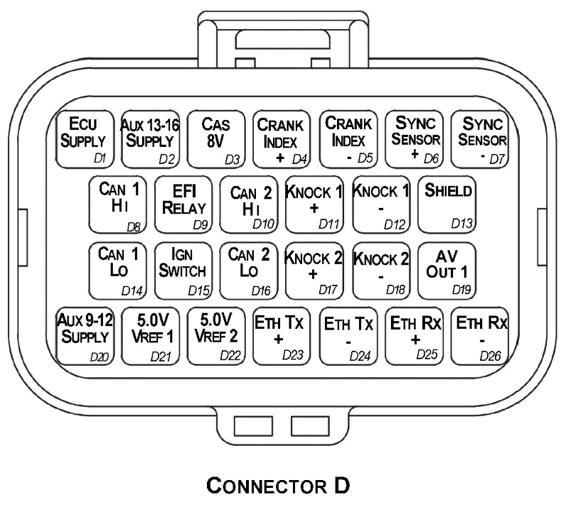
Looking into ECU connector
| Pin | Channel Name |
|---|---|
| D1 | ECU 14V Supply |
| D2 | Auxiliary Output 13-16 14V Supply |
| D3 | Sensor Supply 8V |
| D4 | Crank Index Sensor + |
| D5 | Crank Index Sensor - |
| D6 | Sync Sensor + |
| D7 | Sync Sensor - |
| D8 | CAN 1H |
| D9 | EFI Relay Output (Low Side 200mA) |
| D10 | CAN 2H |
| D11 | Knock 1 + |
| D12 | Knock 1 - |
| D13 | Shield (Crank/Cam/ Knock) |
| D14 | CAN 1L |
| D15 | Ignition Switch Input |
| D16 | CAN 2L |
| D17 | Knock 2 + |
| D18 | Knock 2 - |
| D19 | Analog Output (0.0 - 5.0V) |
| D20 | Auxiliary Output 9-12 14V Supply |
| D21 | Sensor Supply Vref1: 5.0V |
| D22 | Sensor Supply Vref2: 5.0V |
| D23 | Ethernet Tx + |
| D24 | Ethernet Tx - |
| D25 | Ethernet Rx + |
| D26 | Ethernet Rx - |
Important Notes
Auxiliary Output Channels 13-16
These are high current Half bridge drivers which switch either to ground or 14V i.e. they do not have a high impedance or OFF state. When the ECU is powered OFF these Auxiliary Channels by default will be switching to ground. This means:
- Solenoids or relays connected to these outputs should not use a constant or hot battery feed.
- During the ECU powerup sequence, any solenoid or relay connected to these outputs should have a managed power feed to avoid momentary switching during powerup.
Analog Sensor 0V Reference (Pin C17, C25)
These pins should be connected directly to the 0V (Ground) pin on any low current analog sensor, for example Pressure or Temperature.
- DO NOT connect the ECU pins C17, C25 directly to the Engine Block or ECU Ground. These are dedicated and specialised ground outputs for all analog channels and should be connected directly to the sensor.
- DO NOT connect frequency-based sensors to these pins; for example, an Ethanol content sensor. The sensor 0V pin should be connected to the ECU ground.
Half Bridge Driver Power Supply Inputs (Pin D20, D2)
Pin D20 is a dedicated power supply for Auxiliary Channels 9-12. Power must be supplied to this pin for these channels to operate correctly. In non-DBW (Drive by Wire) applications the ECU Supply power can be shared, assuming the wire gauge has a sufficient rating for the current demand. In DBW applications power to this pin MUST come from an ECU controlled DBW Relay.
Pin D2 is a dedicated power supply for Auxiliary Channels 13-16. Power must be supplied to this pin for these Auxiliary channels to operate correctly.