KV16M Pinout
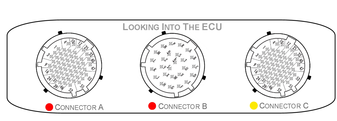
| Mating Connectors Loom Side (Deutsch Autosport AS Series; S = Socket#8202;) |
|---|
| Mating connector A AS616-35SN (Red) |
| Mating connector B AS616-26SN (Red) |
| Mating connector C AS616-35SA (Yellow) |
| Connector A: Injection/Ignition/Digital Inputs. (5.0A continuous current. Shell size 16, 55 Pin. 22 AWG) |
|---|
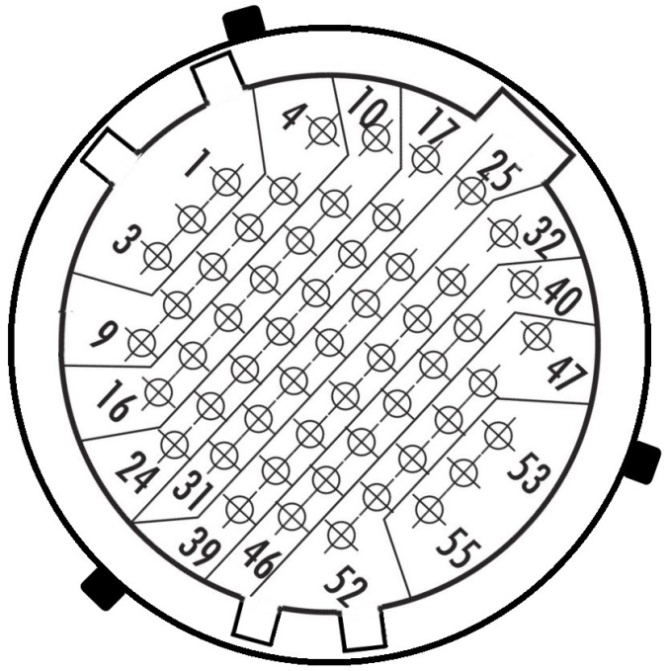
**Looking into ECU Connector**
| Pin | Channel Name | Pin | Channel Name |
|---|---|---|---|
| 1 | Injection Channel 1 | 29 | Lambda 2 Heater + |
| 2 | Injection Channel 2 | 30 | Lambda 2 Heater - |
| 3 | Injection Channel 3 | 31 | Digital Input Ground Out |
| 4 | Injection Channel 4 | 32 | Ignition Channel 1 |
| 5 | Injection Channel 5 | 33 | Ignition Channel 2 |
| 6 | Injection Channel 6 | 34 | Ignition Channel 3 |
| 7 | Injection Channel 7 | 35 | Ignition Channel 4 |
| 8 | Injection Channel 8 | 36 | Ignition Channel 5 |
| 9 | Injection Channel 9 | 37 | Ignition Channel 6 |
| 10 | Injection Channel 10 | 38 | Ignition Channel 7 |
| 11 | Injection Channel 11 | 39 | Ignition Channel 8 |
| 12 | Injection Channel 12 | 40 | Ignition Channel 9 |
| 13 | Injection Channel 13 | 41 | Ignition Channel 10 |
| 14 | Injection Channel 14 | 42 | Ignition Channel 11 |
| 15 | Injection Channel 15 | 43 | Ignition Channel 12 |
| 16 | Injection Channel 16 | 44 | Digital Input 3 |
| 17 | Lambda 1 Nernst Cell (Vs) | 45 | Digital Input 2 |
| 18 | Lambda 1 Cal Resistor (CalR) | 46 | Digital Input 1 |
| 19 | Lambda 1 Pump Cell (Ip) | 47 | Digital Input 9 |
| 20 | Lambda 1 Virtual Ground (VGnd) | 48 | Digital Input 8 |
| 21 | Lambda 1 Heater + | 49 | Digital Input 7 |
| 22 | Lambda 1 Heater - | 50 | Digital Input 6 |
| 23 | Digital Input 13 | 51 | Digital Input 5 |
| 24 | Digital Input 14 | 52 | Digital Input 4 |
| 25 | Lambda 2 Pump Cell (Ip) | 53 | Digital Input 10 |
| 26 | Lambda 2 Virtual Ground (VGnd) | 54 | Digital Input 11 |
| 27 | Lambda 2 Nernst Cell (Vs) | 55 | Digital Input 12 |
| 28 | Lambda 2 Cal Resistor (CalR) |
| Connector B: Power/Ground/Auxiliary Outputs (7.5A continuous current. Shell size 16, 26 Pin. 20 AWG) |
|---|
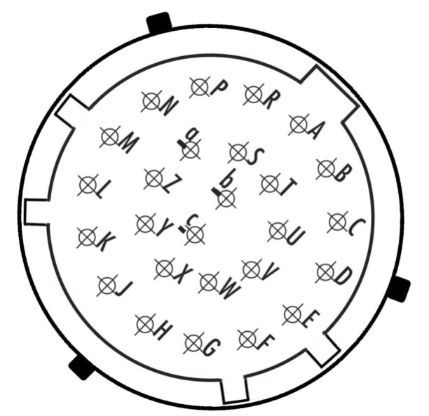
Looking into ECU Connector
| Pin | Channel Name |
|---|---|
| A | ECU 14V Supply |
| B | ECU 14V Supply |
| C | ECU 14V Supply |
| D | ECU Ground |
| E | ECU Ground |
| F | Auxiliary Output 16 |
| G | Auxiliary Output 15 |
| H | Auxiliary Output 14 |
| J | Auxiliary Output 12 |
| K | Auxiliary Output 10 |
| L | Auxiliary Output 8 |
| M | Auxiliary Output 7 |
| N | Auxiliary Output 5 |
| P | Auxiliary Output 3 |
| R | Auxiliary Output 1 |
| S | Auxiliary Output 2 |
| T | ECU 14V Supply |
| U | ECU Ground |
| V | ECU Ground |
| W | Auxiliary Output 13 |
| X | Auxiliary Output 11 |
| Y | Auxiliary Output 9 |
| Z | Auxiliary Output 6 |
| a | Auxiliary Output 4 |
| b | ECU Ground |
| c | ECU Ground |
| Connector: C Signal. (5.0A continuous current. Shell size 16, 55 Pin. 22 AWG) |
|---|
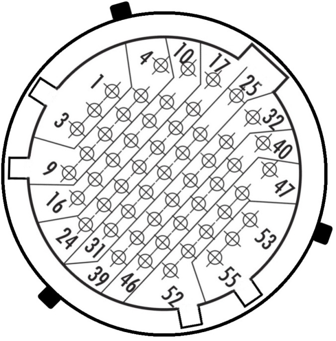
**Looking into ECU Connector**
| Pin | Channel Name | Pin | Channel Name |
|---|---|---|---|
| 1 | Analog Input Channel 1 | 29 | Analog Sensor 0V Reference |
| 2 | Analog Input Channel 2 | 30 | Analog Sensor 0V Reference |
| 3 | Analog Input Channel 3 | 31 | Analog Sensor 0V Reference |
| 4 | Analog Input Channel 4 | 32 | Knock 2 + |
| 5 | Analog Input Channel 5 | 33 | Analog Out |
| 6 | Analog Input Channel 6 | 34 | CAN 2L |
| 7 | Analog Input Channel 7 | 35 | CAN 2H |
| 8 | Analog Input Channel 8 | 36 | CAN 1L |
| 9 | Analog Input Channel 9 | 37 | CAN 1H |
| 10 | Analog Input Channel 10 | 38 | Sensor Supply Vref2: 5.0V |
| 11 | Analog Input Channel 11 | 39 | Sensor Supply Vref2: 5.0V |
| 12 | Analog Input Channel 12 | 40 | Knock 1 - |
| 13 | Analog Input Channel 13 | 41 | Sync Sensor - |
| 14 | Analog Input Channel 14 | 42 | Sync Sensor + |
| 15 | Analog Input Channel 15 | 43 | Crank Index Sensor - |
| 16 | Analog Input Channel 16 | 44 | Crank Index Sensor + |
| 17 | Analog Input Channel 17 | 45 | Sensor Supply Vref1: 5.0V |
| 18 | Analog Input Channel 18 | 46 | Sensor Supply Vref1: 5.0V |
| 19 | Analog Input Channel 19 | 47 | Knock 1 + |
| 20 | Analog Input Channel 20 | 48 | Ethernet Tx + |
| 21 | Analog Input Channel 21 | 49 | Ethernet Tx - |
| 22 | Analog Input Channel 22 | 50 | Ethernet Rx + |
| 23 | Analog Input Channel 23 | 51 | Ethernet Rx - |
| 24 | Analog Input Channel 24 | 52 | Sensor Supply 8V |
| 25 | Knock 2 - | 53 | Constant 14V Supply(Backup) |
| 26 | SHIELD (Crank/Cam/ Knock) | 54 | Sensor Supply Vref3: 5.0V |
| 27 | SHIELD (Crank/Cam/ Knock) | 55 | Sensor Supply Vref3: 5.0V |
| 28 | Analog Sensor 0V Reference |
Important Notes
Auxiliary Output Channels 13-16
These are high current Half bridge drivers which switch either to ground or 14V i.e. they do not have a high impedance or OFF state. When the ECU is powered OFF these Auxiliary Channels by default will be switching to ground. This means:
- Solenoids or relays connected to these outputs should not use a constant or hot battery feed.
- During the ECU powerup sequence, any solenoid or relay connected to these outputs should have a managed power feed to avoid momentary switching during powerup.
Constant 14V Supply/Backup (Pin C53)
This pin has two features:
1) Flywheeling for Auxiliary Channels 1-8. Any Inductive energy will be sent to the “Constant 14V Supply” pin. To minimise any EMI and allow solenoid current recirculation to operate correctly this pin should be connected to a constant power supply. If this pin is left unconnected the back EMF will be clamped at 45V.
2) Internal ECU EFI Relay function. When power is removed from pins " ECU 14V Supply" the ECU automatically switches to the “Constant 14V Supply” to keep the ECU powered. This will allow the ECU to complete critical tasks before shutting itself down (for example, DBW Self calibration and ECU Logging data storage).
To enable this function, set the EFI Relay Control Channel to “Internal EFI Relay Ctrl”
NOTE: With a Constant 14V supply wired, the ECU draws no additional current when OFF.
Analog Sensor 0V Reference (Pin C28, C29, C30, C31)
As the name indicates these should be connected directly to the 0V (Ground) pin on any low current analog sensor, for example Pressure or Temperature.
- DO NOT connect these pins directly to the Engine Block or ECU Ground. These are dedicated and specialised ground outputs for all analog channels and should be connected directly to the sensor.
- DO NOT connect frequency-based sensors to this ground; for example, an Ethanol content sensor. Use either the Digital Input Ground Out pin (A31) or the main ECU ground.