Power Supply Wiring
EFI Relay Control
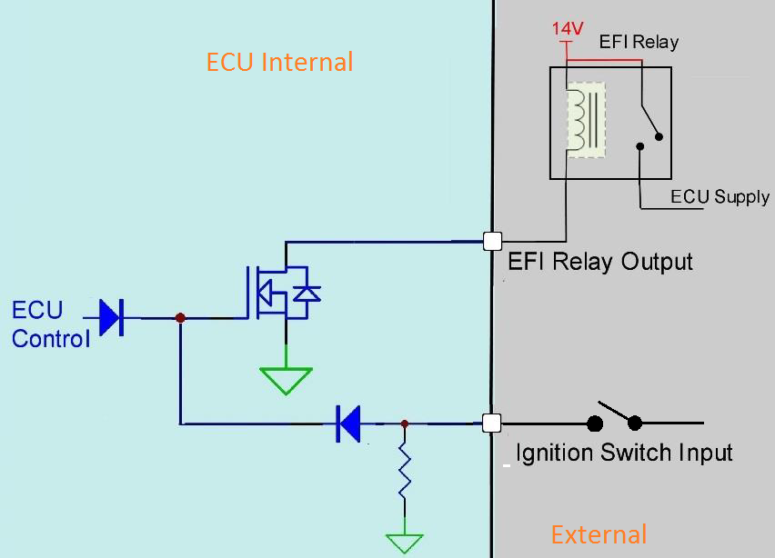
All Emtron ECU systems can control an EFI relay, allowing for management of its own power supply. To achieve this a dedicated Ignition Switch input and dedicated EFI Relay output are used. When 12V is applied to the Ignition Switch input, the ECUs fixed internal circuity switches the EFI Relay output to ground. This can be used to turn ON the Main relay and supply power to the ECU and sub systems. This functionality is controlled at a hardware level, meaning 12V at the Ignition Switch input will ALWAYS make the EFI Relay output turn ON and switch to ground.
Once powered up the ECU takes control of the EFI Relay output, operating independent of the Ignition Switch input. When the Ignition Switch input goes low (turns OFF) this triggers the ECU to enter shutdown mode, but the ECU will only switch the Main relay OFF after all critical self checks have been completed
WarningIt is highly recommended the EFI Relay system be used!By allowing the ECU to control its power supply, when the Ignition Switch input turns OFF the ECU can firstly complete critical tasks before shutting itself down (for example, DBW Self calibration and ECU Logging data storage).
The below image shows the internal operation of the EFI Relay system. The control on the EFI Relay output (Low side driver) is managed by a diode OR gate i.e if the Ignition Switch input is ON OR the ECU Control is ON, the EFI Relay output will be ON and providing a ground.
Dedicated EFI Relay Output
- Provides a relay ground, 200mA Limit.
- Short circuit, thermal overload protection, reverse battery.
KV Series: Pin D9. SL Series: Pin B3.
Dedicated Ignition Switch
- Used to control Main EFI Relay circuit at key-on.
- Input Analog Voltage Range: 0 - 20.0V.
- Input Impedance 100k Ohms to ground.
- Adjustable On/Off software thresholds. Resolution = 0.1V.
KV Series: Pin D15. SL Series: Pin B4.
Power Supply Input
The Emtron ECU system has a main power input to run the ECU (ECU supply pin), but also has the capability to distribute power through various outputs as well. The following power supply pins must be fed 12V in order for the ECU to distribute them to the following outputs (as high side outputs).
SL Series ECU
- Aux 5-8 ECU Supply Pin B1. As well as the main ECU supply, it also provides power to the Aux 5-8 High Side Drivers.
- Aux 9-10 Power Supply Pin A34. Supplies power to Aux 9/10 Half bridge drivers.
KV Series ECU
- Aux 1-8 ECU Supply Pin D1. As well as the main ECU supply, it also provides power to the Aux 1-8 High Side Drivers.
- Aux 9-12 Power Supply Pin D20. Supplies power to Aux 9/12 Half bridge drivers.
- Aux 13-16 Power Supply Input D2. Supplies power to Aux 13/16 Half bridge drivers.
H-Bridge control
Selected outputs can supply either a ground or battery voltage i.e. there is no “off” state, called Half-bridge outputs. Combine two half bridges and this forms an H-bridge configuration.Since the most common use for this type of output is Drive by Wire (DBW), it is necessary to control the supply power to these supply pins via a separate circuit so that the ECU can control this individually (E-throttle Relay Circuit).
This will allow the ECU to disconnect power to that distribution source in the event of an error being detected, but still maintain functionality of the engine, store fault codes, record logs, etc. Most DBW cars will default mechanical throttle position to a “raised” idle, and an extra level of Limp Mode will also function to cut RPM in the event of unintended mechanical acceleration.
SL Series ECU
- H-bridge control for Aux 9-10 (1 pair).
KV8/12 ECU
- H-bridge control for Aux 9-10 / Aux 11-12 (2 pair).
KV16/16M ECU
- H-bridge control for Aux 9-10 / Aux 11-12 / Aux 13-14 / Aux 15-16 (4 pair).
Grounds
Main ECU Grounds
All Emtron grounds are internally linked, however each ECU major section/plug has dedicated grounds. Most ECU functions in general distribute ground connection to operate components (fuel injectors, relays, boost solenoids, etc). Do NOT try to use one single ground since they are all linked. Pay mind to the fact that all of these outputs need to make complete circuits to ground when being activated, and the current limit of each ECU pin is only 12 amps.
Sensor 0V Reference Grounds
These pins are NOT ECU grounds. Although a multi-meter test will show continuity to the ECU ground, these pins are designed as a low current 0V reference for pressure, position and temperature sensors. The following rules MUST always be observed:
WarningDO NOT connect these pins to the ECU main ground location(s)!This is a specialized ground reference for all analog sensors and should be connected directly to the sensor 0V(ground) pin.
WarningDO NOT connect frequency-based sensor grounds to the 0V Reference pin.For example: an Ethanol content sensor. Use the main ECU ground.
Differential Input Grounds
Inputs with +/- (Crank, Sync, Knock) are considered Differential Inputs. These “-” pins are used for as a comparator for the input pin, and are NOT linked to ECU grounds or Sensor 0V Reference grounds (regardless of tested continuity). This is also the reason pulsed signals are safe to be connected to these pins. When wiring these inputs, it is highly recommended to use them without fail, as like the 0V reference for analog volt sensors, the differential input will behave appropriately during all electrical situations such as when voltage drop can be high during cranking, etc.