Shadow 8 Pinout
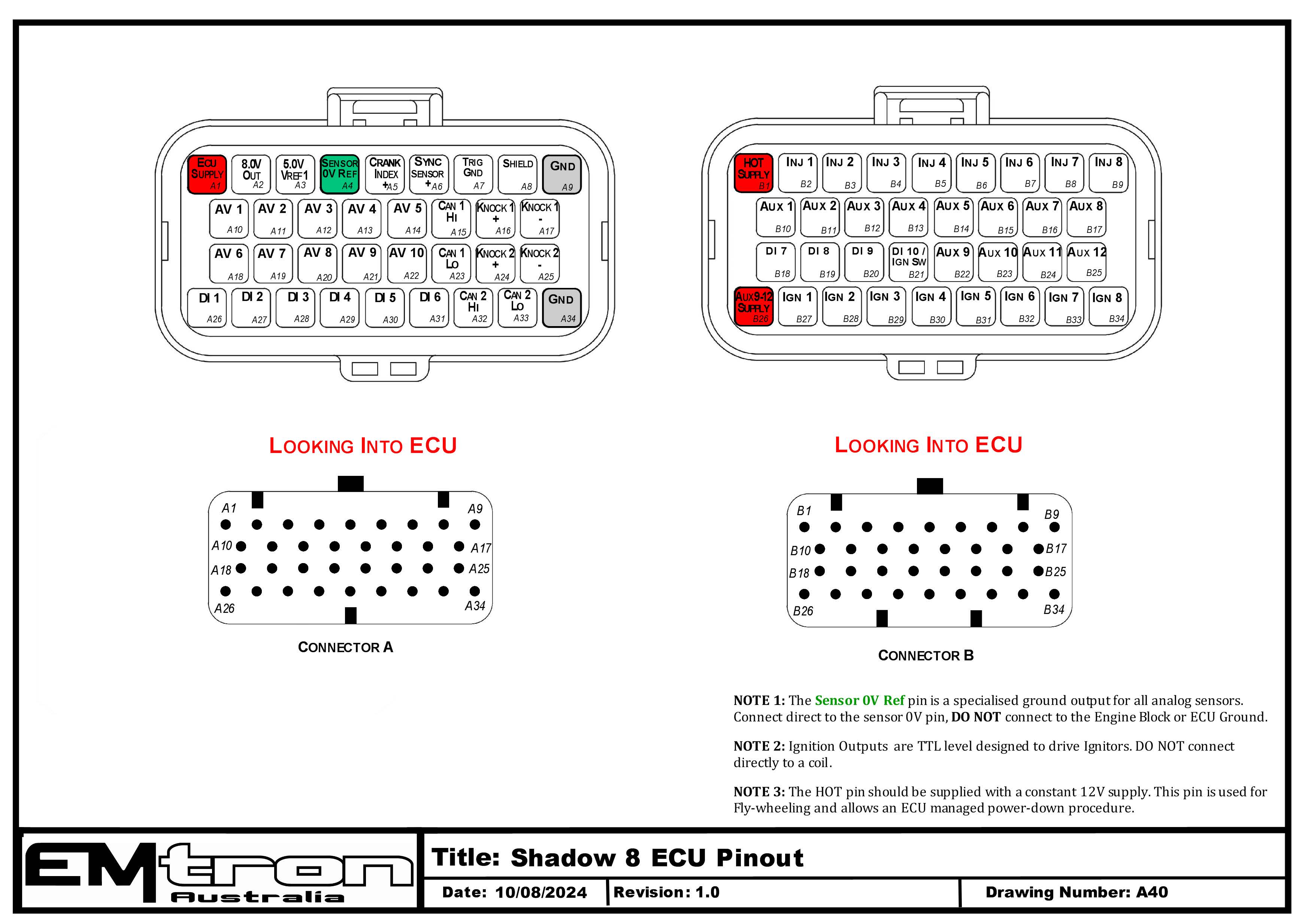
Shadow 8 ECU pinout — Connector A (signal/power) and Connector B (injection/ignition/aux), looking into the ECU connectors (drawing A40).
Connector A: Signal / Power / Communications / Triggers / Knock
(15.0A Max continuous current - wire gauge dependant)
| Pin | Channel Name | Pin | Channel Name |
|---|---|---|---|
| A1 | ECU Supply | A18 | Analog Voltage 6 |
| A2 | Sensor 8.0V Sensor Supply | A19 | Analog Voltage 7 |
| A3 | Sensor 5.0V Sensor Supply | A20 | Analog Voltage 8 |
| A4 | 0V Analog Reference | A21 | Analog Voltage 9 |
| A5 | Crank Position Sensor | A22 | Analog Voltage 10 |
| A6 | Sync Position Sensor | A23 | CAN Bus 1 Low |
| A7 | Trigger Ground | A24 | Knock 2 +ve |
| A8 | Shield | A25 | Knock 2 -ve |
| A9 | Ground 1 | A26 | Digital Input 1 |
| A10 | Analog Voltage 1 | A27 | Digital Input 2 |
| A11 | Analog Voltage 2 | A28 | Digital Input 3 |
| A12 | Analog Voltage 3 | A29 | Digital Input 4 |
| A13 | Analog Voltage 4 | A30 | Digital Input 5 |
| A14 | Analog Voltage 5 | A31 | Digital Input 6 |
| A15 | CAN Bus 1 High | A32 | CAN Bus 2 High |
| A16 | Knock 1 +ve | A33 | CAN Bus 2 Low |
| A17 | Knock 1 -ve | A34 | Ground 2 |
Connector B: Injection / Ignition / Auxiliary Outputs
(15.0A Max continuous current - wire gauge dependant)
| Pin | Channel Name | Pin | Channel Name |
|---|---|---|---|
| B1 | Battery Constant (HOT) Supply | B18 | Digital Input 7 |
| B2 | Injector Cylinder 1 | B19 | Digital Input 8 |
| B3 | Injector Cylinder 2 | B20 | Digital Input 9 |
| B4 | Injector Cylinder 3 | B21 | Digital Input 10 / Ignition Switch |
| B5 | Injector Cylinder 4 | B22 | Aux Output 9 |
| B6 | Injector Cylinder 5 | B23 | Aux Output 10 |
| B7 | Injector Cylinder 6 | B24 | Aux Output 11 |
| B8 | Injector Cylinder 7 | B25 | Aux Output 12 |
| B9 | Injector Cylinder 8 | B26 | Aux 9-12 Power Supply |
| B10 | Aux Output 1 | B27 | Ignition TTL Cylinder 1 |
| B11 | Aux Output 2 | B28 | Ignition TTL Cylinder 2 |
| B12 | Aux Output 3 | B29 | Ignition TTL Cylinder 3 |
| B13 | Aux Output 4 | B30 | Ignition TTL Cylinder 4 |
| B14 | Aux Output 5 | B31 | Ignition TTL Cylinder 5 |
| B15 | Aux Output 6 | B32 | Ignition TTL Cylinder 6 |
| B16 | Aux Output 7 | B33 | Ignition TTL Cylinder 7 |
| B17 | Aux Output 8 | B34 | Ignition TTL Cylinder 8 |
NoteNOTE 1 The Sensor 0V Ref pin (A4) is a specialised ground output for all analog sensors. Connect direct to the sensor 0V pin, DO NOT connect to the Engine Block or ECU Ground.
WarningNOTE 2 Ignition Outputs are TTL level designed to drive Ignitors. DO NOT connect directly to a coil.
ImportantNOTE 3 The HOT pin (B1) should be supplied with a constant 12V supply. This pin is used for fly-wheeling and allows an ECU managed power-down procedure.