Shadow 8 ECU Wiring
Shadow 8 Wiring Harness Specification
1.0 Introduction
This document contains the specification for the Emtron Shadow 8 ECU wiring harness.
- Loom Length = 2.5 meters
- Wire Type = AVSS
NoteNOTE Any unused pins MUST have blanking bungs fitted to the connector to keep the plug rated at its IP standard.
2.0 Connector A
| Property | Value |
|---|---|
| Name | Superseal |
| Manufacturer | TE |
| Description | 34 Way / Key 1 |
| Part Number | 4-1437290-0 |
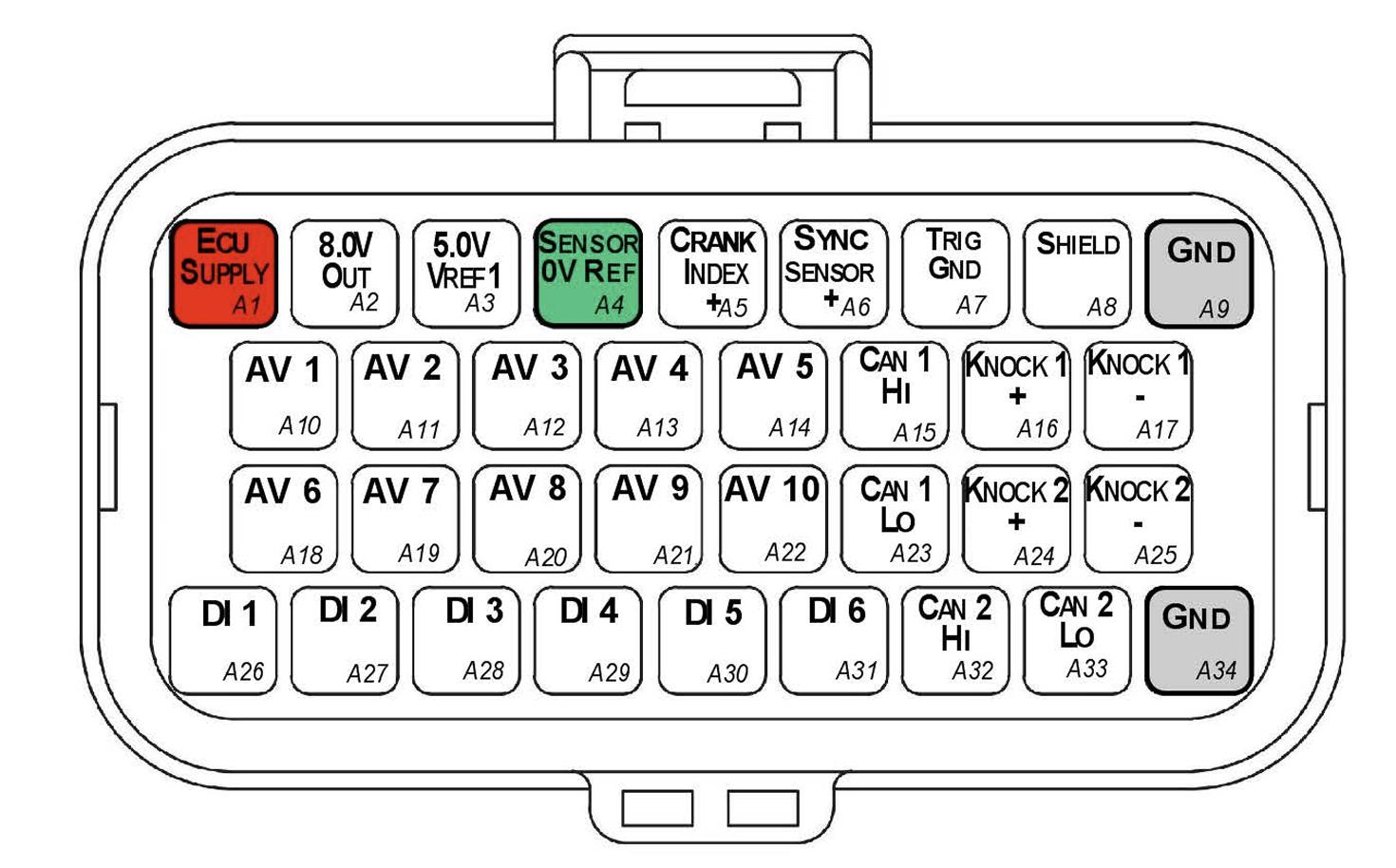
Connector A — TE Superseal 34 Way / Key 1.
2.1 Connector A Wire Colours
| Pin Name | Pin | Description | Colour | Wire Size (sq mm) |
|---|---|---|---|---|
| ECU SUPPLY | A1 | ECU Supply | Red | 0.85 |
| 8.0V OUT | A2 | 8V Cas Supply | Blue | 0.50 |
| 5.0V VREF1 | A3 | Main 5V engine sensor supply (Branched Cable) | Orange | 0.50 |
| SENSOR 0V REF | A4 | Sensor Ground (Branched Cable) | Black | 0.50 |
| CRANK INDEX + | A5 | Crank Index position sensor Positive | 2 core Shielded Cable (shared with A7) | — |
| SYNC SENSOR + | A6 | Sync Sensor Positive | 2 core Shielded Cable (shared with A7) | — |
| TRIG GND | A7 | Trigger Ground (Branched Cable, Black 70mm) | Black | 0.50 |
| SHIELD | A8 | Knock/Trigger Shield (White 70mm) | White | 0.50 |
| GND | A9 | Power Ground | Black | 0.85 |
| AV1 | A10 | Analog Voltage CH 1 | White | 0.50 |
| AV2 | A11 | Analog Voltage CH 2 | White | 0.50 |
| AV3 | A12 | Analog Voltage CH 3 | White | 0.50 |
| AV4 | A13 | Analog Voltage CH 4 | White | 0.50 |
| AV5 | A14 | Analog Voltage CH 5 | White | 0.50 |
| CAN 1 HI | A15 | Main Engine CAN | White | 0.50 |
| KNK 1 + | A16 | Knock Sensor 1 + | 2 core Shielded Cable (shared with A17) | — |
| KNK 1 - | A17 | Knock Sensor 1 - | 2 core Shielded Cable (shared with A16) | — |
| AV6 | A18 | Analog Voltage CH 6 | White | 0.50 |
| AV7 | A19 | Analog Voltage CH 7 | White | 0.50 |
| AV8 | A20 | Analog Voltage CH 8 | White | 0.50 |
| AV9 | A21 | Analog Voltage CH 9 | White | 0.50 |
| AV10 | A22 | Analog Voltage CH 10 | White | 0.50 |
| CAN 1 LO | A23 | Main Engine CAN | Green | 0.50 |
| KNK 2 + | A24 | Knock Sensor 2 + | 2 core Shielded Cable (shared with A25) | — |
| KNK 2 - | A25 | Knock Sensor 2 - | 2 core Shielded Cable (shared with A24) | — |
| DI 1 | A26 | Digital Input CH 1 | White | 0.50 |
| DI 2 | A27 | Digital Input CH 2 | White | 0.50 |
| DI 3 | A28 | Digital Input CH 3 | White | 0.50 |
| DI 4 | A29 | Digital Input CH 4 | White | 0.50 |
| DI 5 | A30 | Digital Input CH 5 | White | 0.50 |
| DI 6 | A31 | Digital Input CH 6 | White | 0.50 |
| CAN 2 HI | A32 | Auxiliary CAN | White | 0.50 |
| CAN 2 LO | A33 | Auxiliary CAN | Green | 0.50 |
| GND | A34 | Power Ground | Black | 0.85 |
3.0 Connector B
| Property | Value |
|---|---|
| Name | Superseal |
| Manufacturer | TE |
| Description | 34 Way / Key 2 |
| Part Number | 4-1437290-1 |
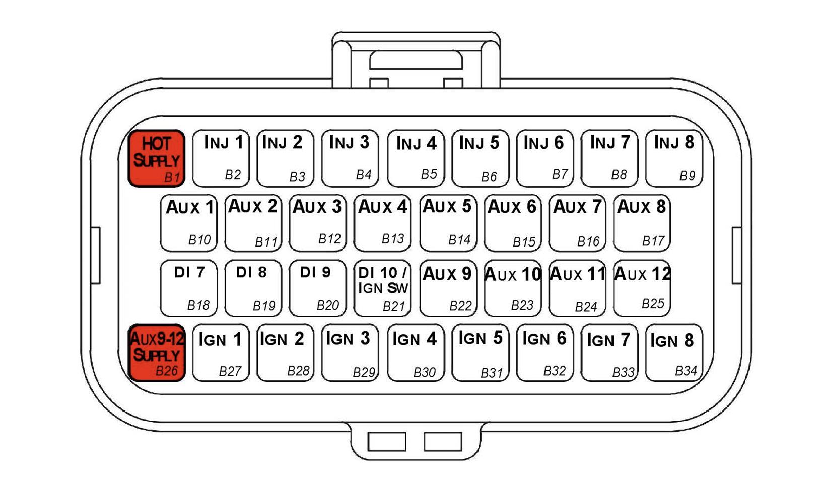
Connector B — TE Superseal 34 Way / Key 2.
3.1 Connector B Wire Colours
| Pin Name | Pin | Description | Colour | Wire Size (sq mm) |
|---|---|---|---|---|
| HOT SUPPLY | B1 | ECU +12V Constant | Red | 0.85 |
| INJ 1 | B2 | Injector Channel 1 | Blue | 0.50 |
| INJ 2 | B3 | Injector Channel 2 | Blue | 0.50 |
| INJ 3 | B4 | Injector Channel 3 | Blue | 0.50 |
| INJ 4 | B5 | Injector Channel 4 | Blue | 0.50 |
| INJ 5 | B6 | Injector Channel 5 | Blue | 0.50 |
| INJ 6 | B7 | Injector Channel 6 | Blue | 0.50 |
| INJ 7 | B8 | Injector Channel 7 | Blue | 0.50 |
| INJ 8 | B9 | Injector Channel 8 | Blue | 0.50 |
| AUX 1 | B10 | Auxiliary Channel 1 | Grey | 0.50 |
| AUX 2 | B11 | Auxiliary Channel 2 | Grey | 0.50 |
| AUX 3 | B12 | Auxiliary Channel 3 | Grey | 0.50 |
| AUX 4 | B13 | Auxiliary Channel 4 | Grey | 0.50 |
| AUX 5 | B14 | Auxiliary Channel 5 | Grey | 0.50 |
| AUX 6 | B15 | Auxiliary Channel 6 | Grey | 0.50 |
| AUX 7 | B16 | Auxiliary Channel 7 | Grey | 0.50 |
| AUX 8 | B17 | Auxiliary Channel 8 | Grey | 0.50 |
| DI 7 | B18 | Digital Input CH 7 | White | 0.50 |
| DI 8 | B19 | Digital Input CH 8 | White | 0.50 |
| DI 9 | B20 | Digital Input CH 9 | White | 0.50 |
| DI 10 / IGN SW | B21 | Digital Input CH 10 | White | 0.50 |
| AUX 9 | B22 | Auxiliary Channel 9 | Grey | 0.50 |
| AUX 10 | B23 | Auxiliary Channel 10 | Grey | 0.50 |
| AUX 11 | B24 | Auxiliary Channel 11 | Grey | 0.50 |
| AUX 12 | B25 | Auxiliary Channel 12 | Grey | 0.50 |
| AUX 9-12 SUPPLY | B26 | Aux 9-12 Supply | Red | 0.85 |
| IGN 1 | B27 | Ignition Channel 1 | Yellow | 0.50 |
| IGN 2 | B28 | Ignition Channel 2 | Yellow | 0.50 |
| IGN 3 | B29 | Ignition Channel 3 | Yellow | 0.50 |
| IGN 4 | B30 | Ignition Channel 4 | Yellow | 0.50 |
| IGN 5 | B31 | Ignition Channel 5 | Yellow | 0.50 |
| IGN 6 | B32 | Ignition Channel 6 | Yellow | 0.50 |
| IGN 7 | B33 | Ignition Channel 7 | Yellow | 0.50 |
| IGN 8 | B34 | Ignition Channel 8 | Yellow | 0.50 |
3.2 Pin A4 Sensor Ground Branched Connections
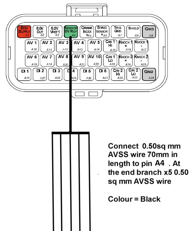
Pin A4 (Sensor 0V Ref) is a branched connection feeding the analog sensor 0V references.
3.3 Pin A3 5V Supply Branched Connections
Pin A3 (5.0V VRef1) is a branched connection feeding the engine sensor 5V supply.
3.4 Crank and Sync Shielded Cable Connections
- Use x1 2-core shielded cable for Pins A5 and A7 (Crank Index)
- Use x1 2-core shielded cable for Pins A6 and A7 (Sync Sensor)
NoteNOTE The individual core colours are not specified but there MUST be at least one different core colour between the Crank Index cable and Sync Sensor cable — i.e. the exact same cables cannot be used for both connections.
3.5 Knock Shielded Cable Connections
- Use x1 2-core shielded cable for Pins A16 and A17
- Use x1 2-core shielded cable for Pins A24 and A25
NoteNOTE The individual core colours are not specified but there MUST be at least one different core colour between the KNK 1 cable and KNK 2 cable — i.e. the exact same cables cannot be used for both connections. Ideally these core colours should also be different to those used in section 3.4.
Appendix A – Shadow 8 ECU Pinout Drawing
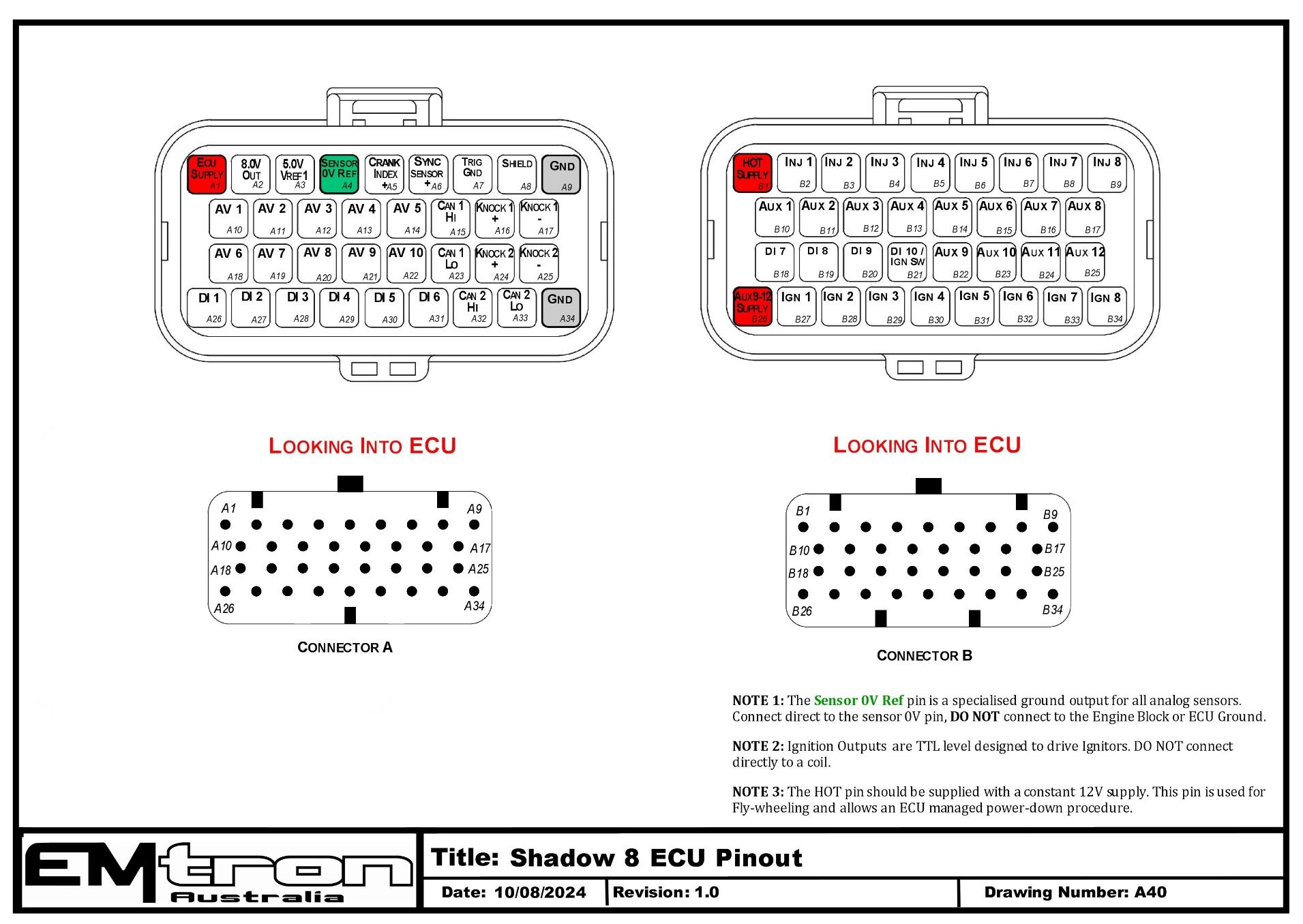
Shadow 8 ECU pinout — Connector A (signal/power) and Connector B (injection/ignition/aux), looking into the ECU (drawing A40).
Appendix B – Shadow Series ECU Wiring
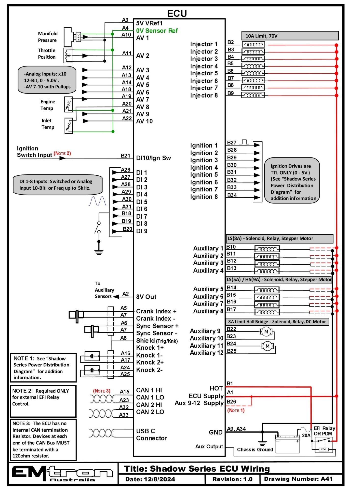
Shadow Series ECU wiring overview (drawing A41).