Shadow 8 Power Distribution Wiring
Shadow Power Supply System
The Shadow 8 power supply system has been designed to allow flexibility on how the ECU manages power-up and power-down sequencing.
The real advantage is on the power-down sequence, allowing the ECU to power-down once all pending tasks have been completed. This effectively acts as an internal Hold Power System.
ECU Supply (Pin A1)
Pin A1 is the main power supply into the ECU .
Battery Constant Supply (Pin B1)
ImportantPin B1 is a permanent power supply and should ALWAYS be connected to a constant 12V supply.ALL Auxiliary flywheel control is directed to the pin; therefore, this pin MUST always have power connected.
Note: The ECU draws zero current once completely shut down.
Aux 9-12 (Half Bridge) Driver Power Supply (Pin B26)
Pin B26 is a dedicated power supply for Auxiliary Channels 9-12. Power must be supplied to this pin for these channels to operate correctly.
In non-DBW (Drive by Wire) applications the ECU Supply can be shared, assuming the wire gauge has a sufficient rating for the current demand.
ImportantIn DBW applications power to this pin MUST come from an ECU controlled DBW Relay.ECU Power Supply Wiring
The ECU power supply can be configured in one of two ways; both options assume constant power is fed to pin B1.
OPTION A – Power Supply Pin Controlled
This is the main option for ECU Power Supply control.
Power-On
Power to the ECU Supply pin A1 can be switched ON using a PDM or from an Ignition switch controlled relay. When the ECU detects power on this pin, it will power up.
Power-Off
When the ECU Supply falls below 6.0V the ECU enters a Shutdown Sequence and uses the Constant Supply to remain ON during this process.
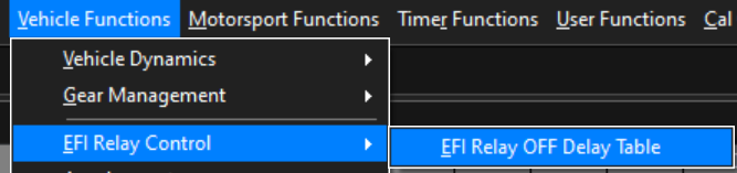
The ECU uses the time value from the “EFI Relay OFF table” to determine Power-down. However, the following tasks will prevent an ECU power-down:
- ECU CAL file Store in progress
- ECU Datalogging Store in progress
- Emtune connected. (Emtune must be disconnected for the ECU to power-down)
Once the ECU has completed all shut down tasks, and the EFI Relay OFF Delay time has elapsed, the ECU will power-down.
ECU Settings
The following settings must be configured for this mode to operate.
Ignition Switch Source Input selected to OFF

EFI Relay OFF Time
OPTION B – Ignition Switch Pin Controlled
This mode should only be used when the ECU needs to control an external EFI Relay, normally in OEM applications.
Power-On
This option uses the Ignition Switch Input, shared with DI10(Pin B21) to power-up the ECU.
When Ignition Switch Input Pin B21 is > 6.0V, the internal circuity will turn the ECU ON using the Battery Constant supply.
Once powered on, the ECU can switch/control an external OEM EFI relay using one of the ECU outputs.
For example, Aux 8 could be configured as a High Side Output, suppling power to a relay coil and turning it ON, which in turn supplies power to the ECU Pin A1.
Power-Off
When the Ignition Switch falls below 6.0V the ECU enters the Shutdown Sequence. The same shutdown conditions apply as outlined in Option A.
ECU Settings
The following settings must be configured for this mode to operate.
Ignition Switch Source Input selected to Dedicated – Ign -Sw. In this case this input is shared with DI10.

EFI Relay OFF Time

IMPORTANT NOTE
Regardless of the ECU’s settings, a high input on DI10 will cause the ECU to power up. Care should be taken to not unintentionally supply power to this pin.