Subsections of SL Series
SL4 Pinout
Pin Descriptions
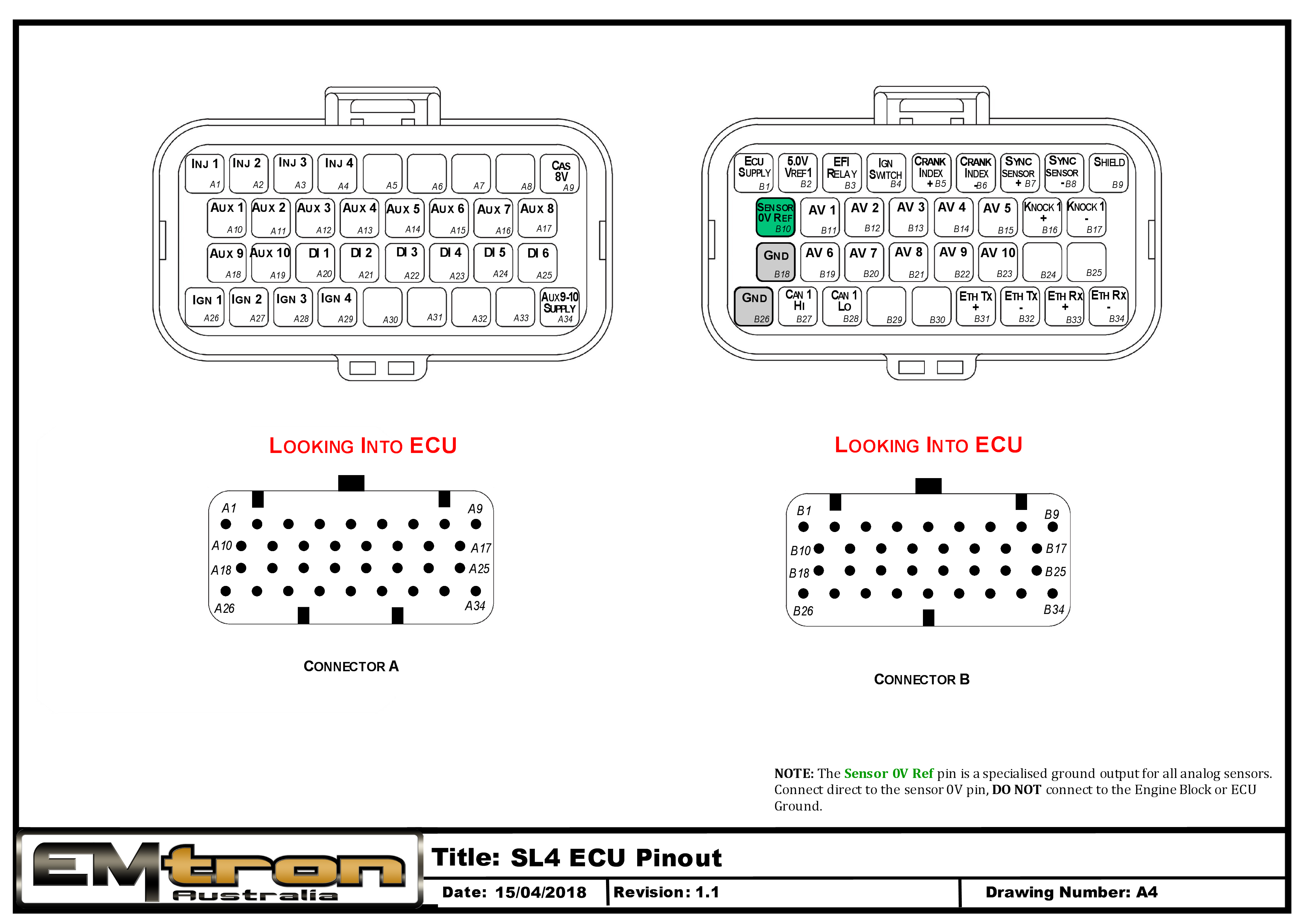
| Connector A: Injection/Ignition/Auxiliary Outputs (15.0A Max continuous current - wire gauge dependant) |
|---|
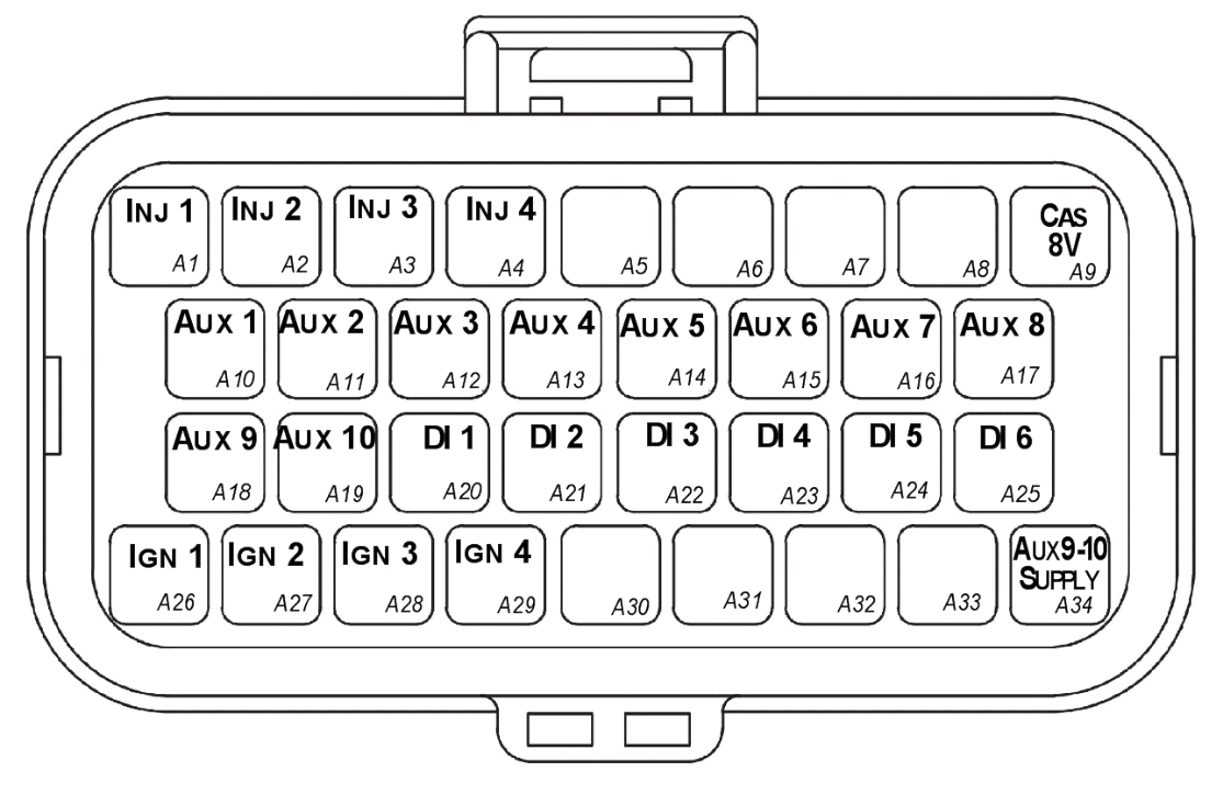
Looking into ECU connector
| Pin | Channel Name | Pin | Channel Name |
|---|---|---|---|
| A1 | Injection Channel 1 | A18 | Auxiliary Output 9 |
| A2 | Injection Channel 2 | A19 | Auxiliary Output 10 |
| A3 | Injection Channel 3 | A20 | Digital Input 1 |
| A4 | Injection Channel 4 | A21 | Digital Input 2 |
| A5 | NC | A22 | Digital Input 3 |
| A6 | NC | A23 | Digital Input 4 |
| A7 | NC | A24 | Digital Input 5 |
| A8 | NC | A25 | Digital Input 6 |
| A9 | Sensor Supply 8V | A26 | Ignition Channel 1 |
| A10 | Auxiliary Output 1 | A27 | Ignition Channel 2 |
| A11 | Auxiliary Output 2 | A28 | Ignition Channel 3 |
| A12 | Auxiliary Output 3 | A29 | Ignition Channel 4 |
| A13 | Auxiliary Output 4 | A30 | NC |
| A14 | Auxiliary Output 5 | A31 | NC |
| A15 | Auxiliary Output 6 | A32 | NC |
| A16 | Auxiliary Output 7 | A33 | NC |
| A17 | Auxiliary Output 8 | A34 | Auxiliary Output 9-10, 14V Supply |
| Connector B: Signal/Power/Communications/Triggers/Knock (15.0A Max continuous current - wire gauge dependant) |
|---|
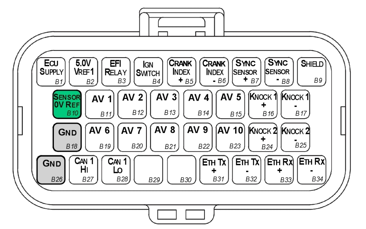
Looking into ECU connector
| Pin | Channel Name | Pin | Channel Name |
|---|---|---|---|
| B1 | ECU 14V Supply | B18 | ECU Ground |
| B2 | Sensor Supply Vref1: 5.0V | B19 | Analog Input Channel 6 |
| B3 | EFI Relay Output (Low Side 200mA) | B20 | Analog Input Channel 7 |
| B4 | Ignition Switch Input | B21 | Analog Input Channel 8 |
| B5 | Crank Index Sensor + | B22 | Analog Input Channel 9 |
| B6 | Crank Index Sensor - | B23 | Analog Input Channel 10 |
| B7 | Sync Sensor + | B24 | Knock 2 + |
| B8 | Sync Sensor - | B25 | Knock 2 - |
| B9 | Shield (Crank/Sync/ Knock) | B26 | ECU Ground |
| B10 | Analog Sensor 0V Reference | B27 | CAN 1H |
| B11 | Analog Input Channel 1 | B28 | CAN 1L |
| B12 | Analog Input Channel 2 | B29 | NC |
| B13 | Analog Input Channel 3 | B30 | NC |
| B14 | Analog Input Channel 4 | B31 | Ethernet Tx + |
| B15 | Analog Input Channel 5 | B32 | Ethernet Tx - |
| B16 | Knock 1 + | B33 | Ethernet Rx + |
| B17 | Knock 1 - | B34 | Ethernet Rx - |
Important Notes
Analog Sensor 0V Reference (Pin B10)
This pin should be connected directly to the 0V (Ground) pin on any low current analog sensor, for example Pressure or Temperature.
- DO NOT connect the ECU pin B10 directly to the Engine Block or ECU Ground. These are dedicated and specialised ground outputs for all analog channels and should be connected directly to the sensor.
- DO NOT connect frequency-based sensors to these pins; for example, an Ethanol content sensor. The sensor 0V pin should be connected to the ECU ground.
Half Bridge Driver Power Supply Input (Pin A34)
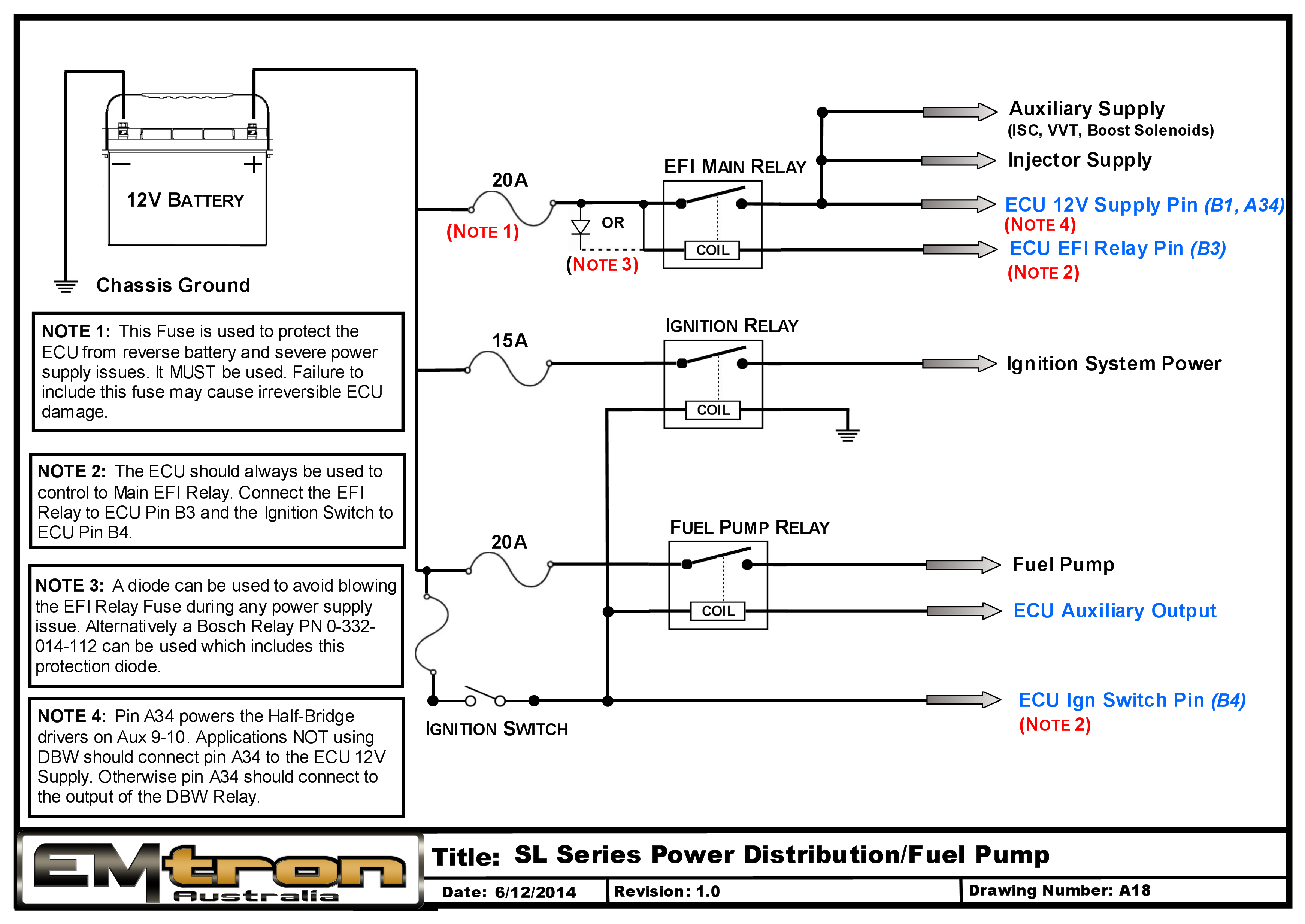
Pin A34 is a dedicated power supply for Auxiliary Channels 9-10. Power must be supplied to this pin for these channels to operate correctly. In non-DBW (Drive by Wire) applications the ECU Supply power can be shared, assuming the wire gauge has a sufficient rating for the current demand. In DBW applications power to this pin MUST come from an ECU controlled DBW Relay.
SL6 Pinout
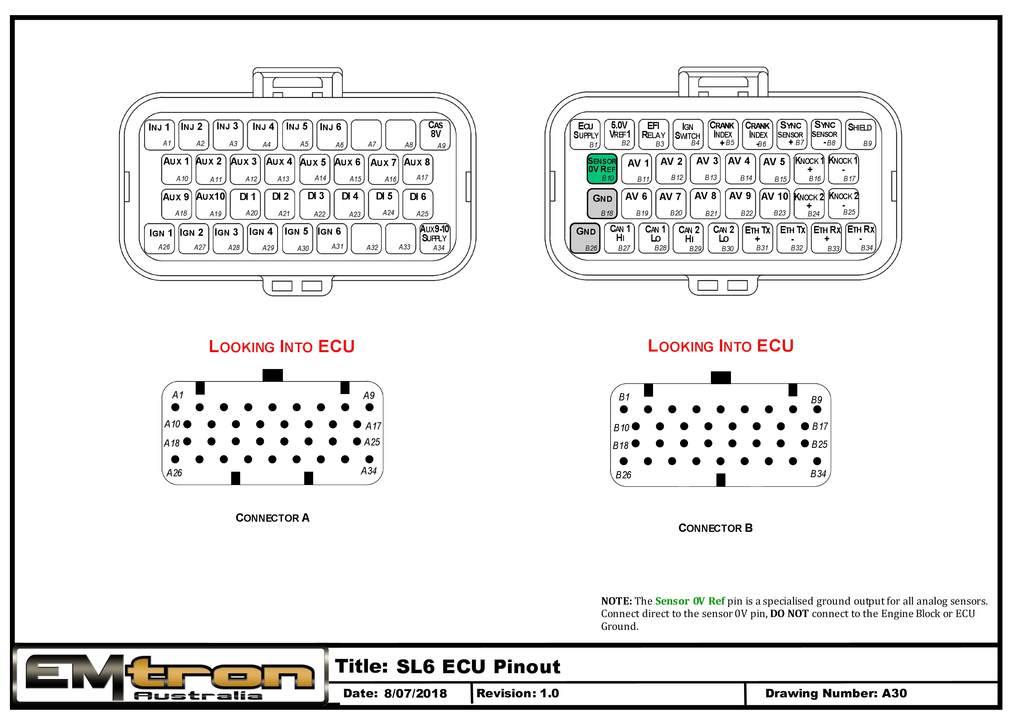
Pin Descriptions
| Connector A: Injection/Ignition/Auxiliary Outputs (15.0A Max continuous current - wire gauge dependant) |
|---|
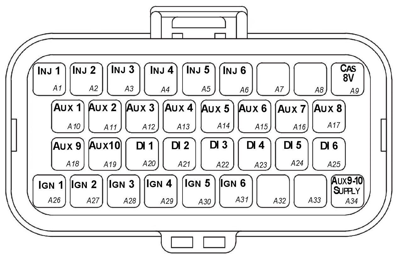
Looking into ECU connector
| Pin | Channel Name | Pin | Channel Name |
|---|---|---|---|
| A1 | Injection Channel 1 | A18 | Auxiliary Output 9 |
| A2 | Injection Channel 2 | A19 | Auxiliary Output 10 |
| A3 | Injection Channel 3 | A20 | Digital Input 1 |
| A4 | Injection Channel 4 | A21 | Digital Input 2 |
| A5 | Injection Channel 5 | A22 | Digital Input 3 |
| A6 | Injection Channel 6 | A23 | Digital Input 4 |
| A7 | NC | A24 | Digital Input 5 |
| A8 | NC | A25 | Digital Input 6 |
| A9 | Sensor Supply 8V | A26 | Ignition Channel 1 |
| A10 | Auxiliary Output 1 | A27 | Ignition Channel 2 |
| A11 | Auxiliary Output 2 | A28 | Ignition Channel 3 |
| A12 | Auxiliary Output 3 | A29 | Ignition Channel 4 |
| A13 | Auxiliary Output 4 | A30 | Ignition Channel 5 |
| A14 | Auxiliary Output 5 | A31 | Ignition Channel 6 |
| A15 | Auxiliary Output 6 | A32 | NC |
| A16 | Auxiliary Output 7 | A33 | NC |
| A17 | Auxiliary Output 8 | A34 | Auxiliary Output 9-10, 14V Supply |
| Connector B: Signal/Power/Communications/Triggers/Knock (15.0A Max continuous current - wire gauge dependant) |
|---|
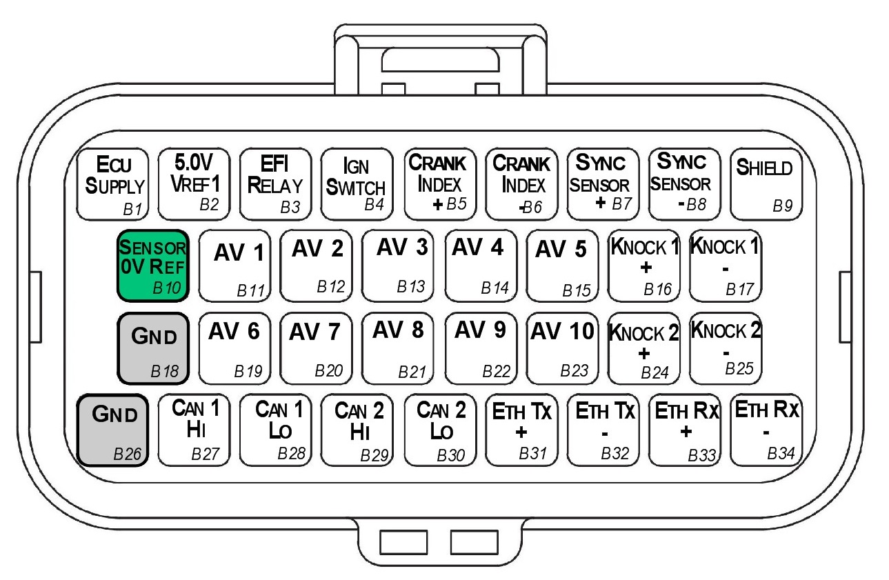
Looking into ECU connector
| Pin | Channel Name | Pin | Channel Name |
|---|---|---|---|
| B1 | ECU 14V Supply | B18 | ECU Ground |
| B2 | Sensor Supply Vref1: 5.0V | B19 | Analog Input Channel 6 |
| B3 | EFI Relay Output (Low Side 200mA) | B20 | Analog Input Channel 7 |
| B4 | Ignition Switch Input | B21 | Analog Input Channel 8 |
| B5 | Crank Index Sensor + | B22 | Analog Input Channel 9 |
| B6 | Crank Index Sensor - | B23 | Analog Input Channel 10 |
| B7 | Sync Sensor + | B24 | Knock 2 + |
| B8 | Sync Sensor - | B25 | Knock 2 - |
| B9 | Shield (Crank/Sync/ Knock) | B26 | ECU Ground |
| B10 | Analog Sensor 0V Reference | B27 | CAN 1H |
| B11 | Analog Input Channel 1 | B28 | CAN 1L |
| B12 | Analog Input Channel 2 | B29 | NC |
| B13 | Analog Input Channel 3 | B30 | NC |
| B14 | Analog Input Channel 4 | B31 | Ethernet Tx + |
| B15 | Analog Input Channel 5 | B32 | Ethernet Tx - |
| B16 | Knock 1 + | B33 | Ethernet Rx + |
| B17 | Knock 1 - | B34 | Ethernet Rx - |
Important Notes
Analog Sensor 0V Reference (Pin B10)
This pin should be connected directly to the 0V (Ground) pin on any low current analog sensor, for example Pressure or Temperature.
- DO NOT connect the ECU pin B10 directly to the Engine Block or ECU Ground. These are dedicated and specialised ground outputs for all analog channels and should be connected directly to the sensor.
- DO NOT connect frequency-based sensors to these pins; for example, an Ethanol content sensor. The sensor 0V pin should be connected to the ECU ground.
Half Bridge Driver Power Supply Input (Pin A34)
Pin A34 is a dedicated power supply for Auxiliary Channels 9-10. Power must be supplied to this pin for these channels to operate correctly. In non-DBW (Drive by Wire) applications the ECU Supply power can be shared, assuming the wire gauge has a sufficient rating for the current demand. In DBW applications power to this pin MUST come from an ECU controlled DBW Relay.
SL8 Pinout
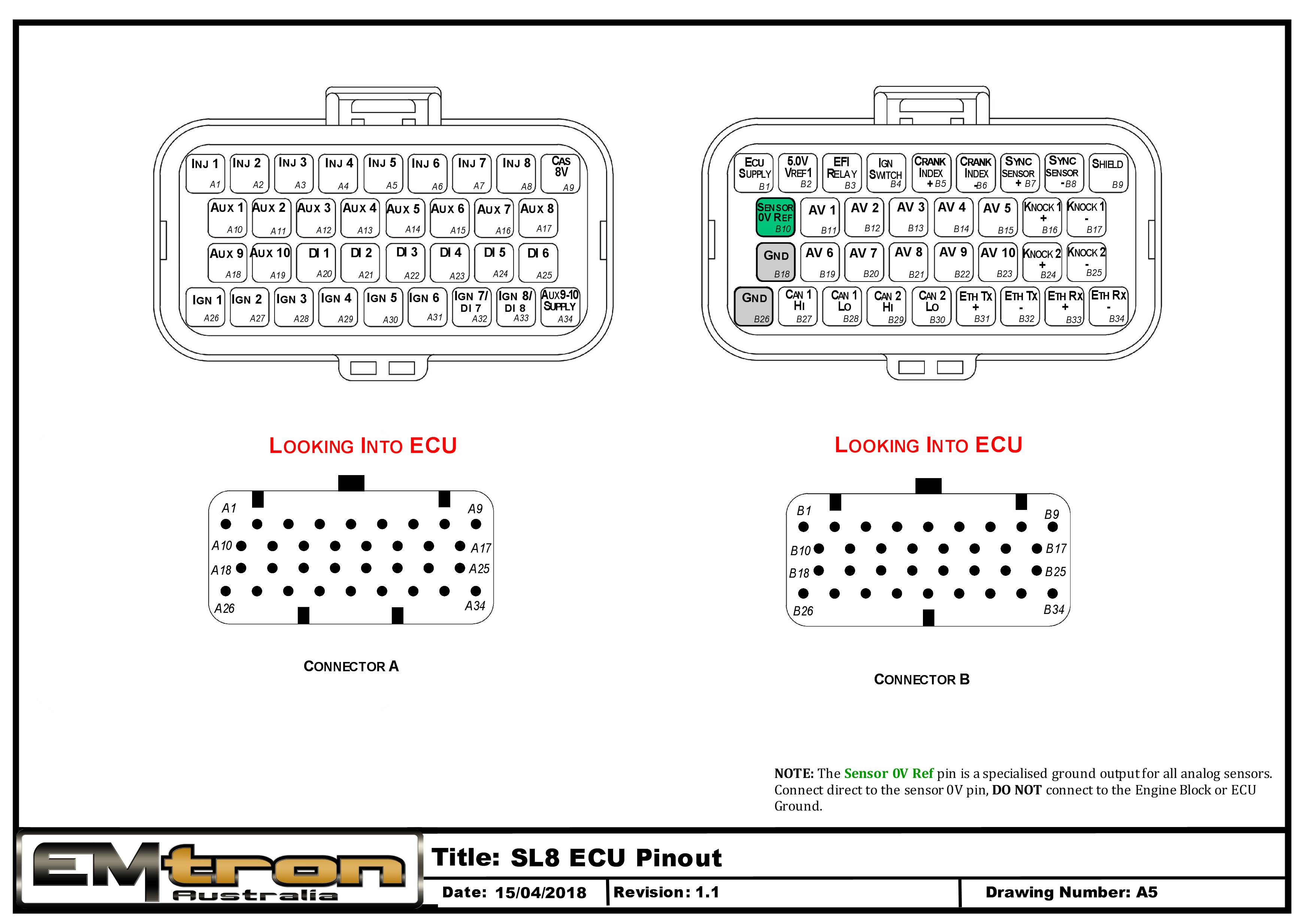
Pin Descriptions
| Connector A: Injection/Ignition/Auxiliary Outputs (15.0A Max continuous current - wire gauge dependant) |
|---|
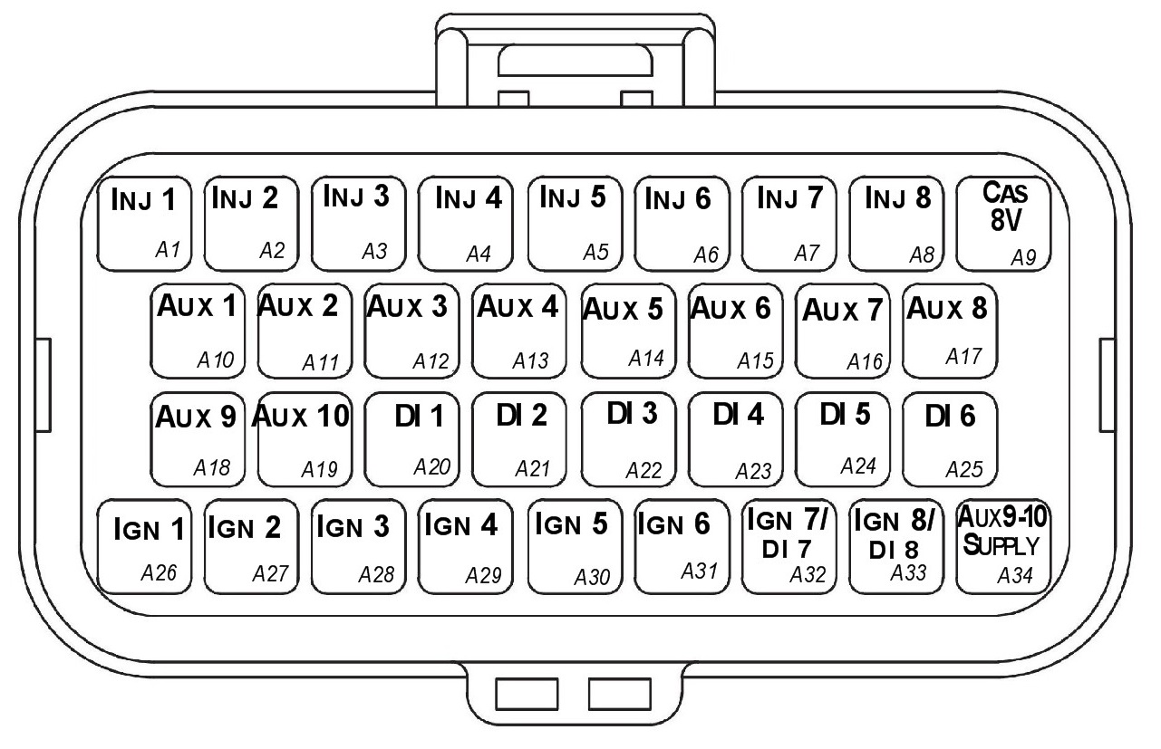
Looking into ECU connector
| Pin | Channel Name | Pin | Channel Name |
|---|---|---|---|
| A1 | Injection Channel 1 | A18 | Auxiliary Output 9 |
| A2 | Injection Channel 2 | A19 | Auxiliary Output 10 |
| A3 | Injection Channel 3 | A20 | Digital Input 1 |
| A4 | Injection Channel 4 | A21 | Digital Input 2 |
| A5 | Injection Channel 5 | A22 | Digital Input 3 |
| A6 | Injection Channel 6 | A23 | Digital Input 4 |
| A7 | Injection Channel 7 | A24 | Digital Input 5 |
| A8 | Injection Channel 8 | A25 | Digital Input 6 |
| A9 | Sensor Supply 8V | A26 | Ignition Channel 1 |
| A10 | Auxiliary Output 1 | A27 | Ignition Channel 2 |
| A11 | Auxiliary Output 2 | A28 | Ignition Channel 3 |
| A12 | Auxiliary Output 3 | A29 | Ignition Channel 4 |
| A13 | Auxiliary Output 4 | A30 | Ignition Channel 5 |
| A14 | Auxiliary Output 5 | A31 | Ignition Channel 6 |
| A15 | Auxiliary Output 6 | A32 | Ignition Channel 7 |
| A16 | Auxiliary Output 7 | A33 | Ignition Channel 8 |
| A17 | Auxiliary Output 8 | A34 | Auxiliary Output 9-10, 14V Supply |
| Connector B: Signal/Power/Communications/Triggers/Knock (15.0A Max continuous current - wire gauge dependant) |
|---|
Looking into ECU connector
| Pin | Channel Name | Pin | Channel Name |
|---|---|---|---|
| B1 | ECU 14V Supply | B18 | ECU Ground |
| B2 | Sensor Supply Vref1: 5.0V | B19 | Analog Input Channel 6 |
| B3 | EFI Relay Output (Low Side 200mA) | B20 | Analog Input Channel 7 |
| B4 | Ignition Switch Input | B21 | Analog Input Channel 8 |
| B5 | Crank Index Sensor + | B22 | Analog Input Channel 9 |
| B6 | Crank Index Sensor - | B23 | Analog Input Channel 10 |
| B7 | Sync Sensor + | B24 | Knock 2 + |
| B8 | Sync Sensor - | B25 | Knock 2 - |
| B9 | Shield (Crank/Sync/ Knock) | B26 | ECU Ground |
| B10 | Analog Sensor 0V Reference | B27 | CAN 1H |
| B11 | Analog Input Channel 1 | B28 | CAN 1L |
| B12 | Analog Input Channel 2 | B29 | NC |
| B13 | Analog Input Channel 3 | B30 | NC |
| B14 | Analog Input Channel 4 | B31 | Ethernet Tx + |
| B15 | Analog Input Channel 5 | B32 | Ethernet Tx - |
| B16 | Knock 1 + | B33 | Ethernet Rx + |
| B17 | Knock 1 - | B34 | Ethernet Rx - |
Important Notes
Analog Sensor 0V Reference (Pin B10)
This pin should be connected directly to the 0V (Ground) pin on any low current analog sensor, for example Pressure or Temperature.
- DO NOT connect the ECU pin B10 directly to the Engine Block or ECU Ground. These are dedicated and specialised ground outputs for all analog channels and should be connected directly to the sensor.
- DO NOT connect frequency-based sensors to these pins; for example, an Ethanol content sensor. The sensor 0V pin should be connected to the ECU ground.
Half Bridge Driver Power Supply Input (Pin A34)
Pin A34 is a dedicated power supply for Auxiliary Channels 9-10. Power must be supplied to this pin for these channels to operate correctly. In non-DBW (Drive by Wire) applications the ECU Supply power can be shared, assuming the wire gauge has a sufficient rating for the current demand. In DBW applications power to this pin MUST come from an ECU controlled DBW Relay.
SL Series Wiring Harness Specification
1.0 Introduction
This document contains the specification for the Emtron SL Series wiring harness.
- Loom Length = 2.5 meters
- Wire Type = AVSS
NoteNOTE Any unused pins MUST have blanking bungs fitted to the connector to keep the plug rated at its IP standard.
2.0 Connector A
| Property | Value |
|---|---|
| Name | Superseal |
| Manufacturer | TE |
| Description | 34 Way / Key 2 |
| Part Number | 4-1437290-1 |
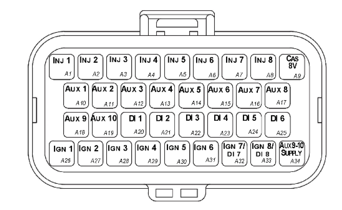
Connector A — TE Superseal 34 Way / Key 2.
2.1 Connector A Wire Colours
| Pin Name | Pin | Description | Colour | Wire Size (sq mm) |
|---|---|---|---|---|
| INJ 1 | A1 | Injector Channel 1 | Blue | 0.50 |
| INJ 2 | A2 | Injector Channel 2 | Blue | 0.50 |
| INJ 3 | A3 | Injector Channel 3 | Blue | 0.50 |
| INJ 4 | A4 | Injector Channel 4 | Blue | 0.50 |
| INJ 5 | A5 | Injector Channel 5 | Blue | 0.50 |
| INJ 6 | A6 | Injector Channel 6 | Blue | 0.50 |
| INJ 7 | A7 | Injector Channel 7 | Blue | 0.50 |
| INJ 8 | A8 | Injector Channel 8 | Blue | 0.50 |
| CAS 8V | A9 | 8V Cas Supply | White/Orange | 0.50 |
| AUX 1 | A10 | Auxiliary Channel 1 | Grey | 0.50 |
| AUX 2 | A11 | Auxiliary Channel 2 | Grey | 0.50 |
| AUX 3 | A12 | Auxiliary Channel 3 | Grey | 0.50 |
| AUX 4 | A13 | Auxiliary Channel 4 | Grey | 0.50 |
| AUX 5 | A14 | Auxiliary Channel 5 | Grey | 0.50 |
| AUX 6 | A15 | Auxiliary Channel 6 | Grey | 0.50 |
| AUX 7 | A16 | Auxiliary Channel 7 | Grey | 0.50 |
| AUX 8 | A17 | Auxiliary Channel 8 | Grey | 0.50 |
| AUX 9 | A18 | Auxiliary Channel 9 | Grey | 0.50 |
| AUX 10 | A19 | Auxiliary Channel 10 | Grey | 0.50 |
| DI 1 | A20 | Digital Input CH 1 | White | 0.50 |
| DI 2 | A21 | Digital Input CH 2 | White | 0.50 |
| DI 3 | A22 | Digital Input CH 3 | White | 0.50 |
| DI 4 | A23 | Digital Input CH 4 | White | 0.50 |
| DI 5 | A24 | Digital Input CH 5 | White | 0.50 |
| DI 6 | A25 | Digital Input CH 6 | White | 0.50 |
| IGN 1 | A26 | Ignition Channel 1 | Yellow | 0.50 |
| IGN 2 | A27 | Ignition Channel 2 | Yellow | 0.50 |
| IGN 3 | A28 | Ignition Channel 3 | Yellow | 0.50 |
| IGN 4 | A29 | Ignition Channel 4 | Yellow | 0.50 |
| IGN 5 | A30 | Ignition Channel 5 | Yellow | 0.50 |
| IGN 6 | A31 | Ignition Channel 6 | Yellow | 0.50 |
| IGN 7 / DI 7 | A32 | Ignition Channel 7 | Yellow | 0.50 |
| IGN 8 / DI 8 | A33 | Ignition Channel 8 | Yellow | 0.50 |
| AUX 9-10 SUPPLY | A34 | Power supply for Aux 9-10 high side | Red | 0.85 |
3.0 Connector B
| Property | Value |
|---|---|
| Name | Superseal |
| Manufacturer | TE |
| Description | 34 Way / Key 1 |
| Part Number | 4-1437290-0 |
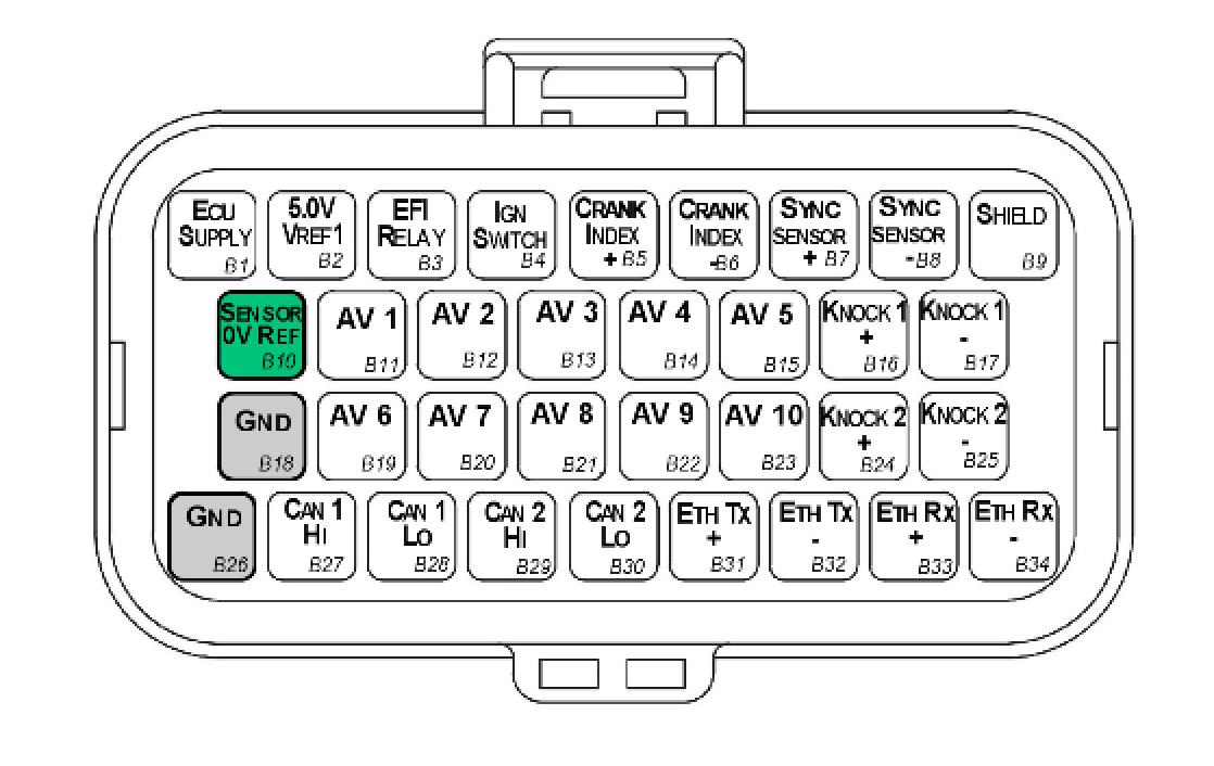
Connector B — TE Superseal 34 Way / Key 1.
3.1 Connector B Wire Colours
| Pin Name | Pin | Description | Colour | Wire Size (sq mm) |
|---|---|---|---|---|
| ECU SUPPLY | B1 | ECU Supply | Red | 0.85 |
| 5V SUPPLY | B2 | Main 5V engine sensor supply (Branched) | Orange | 0.50 |
| EFI RELAY | B3 | Main Relay Control | Pink/Black | 0.50 |
| IGN SWITCH | B4 | Ignition Switch | Red | 0.50 |
| CRANK INDEX + | B5 | Crank Index position sensor Positive | 2 core Shielded Cable (shared with B6) | — |
| CRANK INDEX - | B6 | Crank Index position sensor Negative | 2 core Shielded Cable (shared with B5) | — |
| SYNC SENSOR + | B7 | Sync Sensor Positive | 2 core Shielded Cable (shared with B8) | — |
| SYNC SENSOR - | B8 | Sync Sensor Negative | 2 core Shielded Cable (shared with B7) | — |
| Shield | B9 | Knock/Trigger Shield (White 70mm) | White | 0.50 |
| Sensor Gnd | B10 | Sensor Ground (Branched Cable) | Black | 0.50 |
| AV 1 | B11 | Analog Voltage CH 1 | White | 0.50 |
| AV 2 | B12 | Analog Voltage CH 2 | White | 0.50 |
| AV 3 | B13 | Analog Voltage CH 3 | White | 0.50 |
| AV 4 | B14 | Analog Voltage CH 4 | White | 0.50 |
| AV 5 | B15 | Analog Voltage CH 5 | White | 0.50 |
| KNK 1 + | B16 | Knock Sensor 1 + | 2 core Shielded Cable (shared with B17) | — |
| KNK 1 - | B17 | Knock Sensor 1 - | 2 core Shielded Cable (shared with B16) | — |
| GND | B18 | Power Ground | Black | 0.85 |
| AV 6 | B19 | Analog Voltage CH 6 | White | 0.50 |
| AV 7 | B20 | Analog Voltage CH 7 | White | 0.50 |
| AV 8 | B21 | Analog Voltage CH 8 | White | 0.50 |
| AV 9 | B22 | Analog Voltage CH 9 | White | 0.50 |
| AV 10 | B23 | Analog Voltage CH 10 | White | 0.50 |
| KNK 2 + | B24 | Knock Sensor 2 + | 2 core Shielded Cable (shared with B25) | — |
| KNK 2 - | B25 | Knock Sensor 2 - | 2 core Shielded Cable (shared with B24) | — |
| GND | B26 | Power Ground | Black | 0.85 |
| CAN 1 HI | B27 | Main Engine CAN | White | 0.50 |
| CAN 1 LO | B28 | Main Engine CAN | Green | 0.50 |
| CAN 2 HI | B29 | Auxiliary CAN | White | |
| CAN 2 LO | B30 | Auxiliary CAN | Green | |
| Ethernet TX+ | B31 | Twisted Pair CAT 5E | ||
| Ethernet TX- | B32 | Twisted Pair CAT 5E | ||
| Ethernet RX+ | B33 | Twisted Pair CAT 5E | ||
| Ethernet RX- | B34 | Twisted Pair CAT 5E |
3.2 Pin B10 Sensor Ground Branched Connections
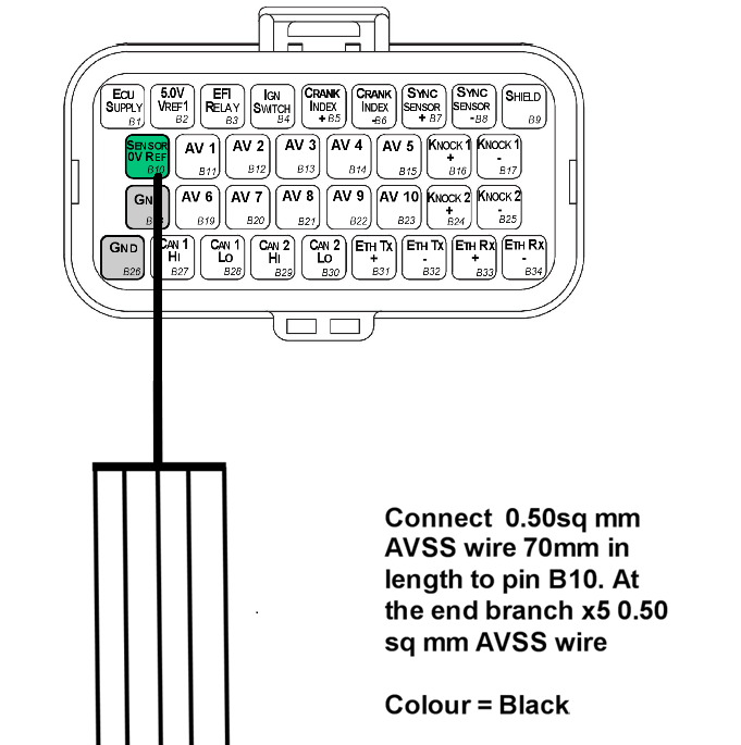
Pin B10 (Sensor Ground) is a branched connection feeding the analog sensor 0V references.
3.3 Pin B2 5V Supply Branched Connections
Pin B2 (5V Supply) is a branched connection feeding the engine sensor 5V supply.
3.4 Crank and Sync Shielded Cable Connections
- Use x1 2-core shielded cable for Pins B5 and B6
- Use x1 2-core shielded cable for Pins B7 and B8
NoteNOTE The individual core colours are not specified but there MUST be at least one different core colour between the Crank Index cable and Sync Sensor cable — i.e. the exact same cables cannot be used for both connections.
3.5 Knock Shielded Cable Connections
- Use x1 2-core shielded cable for Pins B16 and B17
- Use x1 2-core shielded cable for Pins B24 and B25
NoteNOTE The individual core colours are not specified but there MUST be at least one different core colour between the KNK 1 cable and KNK 2 cable — i.e. the exact same cables cannot be used for both connections. Ideally these core colours should also be different to those used in section 3.4.
3.6 Ethernet Sub Harness - Pins B31-B34
See the document “Ethernet to Superseal Loom Specification V1.x”. This sub harness should be plugged into Connector B, Pins B31 → B34.
Appendix A – SL8 ECU Pinout Drawing
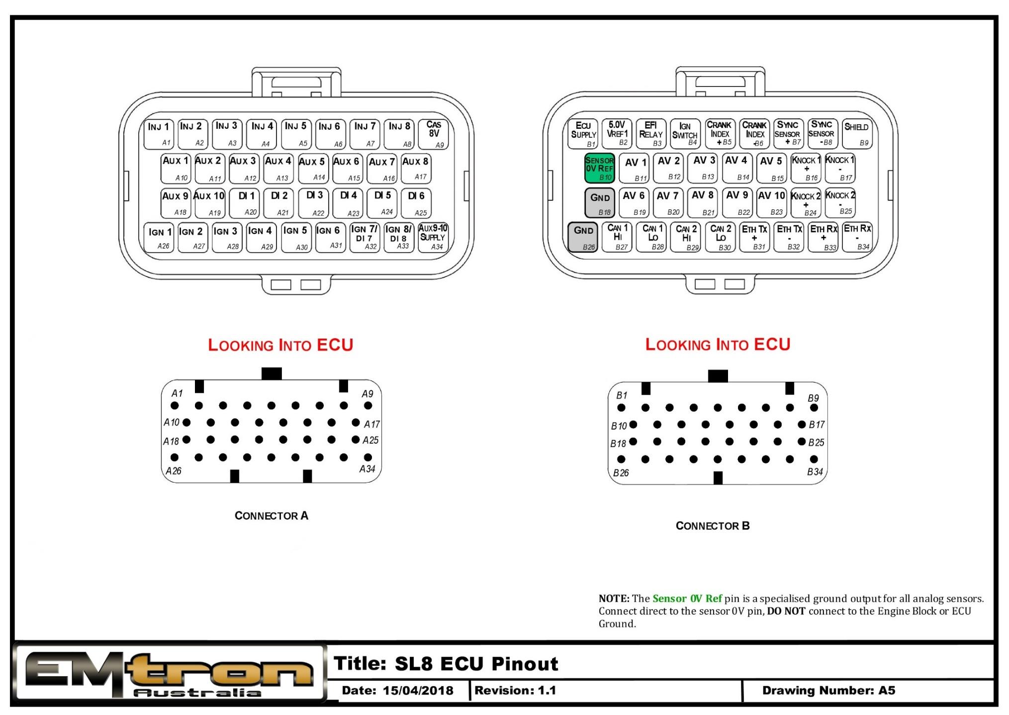
SL8 ECU pinout — Connector A and Connector B, looking into the ECU.
Appendix B – SL6 ECU Pinout Drawing
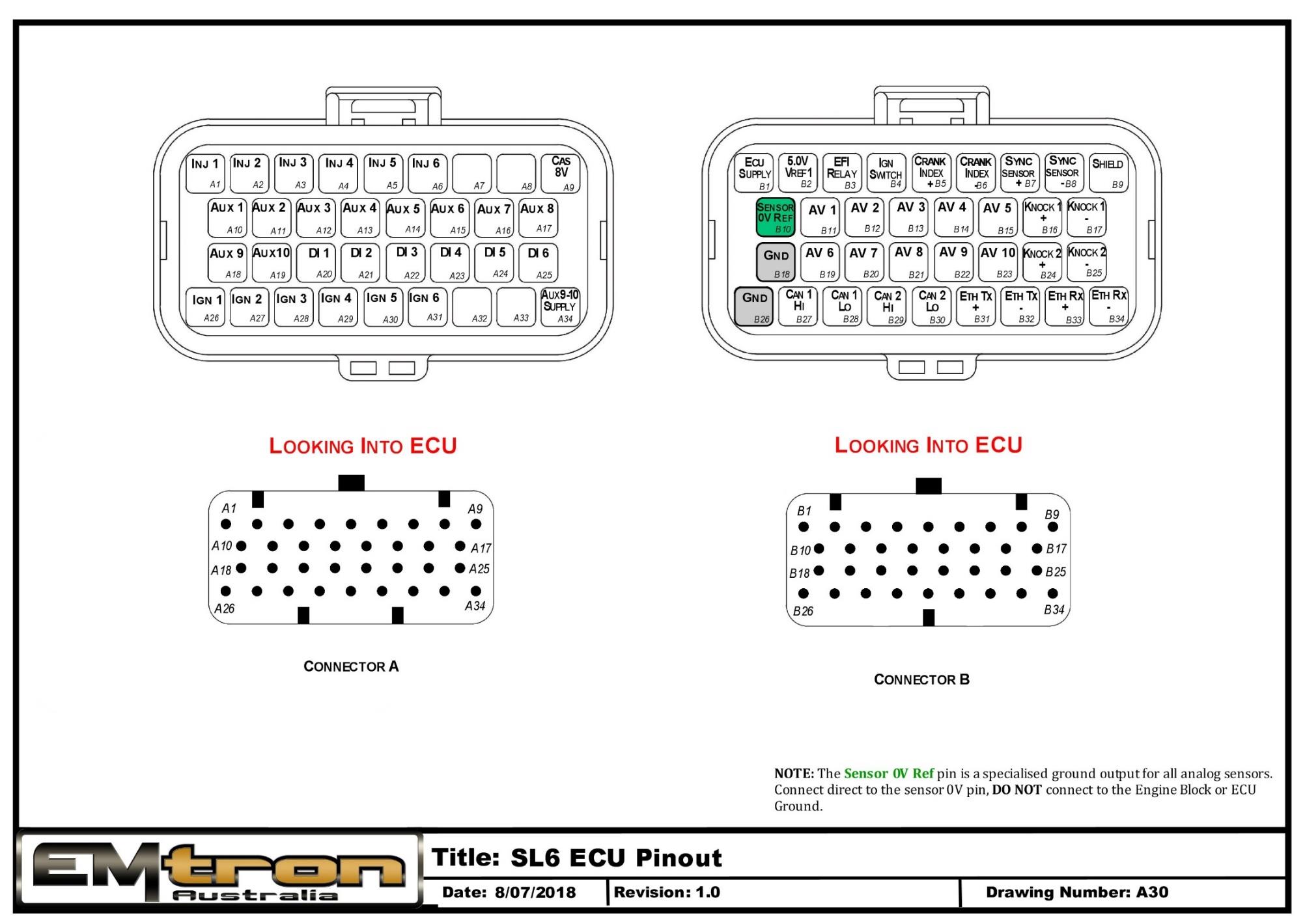
SL6 ECU pinout — Connector A and Connector B, looking into the ECU.
Appendix C – SL4 ECU Pinout Drawing
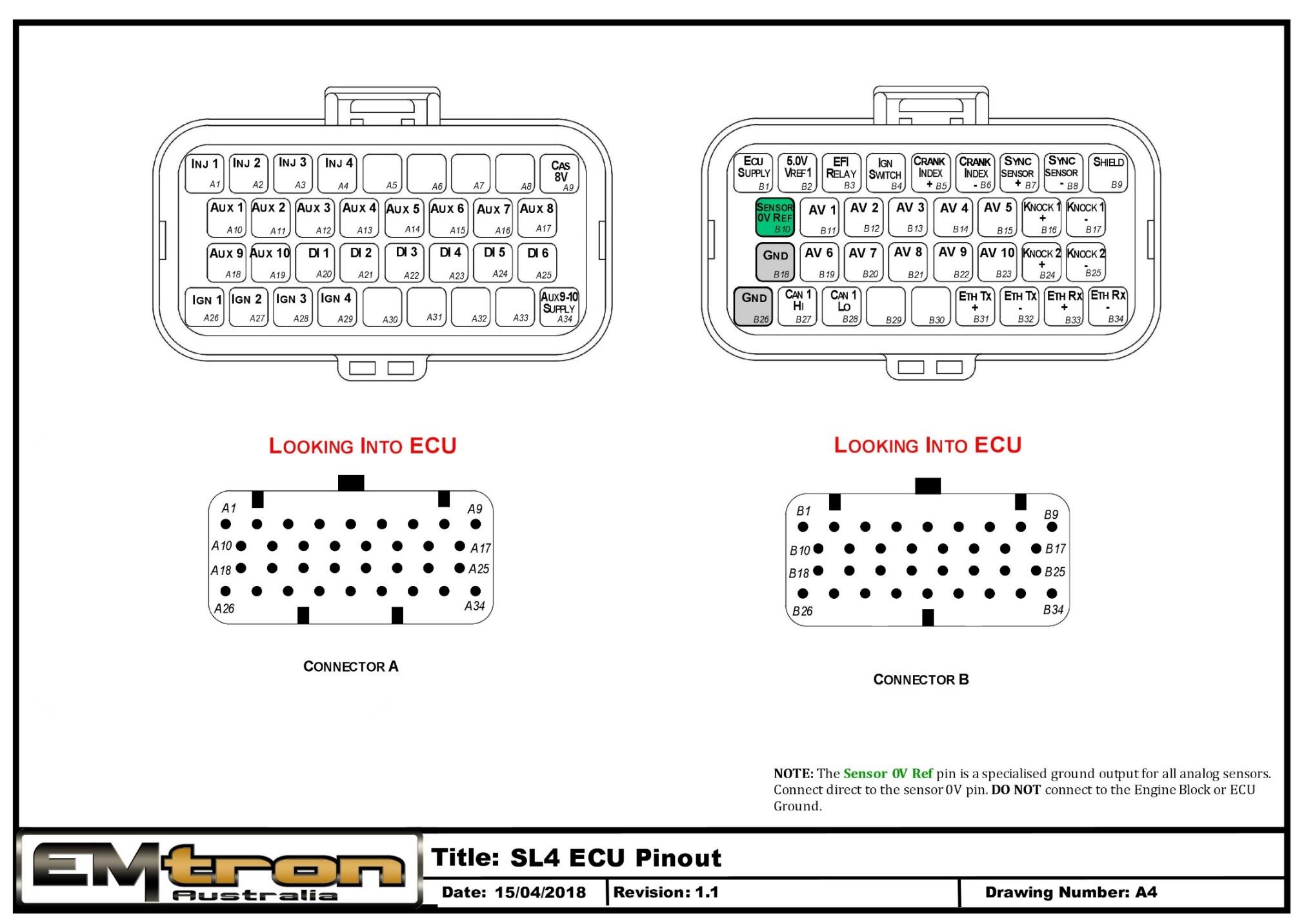
SL4 ECU pinout — Connector A and Connector B, looking into the ECU.
Appendix D – SL Series ECU Wiring
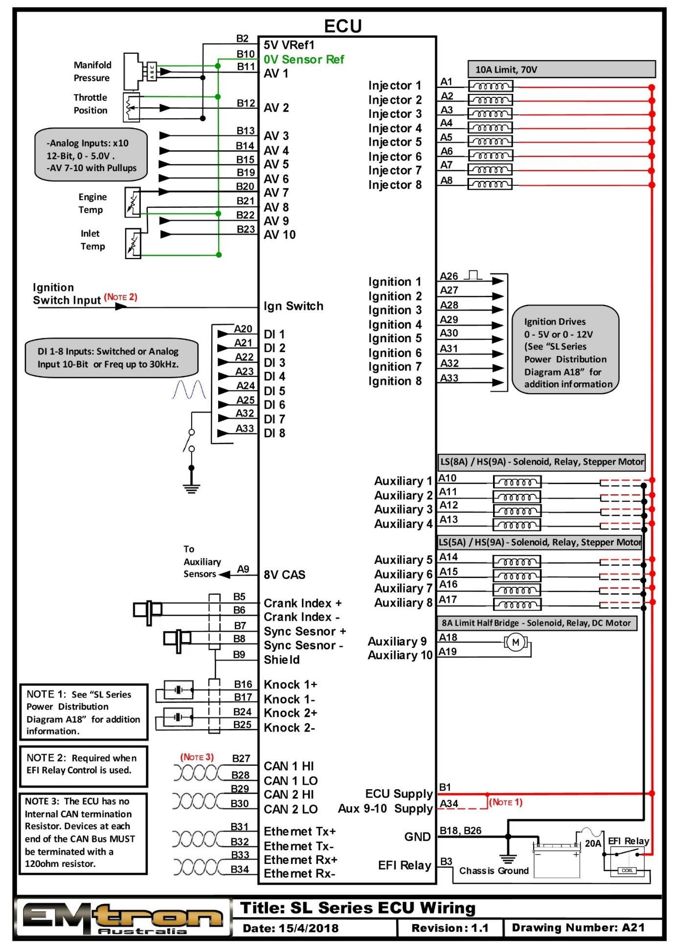
SL Series ECU wiring overview (drawing A21).
Appendix E – SL Series Ethernet Wiring
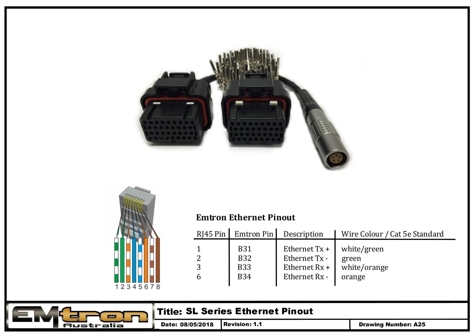
SL Series Ethernet wiring / tuning cable pinout (drawing A25).
SL Series Power Distribution Wiring