SL6 Pin Assignment Template

SL6 Pinout Summary
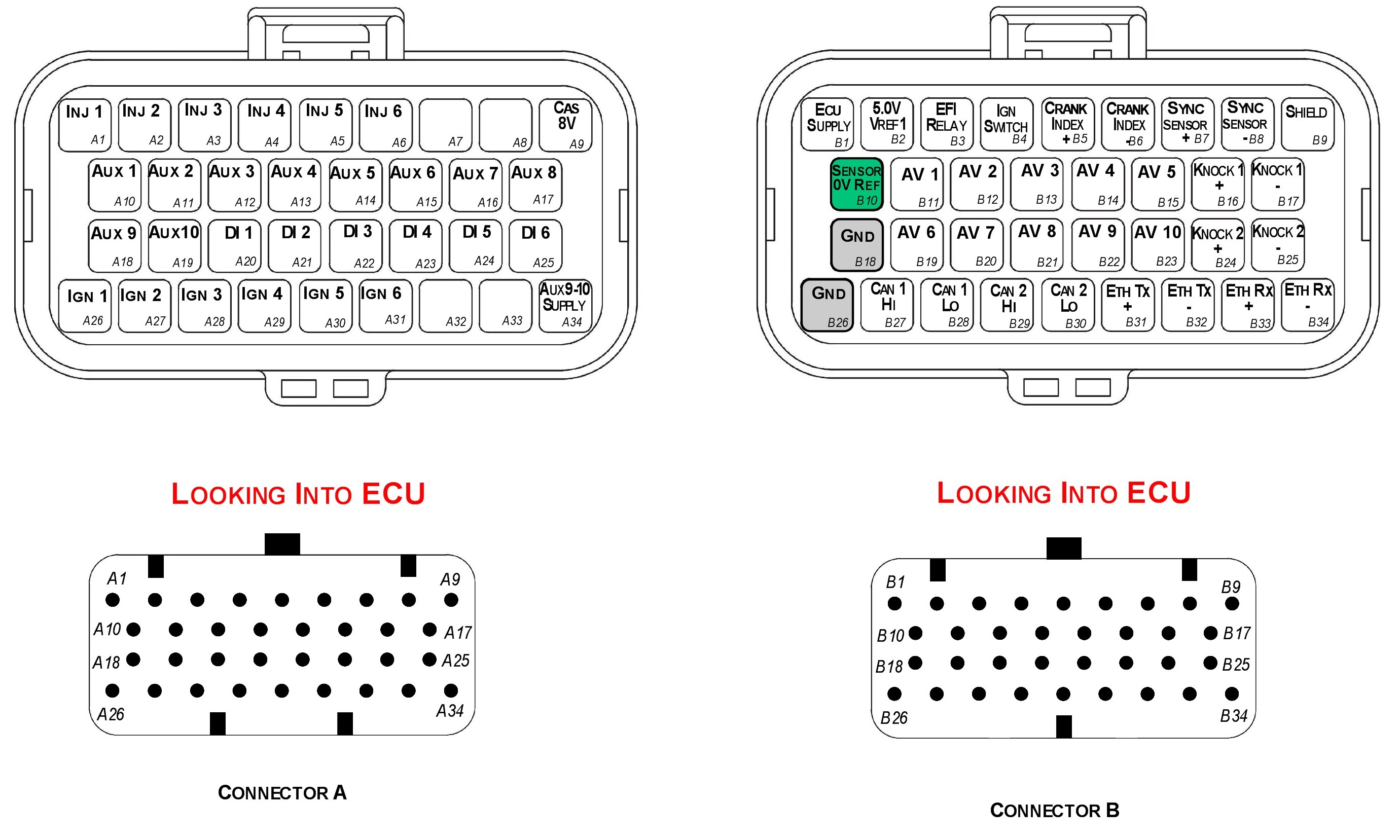
| Pin Name | Pin # | Function | Notes |
|---|---|---|---|
| Inj 1 | A1 | ||
| Inj 2 | A2 | ||
| Inj 3 | A3 | ||
| Inj 4 | A4 | Injector Outputs | 10A Limit, 70V Clamp, |
| Inj 5 | A5 | ||
| Inj 6 | A6 | Auxiliary function control, Ground switch. | |
| 6A Continuous, 10A Limit, 70V Clamp | |||
| Ign 1 | A26 | ||
| Ign 2 | A27 | ||
| Ign 3 | A28 | ||
| Ign 4 | A29 | Ignition Outputs Logic level (TTL) | 35mA or 70mA selectable current drive. Auxiliary function control, Ground switch. |
| Ign 5 | A30 | 1A Continuous, 3A Limit, 39V Clamp | |
| Ign 6 | A31 | ||
| Aux 1 | A10 | Maximum Frequency = 15kHz, Flyback | |
| Aux 2 | A11 | Ground Switch 3A Continuous, 8A Limit | |
| Aux 3 | A12 | Auxiliary Outputs | 2k2 Pullup to ECU Supply |
| Aux 4 | A13 | ||
| Aux 5 | A14 | Maximum Frequency = 15kHz, , Flyback | |
| Aux 6 | A15 | Ground Switch 2A Continuous, 5A Limit | |
| Aux 7 | A16 | Auxiliary Outputs | High Switch 5A Continuous, 8A Limit |
| Aux 8 | A17 | 2k2 Pullup to ECU Supply | |
| Aux 9 | A18 | Maximum Frequency = 15kHz | |
| Aux 10 | A19 | Auxiliary Outputs | Half Bridge 5A Continuous and 8A Limit |
| AV1 | B11 | ||
| AV 2 | B12 | ||
| AV 3 | B13 | ||
| AV 4 | B14 | Analog Inputs | 12 Bit Resolution. 0.0V – 5.0V range |
| AV 5 | B15 | ||
| AV 6 | B19 | ||
| AV 7 | B20 | ||
| AV 8 | B21 | Analog Inputs | 12 Bit Resolution. 0.0V – 5.0V range |
| AV 9 | B22 | Switchable 1k pullup to 5V | |
| AV 10 | B23 | ||
| DI 1 | A20 | ||
| DI 2 | A21 | Frequency range from 0.0Hz up the 30kHz | |
| DI 3 | A22 | Switchable 4k7 pullup to 10V | |
| DI 4 | A23 | Digital Inputs | Analog Input range 0.0V - 15.0V (10 Bit) |
| DI 5 | A24 | Adjustable Sw Thresholds on Analog Inputs | |
| DI 6 | A25 | Freq Inputs - DI 1-4 Adjustable Thresholds | |
| DI 7 | A33 | Freq Inputs - DI 5-8 Fixed Thresholds(1.8V) | |
| DI 8 | A34 | ||
| Knock 1 + | B16 | Knock Sensor 1 Input +ve | |
| Knock 1 - | B17 | Knock Sensor 1 Input –ve | |
| Knock 2 + | B24 | Knock Sensor 2 Input +ve | |
| Knock 2 - | B25 | Knock Sensor 2 Input –ve | |
| Crank Index + | B5 | Crank Sensor Input +ve | Switchable 4k7 pullup |
| Crank Index - | B6 | Crank Sensor Input –ve | |
| Sync Sensor + | B7 | Sync Sensor Input +ve | Switchable 4k7 pullup |
| Sync Sensor - | B8 | Sync Sensor Input –ve | |
| CAN 1 H | B27 | CAN Communications | Not terminated. |
| CAN 1 L | B28 | CAN Communications | |
| CAN 2 H | B29 | CAN Communications | Not terminated. |
| CAN 2 L | B30 | CAN Communications | |
| ETH Tx + | B31 | Ethernet Communications | |
| ETH Tx - | B32 | Ethernet Communications | |
| ETH Rx + | B33 | Ethernet Communications | |
| ETH Rx - | B34 | Ethernet Communications | |
| ECU Supply | B1 | ECU 14V Supply | 22V, 10A |
| 5V Supply | B2 | 5V sensor supply | 250mA current source |
| 8V CAS | A9 | 8V sensor supply | 400mA current source |
| AUX 9-10 Supply | A34 | Supply for Auxiliary Channel 9-10 half bridge drivers | 22V, 10A. Connect to ECU Supply in non-DBW applications. Otherwise connect to DBW relay output |
| IGN SWITCH | B4 | Ignition switch input | Analog Input range 0.0V - 15.0V |
| EFI Relay | B3 | EFI Main relay control | 22V 250mA, ground switching |
| GND | B18 | ECU Ground | 22V, 10A |
| GND | B26 | ECU Ground | 22V, 10A |
| Sensor 0V Ref | B10 | 0V Reference for analog sensors | 22V, 1A protected |
| Shield | B9 | Shield for Crank/Knock Cables | 22V, 1A protected |
Important Notes
Analog Sensor 0V Reference (Pin B10)
This pin should be connected directly to the 0V (Ground) pin on any low current analog sensor, for example Pressure or Temperature.
- DO NOT connect the ECU pin B10 directly to the Engine Block or ECU Ground. These are dedicated and specialised ground outputs for all analog channels and should be connected directly to the sensor.
- DO NOT connect frequency-based sensors to these pins; for example, an Ethanol content sensor. The sensor 0V pin should be connected to the ECU ground.
Half Bridge Driver Power Supply Input (Pin A34)
Pin A34 is a dedicated power supply for Auxiliary Channels 9-10. Power must be supplied to this pin for these channels to operate correctly. In non-DBW (Drive by Wire) applications the ECU Supply power can be shared, assuming the wire gauge has a sufficient rating for the current demand. In DBW applications power to this pin MUST come from an ECU controlled DBW Relay.