SL6 Pinout
Pin Descriptions
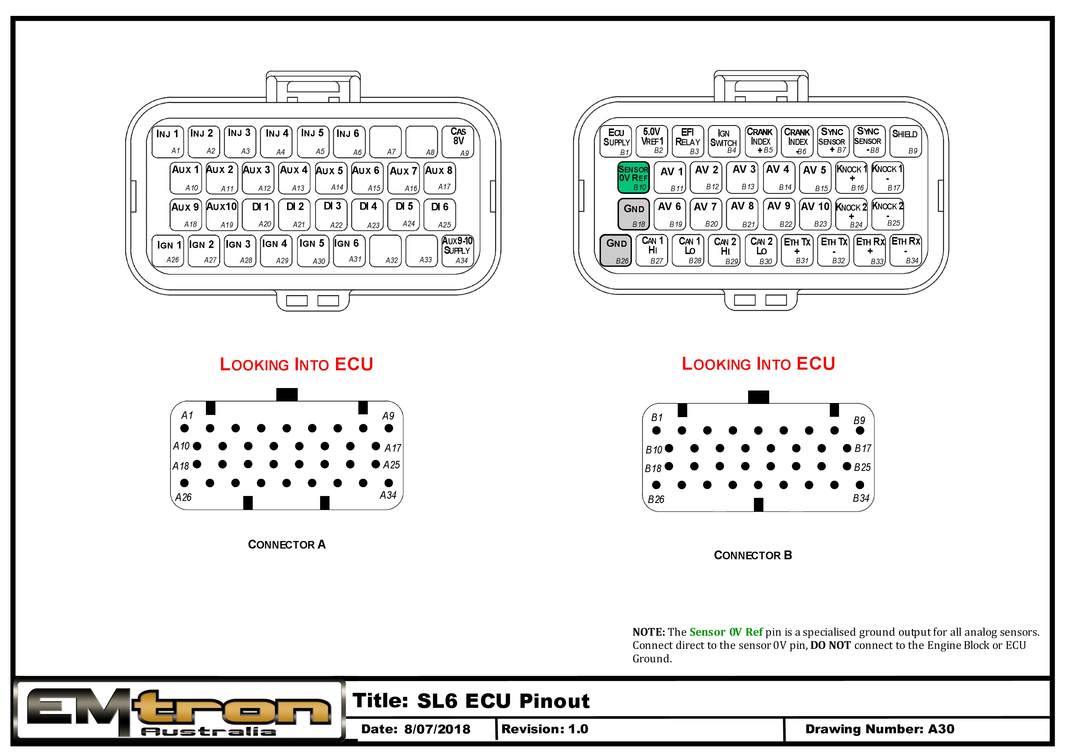
| Connector A: Injection/Ignition/Auxiliary Outputs (15.0A Max continuous current - wire gauge dependant) |
|---|
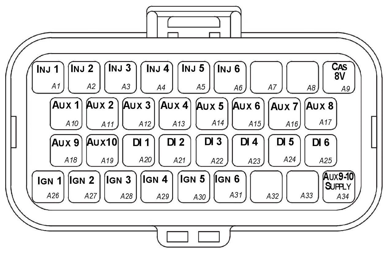
Looking into ECU connector
| Pin | Channel Name | Pin | Channel Name |
|---|---|---|---|
| A1 | Injection Channel 1 | A18 | Auxiliary Output 9 |
| A2 | Injection Channel 2 | A19 | Auxiliary Output 10 |
| A3 | Injection Channel 3 | A20 | Digital Input 1 |
| A4 | Injection Channel 4 | A21 | Digital Input 2 |
| A5 | Injection Channel 5 | A22 | Digital Input 3 |
| A6 | Injection Channel 6 | A23 | Digital Input 4 |
| A7 | NC | A24 | Digital Input 5 |
| A8 | NC | A25 | Digital Input 6 |
| A9 | Sensor Supply 8V | A26 | Ignition Channel 1 |
| A10 | Auxiliary Output 1 | A27 | Ignition Channel 2 |
| A11 | Auxiliary Output 2 | A28 | Ignition Channel 3 |
| A12 | Auxiliary Output 3 | A29 | Ignition Channel 4 |
| A13 | Auxiliary Output 4 | A30 | Ignition Channel 5 |
| A14 | Auxiliary Output 5 | A31 | Ignition Channel 6 |
| A15 | Auxiliary Output 6 | A32 | NC |
| A16 | Auxiliary Output 7 | A33 | NC |
| A17 | Auxiliary Output 8 | A34 | Auxiliary Output 9-10, 14V Supply |
| Connector B: Signal/Power/Communications/Triggers/Knock (15.0A Max continuous current - wire gauge dependant) |
|---|
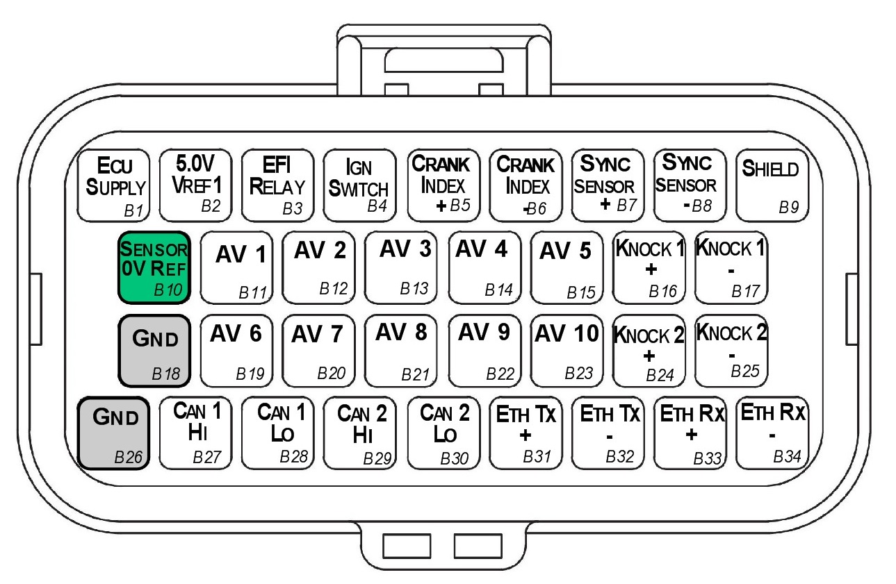
Looking into ECU connector
| Pin | Channel Name | Pin | Channel Name |
|---|---|---|---|
| B1 | ECU 14V Supply | B18 | ECU Ground |
| B2 | Sensor Supply Vref1: 5.0V | B19 | Analog Input Channel 6 |
| B3 | EFI Relay Output (Low Side 200mA) | B20 | Analog Input Channel 7 |
| B4 | Ignition Switch Input | B21 | Analog Input Channel 8 |
| B5 | Crank Index Sensor + | B22 | Analog Input Channel 9 |
| B6 | Crank Index Sensor - | B23 | Analog Input Channel 10 |
| B7 | Sync Sensor + | B24 | Knock 2 + |
| B8 | Sync Sensor - | B25 | Knock 2 - |
| B9 | Shield (Crank/Sync/ Knock) | B26 | ECU Ground |
| B10 | Analog Sensor 0V Reference | B27 | CAN 1H |
| B11 | Analog Input Channel 1 | B28 | CAN 1L |
| B12 | Analog Input Channel 2 | B29 | NC |
| B13 | Analog Input Channel 3 | B30 | NC |
| B14 | Analog Input Channel 4 | B31 | Ethernet Tx + |
| B15 | Analog Input Channel 5 | B32 | Ethernet Tx - |
| B16 | Knock 1 + | B33 | Ethernet Rx + |
| B17 | Knock 1 - | B34 | Ethernet Rx - |
Important Notes
Analog Sensor 0V Reference (Pin B10)
This pin should be connected directly to the 0V (Ground) pin on any low current analog sensor, for example Pressure or Temperature.
- DO NOT connect the ECU pin B10 directly to the Engine Block or ECU Ground. These are dedicated and specialised ground outputs for all analog channels and should be connected directly to the sensor.
- DO NOT connect frequency-based sensors to these pins; for example, an Ethanol content sensor. The sensor 0V pin should be connected to the ECU ground.
Half Bridge Driver Power Supply Input (Pin A34)
Pin A34 is a dedicated power supply for Auxiliary Channels 9-10. Power must be supplied to this pin for these channels to operate correctly. In non-DBW (Drive by Wire) applications the ECU Supply power can be shared, assuming the wire gauge has a sufficient rating for the current demand. In DBW applications power to this pin MUST come from an ECU controlled DBW Relay.