Gear Tooth Sensor Datasheet
1.0 Description
The Emtron Gear Tooth Sensor is a state-of-the-art flange mounted Hall Effect sensor designed for use in applications where ferrous edge detection / near zero speed sensing is required. Being of a single Hall design, the sensor is immune to alignment issues allowing unlimited mounting positions.
Features & Benefits:
- From near zero speed up to 15 kHz sensing capability
- Capable of operating up to 150ºC
- Plastic flange mount-housing
- Resistant to fuels, solvents, and lubricants associated with vehicles
- RoHS compliant
- Sealed design exceeds IEC60529 IP67 standard for immersion
- Easily customizable connector orientation
- Typical air gap of 1.5 mm (with recommended target type; see drawing)
- Mating connector – Delphi 12162280 (Type 102)
- Mating connector pin – Delphi PN: 12124075 or 12124076
Typical Applications:
- Engine Speed Sensor (both Crank & Sync)
- Transmission Speed Sensor
- Wheel Speed Sensor
- Tail Shaft Speed Sensor
2.0 Specifications
Electrical Specifications
| Parameter | Value |
|---|---|
| Operating Voltage Range | 5–30 VDC |
| Supply Current | 6mA max |
| Output Saturation Voltage | 600 mV max |
| Output Current | 25 mA max |
| Operating Temperature | -40° to 150ºC* |
| Storage Temperature Range | -55° to 150ºC |
| Output Rise time | 10µS |
| Output Fall time | 10µS |
| Bulk Current Injection | SAE J1113-4 (250kHz to 500MHz; 100mA/m) |
| Conduction and Coupling | SAE J1113-12 (±200V) |
| Electronic Discharge | SAE J1113-13 (±15kV) |
| Radiated Immunity | SAE J1113-21 (10kHz to 18GHz; 200 V/m) |
| Immunity to Magnetic Fields | SAE J1113-22 (600µT AC Field; 5Hz to 2kHz; .2mT & 1mT DC Field) |
| Radiated Emissions | SAE J1113-23 |
| Immunity to AC Fields | SAE J1113-25 (15kV/m) |
| Radiated Emissions | SAE J1113-41 (Class 4) |
| Maximum Speed | 15kHz |
*For continuous operation at 150°C supply voltage should be limited to 5.5V max.
Environmental Specifications
| Parameter | Value |
|---|---|
| Water Immersion | IEC60529 IP67 |
| Dust, Sand and Gravel Bombardment | SAE J400 JUN80 |
| Vibration | Sinusoidal vibration max 15g’s from 40 to 2000 Hz |
| Mechanical Shock | 18 shocks at 50g’s 11ms per Mil Std 202F (94.4C) |
Mechanical Specifications
| Parameter | Value |
|---|---|
| Air gap | 1.5 mm |
| Max Installation Torque | 50 in-lbs (for a 1/4 - 20 bolt or M6 X 1) |
2.1 Dimensions
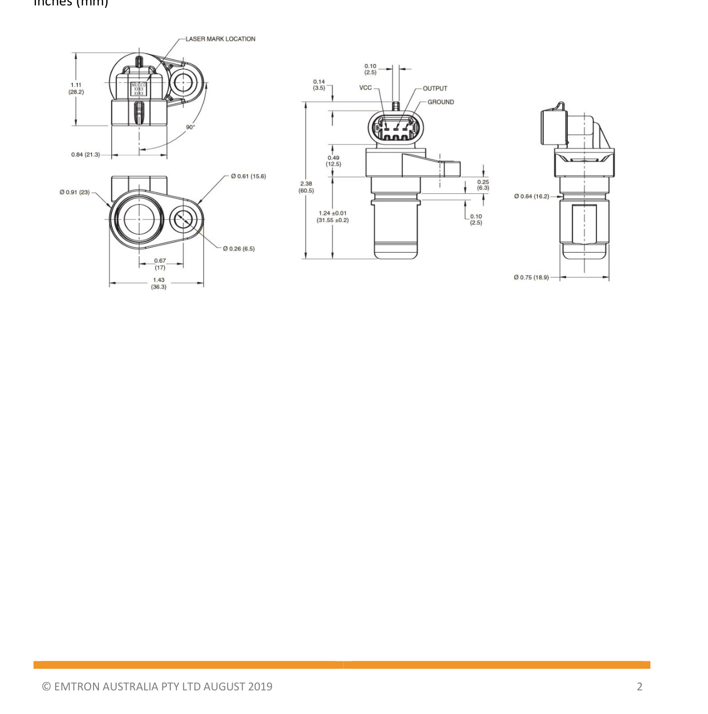
Gear Tooth Sensor dimensions and connector wiring — inches (mm).
2.2 Installation
For best results, targets should be produced from low carbon cold rolled steel. Other factors that influence sensor performance include gear tooth height and width, space between teeth, shape of the teeth and thickness of the target.
As a general guideline, consider a target within the following minimum parameters.
| Tooth Height (Min) | Tooth Width (Min) | Distance Between Teeth (Min) | Target Thickness (Min) |
|---|---|---|---|
| 0.200" (5.0mm) | 0.100" (2.5mm) | 0.400" (10mm) | 0.250" (6.35mm) |
2.3 Wiring
| Plug Pin | Sensor Pin | ECU Connection |
|---|---|---|
| A | VCC | CAS 8V or 5V VRef |
| B | OUTPUT | Available Crank / Sync / Digital Input |
| C | GROUND | GND (Do not connect to 0V Ref sensor ground) |
3.0 Ordering Information
| Product | Part Number |
|---|---|
| Gear Tooth Sensor (Sensor Only) | 52019-8 |
| Gear Tooth Sensor Kit (Includes Connector Kit) | 52019-811 |
| Gear Tooth Sensor Connector Kit | N/A |