Subsections of Datasheets
MAP Sensor 1.0 Bar Datasheet
1.0 Description
The Emtron 1.0 Bar MAP Sensor uses a state-of-the-art piezoresistive transducer from NXP Semiconductors. It is highly accurate, providing a high level analog output signal that is proportional to the applied pressure.
1.1 Features
- Genuine NXP Sensor
- Pressure Range: 15kPa to 115kPa
- Supply Voltage: 4.75 to 5.25 Volts DC
- Current Supply 6.0mA
- Protective Silicone Gel prevents sensor damage from airborne contaminates like oil, petrol and methanol.
- Fully calibrated and temperature compensated from -40 DegC to +125 DegC
- Response time 1ms
- Compact Design
- Stainless Steel 303 body for durability then coated in black nickel for superior abrasion resistance
- Fully potted for a waterproof seal and resistance to shock and vibration
- 1/8 NPT Thread
- Deutsch 3 Way Connector (mating end also supplied)
1.2 Dimensions
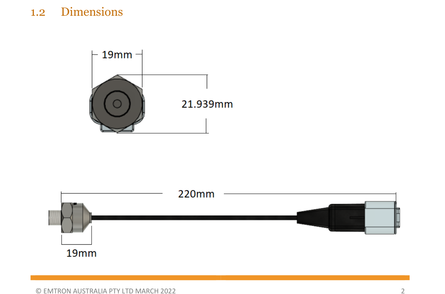
MAP Sensor 1.0 Bar dimensions.
2.2 Installation
Fit to a prepared 1/8 NPT tapped port. Screw the MAP sensor finger tight into the port then tighten with a spanner 1.5 to 3.0 turns past finger tight. Do not exceed 16Nm (12 lbs/ft).
An anaerobic thread sealant may be used sparingly. Avoid excessive use to prevent sensor blockage/failure.
WarningWARNING Do not back off an installed MAP sensor to achieve a desired alignment. Loosening the installed MAP sensor will compromise the seal and lead to potential leakage or failure.
2.3 Wiring
Deutsch 3 Way Connector Pinout
| Pin | Function |
|---|---|
| 1 | Sensor 0V ref |
| 2 | Signal |
| 3 | 5.0V |
- Connect the MAP Sensor 0V (Pin 1) to the ECU Sensor 0V Reference pin (Sensor Ground). DO NOT connect the MAP Sensor 0V directly to the ECU ground or engine block.
- Connect the MAP Sensor Signal to an available Analog Voltage input or Digital input.
- Connect the MAP Sensor 5.0V to an available 5.0V VRef source which can be referenced in the Emtune software for ratiometric correction.
2.4 Calibration
Transfer Function: Vout = Sensor-Supply × (0.009 × P − 0.095)
Sensor-Supply allows for ratiometric correction. Set to 5.000V when not required.
- P = 115kPa: Vout = 5.00 × (0.009 × 115.0 − 0.095) = 4.700V
- P = 15.0kPa: Vout = 5.00 × (0.009 × 15.0 − 0.095) = 0.200V
| Voltage (V) | Pressure (kPa) |
|---|---|
| 0.200 | 15.0 |
| 4.700 | 115.0 |
This calibration option is available from Emtune. Select the “Emtron 1.0 Bar” option from the Predefined Calibration list on any Analog Channel Input.
Filter Settings
- Filter Setting Minimum = 0 (OFF)
- Filter Setting Maximum = 50
- Recommended Filter Range = 15 - 25
NoteNB This setting is heavily dependent on engine setup and the stability of the MAP signal at idle. Engines with large overlapping camshafts, for example, will most likely need a larger filter value to achieve a more stable MAP signal.
2.5 Ordering Information
| Product | Part Number |
|---|---|
| Emtron MAP Sensor 1.0 Bar | 1301-10A |
MAP Sensor 4.0 Bar Datasheet
1.0 Description
The Emtron 4.0 Bar MAP Sensor uses a state-of-the-art piezoresistive transducer from NXP Semiconductors. It is highly accurate, providing a high level analog output signal that is proportional to the applied pressure.
1.1 Features
- Genuine NXP Sensor
- Pressure Range: 20kPa to 400kPa
- Supply Voltage: 4.75 to 5.25 Volts DC
- Current Supply 6.0mA
- Protective Silicone Gel prevents sensor damage from airborne contaminates like oil, petrol and methanol.
- Fully calibrated and temperature compensated from -40 DegC to +125 DegC
- Response time 1ms
- Compact Design
- Stainless Steel 303 body for durability then coated in black nickel for superior abrasion resistance
- Fully potted for a waterproof seal and resistance to shock and vibration
- 1/8 NPT Thread
- Deutsch 3 Way Connector (mating end also supplied)
1.2 Dimensions
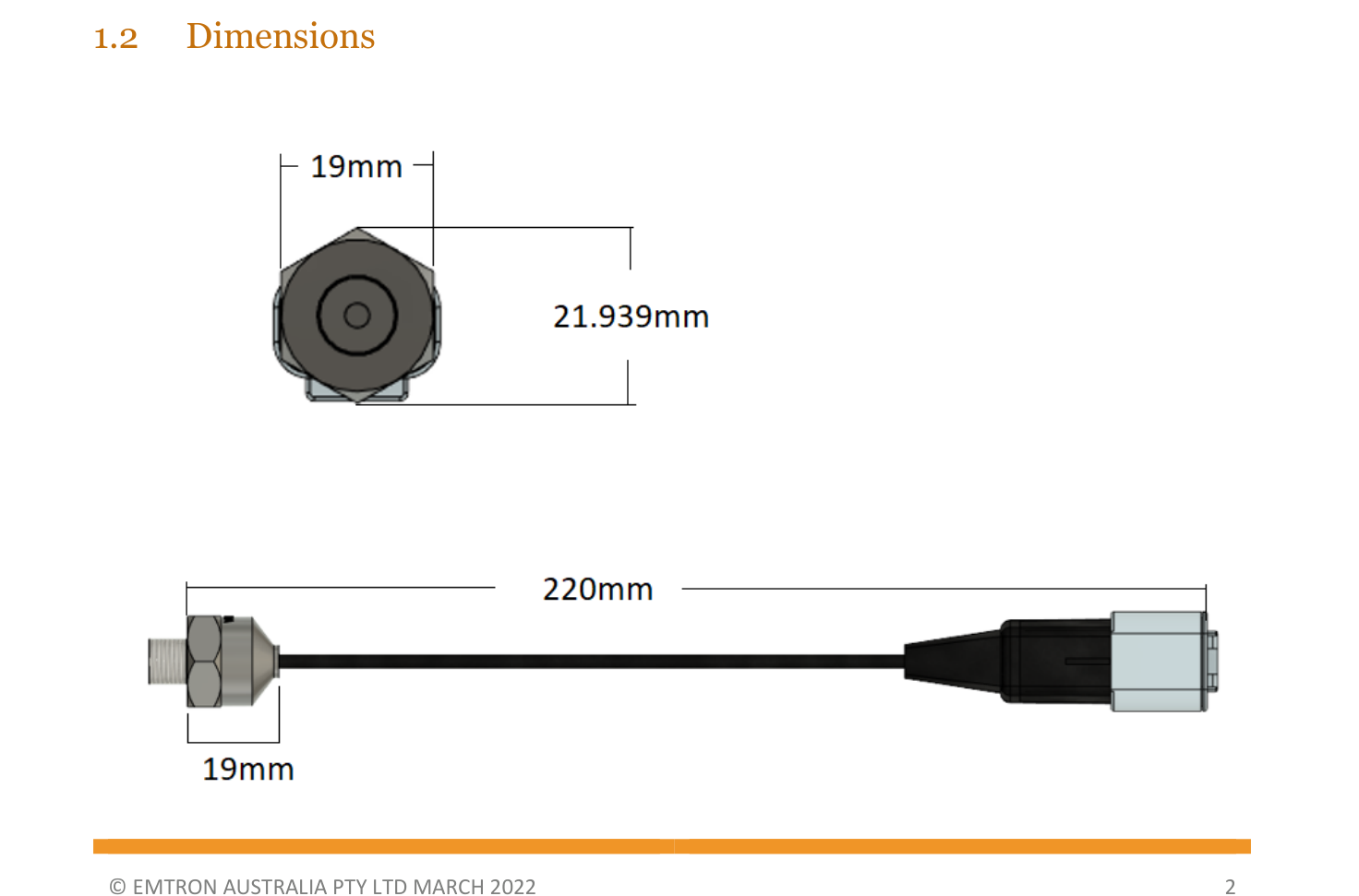
MAP Sensor 4.0 Bar dimensions.
2.2 Installation
Fit to a prepared 1/8 NPT tapped port. Screw the MAP sensor finger tight into the port then tighten with a spanner 1.5 to 3.0 turns past finger tight. Do not exceed 16Nm (12 lbs/ft).
An anaerobic thread sealant may be used sparingly. Avoid excessive use to prevent sensor blockage/failure.
WarningWARNING Do not back off an installed MAP sensor to achieve a desired alignment. Loosening the installed MAP sensor will compromise the seal and lead to potential leakage or failure.
2.3 Wiring
Deutsch 3 Way Connector Pinout
| Pin | Function |
|---|---|
| 1 | Sensor 0V ref |
| 2 | Signal |
| 3 | 5.0V |
- Connect the MAP Sensor 0V (Pin 1) to the ECU Sensor 0V Reference pin (Sensor Ground). DO NOT connect the MAP Sensor 0V directly to the ECU ground or engine block.
- Connect the MAP Sensor Signal to an available Analog Voltage input or Digital input.
- Connect the MAP Sensor 5.0V to an available 5.0V VRef source which can be referenced in the Emtune software for ratiometric correction.
2.4 Calibration
Transfer Function: Vout = Sensor-Supply × (0.002421 × P − 0.00842)
Sensor-Supply allows for ratiometric correction. Set to 5.000V when not required.
- P = 400kPa: Vout = 5.00 × (0.002421 × 400.0 − 0.00842) = 4.800V
- P = 20.0kPa: Vout = 5.00 × (0.002421 × 20.0 − 0.00842) = 0.200V
| Voltage (V) | Pressure (kPa) |
|---|---|
| 0.200 | 20.0 |
| 4.800 | 400.0 |
This calibration option is available from Emtune. Select the “Emtron 4.0 Bar” option from the Predefined Calibration list on any Analog Channel Input.
Filter Settings
- Filter Setting Minimum = 0 (OFF)
- Filter Setting Maximum = 50
- Recommended Filter Range = 15 - 25
NoteNB This setting is heavily dependent on engine setup and the stability of the MAP signal at idle. Engines with large overlapping camshafts, for example, will most likely need a larger filter value to achieve a more stable MAP signal.
2.5 Ordering Information
| Product | Part Number |
|---|---|
| Emtron MAP Sensor 4.0 Bar | 1301-40A |
MAP Sensor 100psi Datasheet
1.0 Description
The Emtron 100psi MAP Sensor uses a state-of-the-art piezoresistive transducer from Bourns Semiconductors. It is highly accurate, providing a high level analog output signal that is proportional to the applied pressure.
1.1 Features
- Genuine Bourns BPX130 series sensor
- Pressure Range: 0kPa to 689.5kPa
- Supply Voltage: 4.50 to 5.50 Volts DC
- Current Supply 10.0mA
- Compatible with harsh media – air, water, oil, petrol and methanol.
- Fully calibrated and temperature compensated from -40 DegC to +150 DegC
- Response time 1ms
- Compact Design
- Stainless Steel 303 body for durability then coated in black nickel for superior abrasion resistance
- Fully potted for a waterproof seal and resistance to shock and vibration
- 1/8 NPT Thread
- Deutsch 3 Way Connector (mating end also supplied)
1.2 Dimensions
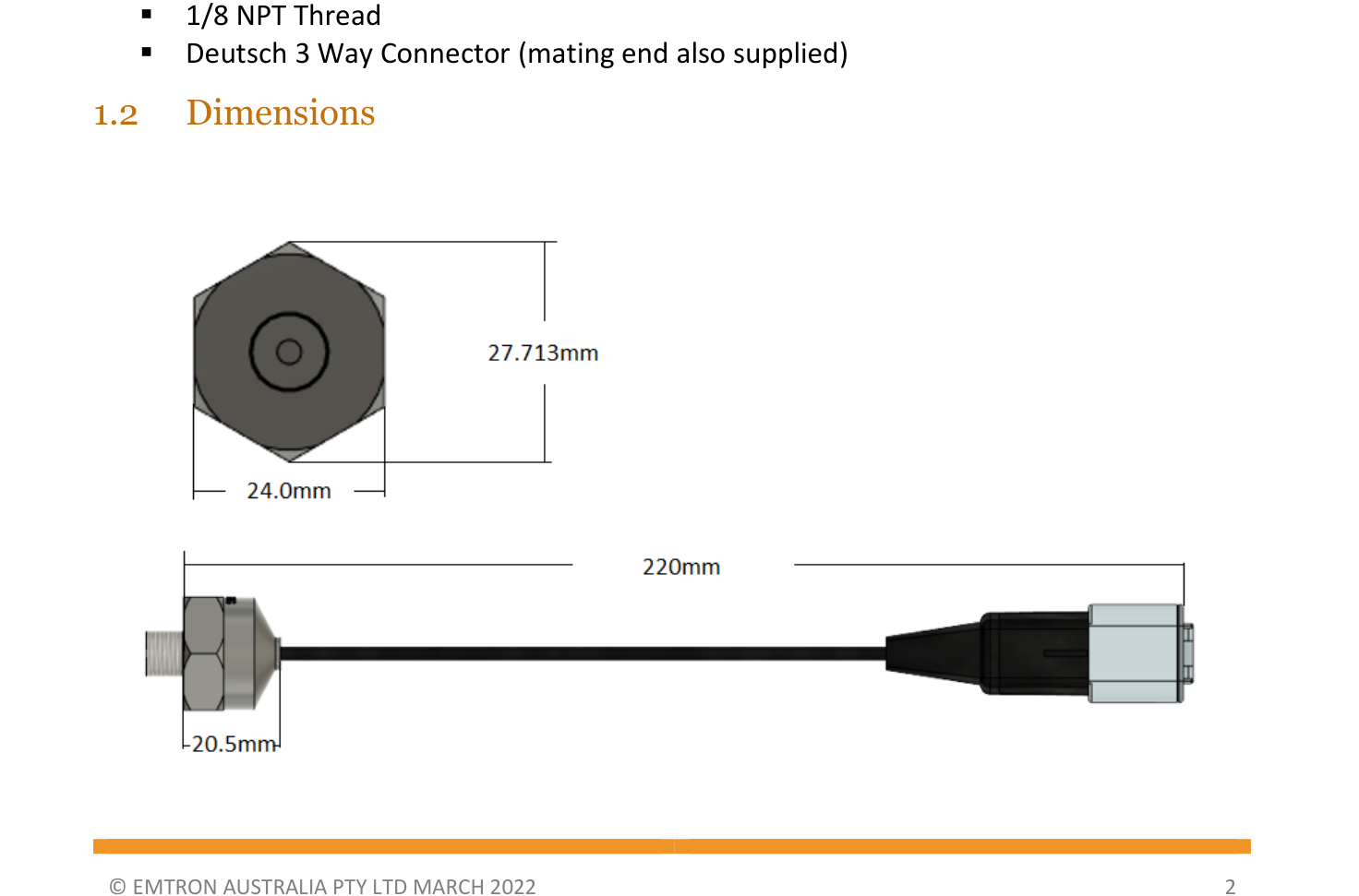
MAP Sensor 100psi dimensions.
2.2 Installation
Fit to a prepared 1/8 NPT tapped port. Screw the MAP sensor finger tight into the port then tighten with a spanner 1.5 to 3.0 turns past finger tight. Do not exceed 16Nm (12 lbs/ft).
An anaerobic thread sealant may be used sparingly. Avoid excessive use to prevent sensor blockage/failure.
WarningWARNING Do not back off an installed MAP sensor to achieve a desired alignment. Loosening the installed MAP sensor will compromise the seal and lead to potential leakage or failure.
2.3 Wiring
Deutsch 3 Way Connector Pinout
| Pin | Function |
|---|---|
| 1 | Sensor 0V ref |
| 2 | Signal |
| 3 | 5.0V |
- Connect the MAP Sensor 0V (Pin 1) to the ECU Sensor 0V Reference pin (Sensor Ground). DO NOT connect the MAP Sensor 0V directly to the ECU ground or engine block.
- Connect the MAP Sensor Signal to an available Analog Voltage input or Digital input.
- Connect the MAP Sensor 5.0V to an available 5.0V VRef source which will be referenced for ratiometric correction in the Emtune software.
2.4 Calibration
Sensor-Supply allows for ratiometric correction. Set to 5.000V when not required. The output is linear between the endpoints below.
| Voltage (V) | Pressure (kPa) |
|---|---|
| 0.500 | 0 |
| 4.500 | 689.5 |
This calibration option is available from Emtune. Select the “Emtron 100psi” option from the Predefined Calibration list on any Analog Channel Input.
Filter Settings
- Filter Setting Minimum = 0 (OFF)
- Filter Setting Maximum = 50
- Recommended Filter Range = 15 - 25
NoteNB This setting is heavily dependent on engine setup and the stability of the MAP signal at idle. Engines with large overlapping camshafts, for example, will most likely need a larger filter value to achieve a more stable MAP signal.
2.5 Ordering Information
| Product | Part Number |
|---|---|
| Emtron MAP Sensor 100 Psi | 1606-100A |
300psi Pressure Sensor Datasheet
1.0 Description
The Emtron 300psi Gauge Pressure Sensor uses a state-of-the-art piezoresistive transducer from Bourns Semiconductors. It is highly accurate, providing a high level analog output signal that is proportional to the applied pressure.
1.1 Features
- Genuine Bourns BPX130 series sensor
- Pressure Range: 0kPa to 2068.4kPa
- Supply Voltage: 4.50 to 5.50 Volts DC
- Current Supply 10.0mA
- Compatible with harsh media – air, water, oil, petrol and methanol.
- Fully calibrated and temperature compensated from -40 DegC to +150 DegC
- Response time 1ms
- Compact Design
- Stainless Steel 303 body for durability then coated in black nickel for superior abrasion resistance
- Fully potted for a waterproof seal and resistance to shock and vibration
- 1/8 NPT Thread
- Deutsch 3 Way Connector (mating end also supplied)
1.2 Dimensions
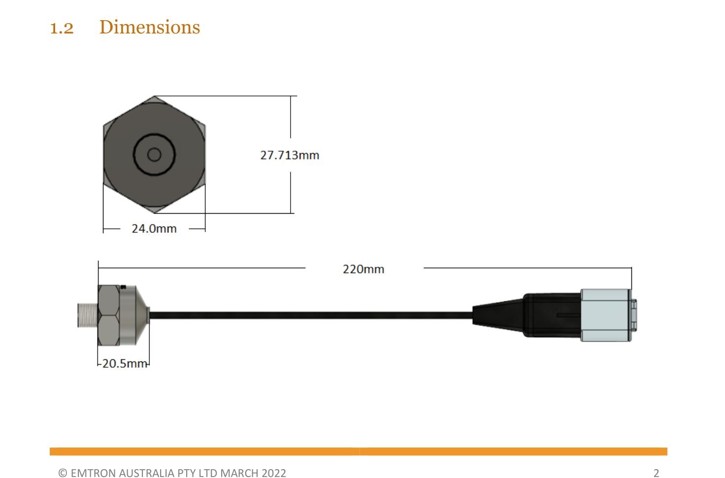
300psi Pressure Sensor dimensions.
2.2 Installation
Fit to a prepared 1/8 NPT tapped port. Screw the pressure sensor finger tight into the port then tighten with a spanner 1.5 to 3.0 turns past finger tight. Do not exceed 16Nm (12 lbs/ft).
An anaerobic thread sealant may be used sparingly. Avoid excessive use to prevent sensor blockage/failure.
WarningWARNING Do not back off an installed pressure sensor to achieve a desired alignment. Loosening the installed pressure sensor will compromise the seal and lead to potential leakage or failure.
2.3 Wiring
Deutsch 3 Way Connector Pinout
| Pin | Function |
|---|---|
| 1 | Sensor 0V ref |
| 2 | Signal |
| 3 | 5.0V |
- Connect the Pressure Sensor 0V (Pin 1) to the ECU Sensor 0V Reference pin (Sensor Ground). DO NOT connect the Pressure Sensor 0V directly to the ECU ground or engine block.
- Connect the Pressure Sensor Signal to an available Analog Voltage input or Digital input.
- Connect the Pressure Sensor 5.0V to an available 5.0V VRef source which will be referenced for ratiometric correction in the Emtune software.
2.4 Calibration
Sensor-Supply allows for ratiometric correction. Set to 5.000V when not required. The output is linear between the endpoints below.
| Voltage (V) | Pressure (kPa) |
|---|---|
| 0.500 | 0 |
| 4.500 | 2068.4 |
This calibration option is available from Emtune. Select the “Emtron 300psi” option from the Predefined Calibration list on any Analog or Digital Channel Input.
Filter Settings
- Filter Setting Minimum = 0 (OFF)
- Filter Setting Maximum = 50
- Recommended Filter Range = 15 - 25
NoteNB This setting is heavily dependent on engine setup and the stability of the pressure signal source being measured.
2.5 Ordering Information
| Product | Part Number |
|---|---|
| Emtron Pressure Sensor 300 Psi | 1606-300G |
Gear Tooth Sensor Datasheet
1.0 Description
The Emtron Gear Tooth Sensor is a state-of-the-art flange mounted Hall Effect sensor designed for use in applications where ferrous edge detection / near zero speed sensing is required. Being of a single Hall design, the sensor is immune to alignment issues allowing unlimited mounting positions.
Features & Benefits:
- From near zero speed up to 15 kHz sensing capability
- Capable of operating up to 150ºC
- Plastic flange mount-housing
- Resistant to fuels, solvents, and lubricants associated with vehicles
- RoHS compliant
- Sealed design exceeds IEC60529 IP67 standard for immersion
- Easily customizable connector orientation
- Typical air gap of 1.5 mm (with recommended target type; see drawing)
- Mating connector – Delphi 12162280 (Type 102)
- Mating connector pin – Delphi PN: 12124075 or 12124076
Typical Applications:
- Engine Speed Sensor (both Crank & Sync)
- Transmission Speed Sensor
- Wheel Speed Sensor
- Tail Shaft Speed Sensor
2.0 Specifications
Electrical Specifications
| Parameter | Value |
|---|---|
| Operating Voltage Range | 5–30 VDC |
| Supply Current | 6mA max |
| Output Saturation Voltage | 600 mV max |
| Output Current | 25 mA max |
| Operating Temperature | -40° to 150ºC* |
| Storage Temperature Range | -55° to 150ºC |
| Output Rise time | 10µS |
| Output Fall time | 10µS |
| Bulk Current Injection | SAE J1113-4 (250kHz to 500MHz; 100mA/m) |
| Conduction and Coupling | SAE J1113-12 (±200V) |
| Electronic Discharge | SAE J1113-13 (±15kV) |
| Radiated Immunity | SAE J1113-21 (10kHz to 18GHz; 200 V/m) |
| Immunity to Magnetic Fields | SAE J1113-22 (600µT AC Field; 5Hz to 2kHz; .2mT & 1mT DC Field) |
| Radiated Emissions | SAE J1113-23 |
| Immunity to AC Fields | SAE J1113-25 (15kV/m) |
| Radiated Emissions | SAE J1113-41 (Class 4) |
| Maximum Speed | 15kHz |
*For continuous operation at 150°C supply voltage should be limited to 5.5V max.
Environmental Specifications
| Parameter | Value |
|---|---|
| Water Immersion | IEC60529 IP67 |
| Dust, Sand and Gravel Bombardment | SAE J400 JUN80 |
| Vibration | Sinusoidal vibration max 15g’s from 40 to 2000 Hz |
| Mechanical Shock | 18 shocks at 50g’s 11ms per Mil Std 202F (94.4C) |
Mechanical Specifications
| Parameter | Value |
|---|---|
| Air gap | 1.5 mm |
| Max Installation Torque | 50 in-lbs (for a 1/4 - 20 bolt or M6 X 1) |
2.1 Dimensions
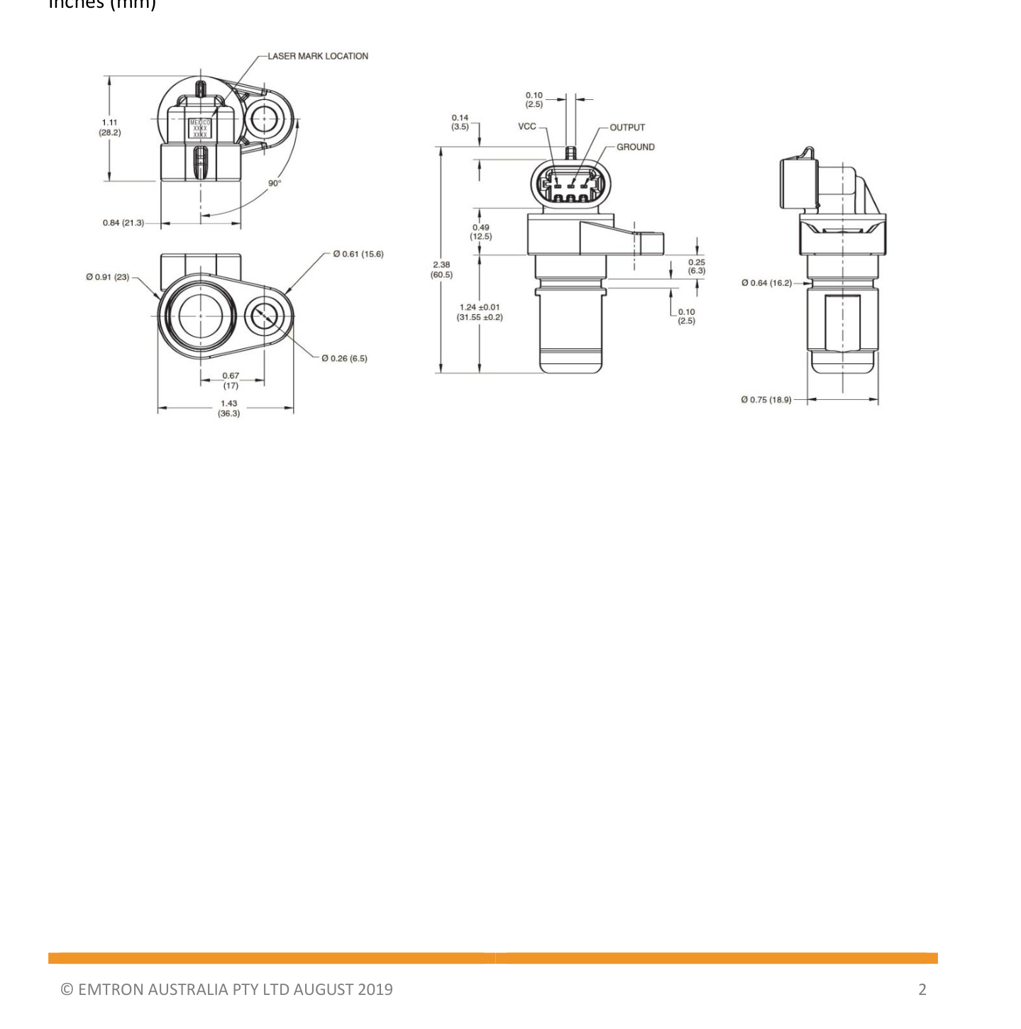
Gear Tooth Sensor dimensions and connector wiring — inches (mm).
2.2 Installation
For best results, targets should be produced from low carbon cold rolled steel. Other factors that influence sensor performance include gear tooth height and width, space between teeth, shape of the teeth and thickness of the target.
As a general guideline, consider a target within the following minimum parameters.
| Tooth Height (Min) | Tooth Width (Min) | Distance Between Teeth (Min) | Target Thickness (Min) |
|---|---|---|---|
| 0.200" (5.0mm) | 0.100" (2.5mm) | 0.400" (10mm) | 0.250" (6.35mm) |
2.3 Wiring
| Plug Pin | Sensor Pin | ECU Connection |
|---|---|---|
| A | VCC | CAS 8V or 5V VRef |
| B | OUTPUT | Available Crank / Sync / Digital Input |
| C | GROUND | GND (Do not connect to 0V Ref sensor ground) |
3.0 Ordering Information
| Product | Part Number |
|---|---|
| Gear Tooth Sensor (Sensor Only) | 52019-8 |
| Gear Tooth Sensor Kit (Includes Connector Kit) | 52019-811 |
| Gear Tooth Sensor Connector Kit | N/A |
10 Position Rotary Switch Datasheet
Description
The Emtron Rotary Switch is a high quality 10 position Rotary Switch that produces a stepped output voltage for each change in switch position. The output voltage will swing between ground and the supply. The switch is terminated with the reliable and environmentally sealed Deutsch DTM connector.
Features
- High quality single deck Grayhill rotary switch.
- Suitable for medium to high shock environments.
- Rotor contact: Brass, silver over nickel plate.
- Common ring: Brass, gold over silver over nickel plate.
- Max Supply Voltage: 5.00V to 20.00 Volts DC. NoteNOTE The supply MUST be regulated to generate a stable and consistent output voltage.
- Current supply: 4.5mA at 5.0V; 7.3mA at 8.0V
- The output voltage has linear stepping as the switch position changes.
- 5V Supply: Approximately 0.450V per position change (see calibration data below)
- 8V Supply: Approximately 0.720V per position change (see calibration data below)
Calibration Data
| Output Voltage (V), 5.0V Supply | Rotary Position | Output Voltage (V), 8.0V Supply | Rotary Position | |
|---|---|---|---|---|
| < 0.225 | Fault | < 0.365 | Fault | |
| 0.451 | 1 | 0.727 | 1 | |
| 0.901 | 2 | 1.448 | 2 | |
| 1.350 | 3 | 2.175 | 3 | |
| 1.815 | 4 | 2.924 | 4 | |
| 2.238 | 5 | 3.610 | 5 | |
| 2.702 | 6 | 4.350 | 6 | |
| 3.142 | 7 | 5.055 | 7 | |
| 3.597 | 8 | 5.763 | 8 | |
| 4.039 | 9 | 6.428 | 9 | |
| 4.481 | 10 | 7.100 | 10 | |
| > 4.770 | Fault | > 7.65 | Fault |
Wiring
Deutsch 3-Way Connector Pinout
| Pin | Function |
|---|---|
| 1 | 0V |
| 2 | Signal |
| 3 | 5V Supply |
Connect the Sensor 0V (Pin 1) to the ECU Sensor 0V Reference pin. DO NOT connect the 0V pin directly to the ECU ground or engine block.
Ordering Information
| Product | Part Number |
|---|---|
| Emtron 10 Position Switch DTM (Actuator Type - Small) | 1816-10S |
| Emtron 10 Position Switch DTM (Actuator Type - Large) | 1816-10L |
Ethanol Content Sensor (Continental)
The Emtron Ethanol Content (Flex Fuel) Sensor is a Continental sensor that measures the ethanol content of the fuel passing through it and outputs a frequency-based signal the ECU uses for flex-fuel compensation.
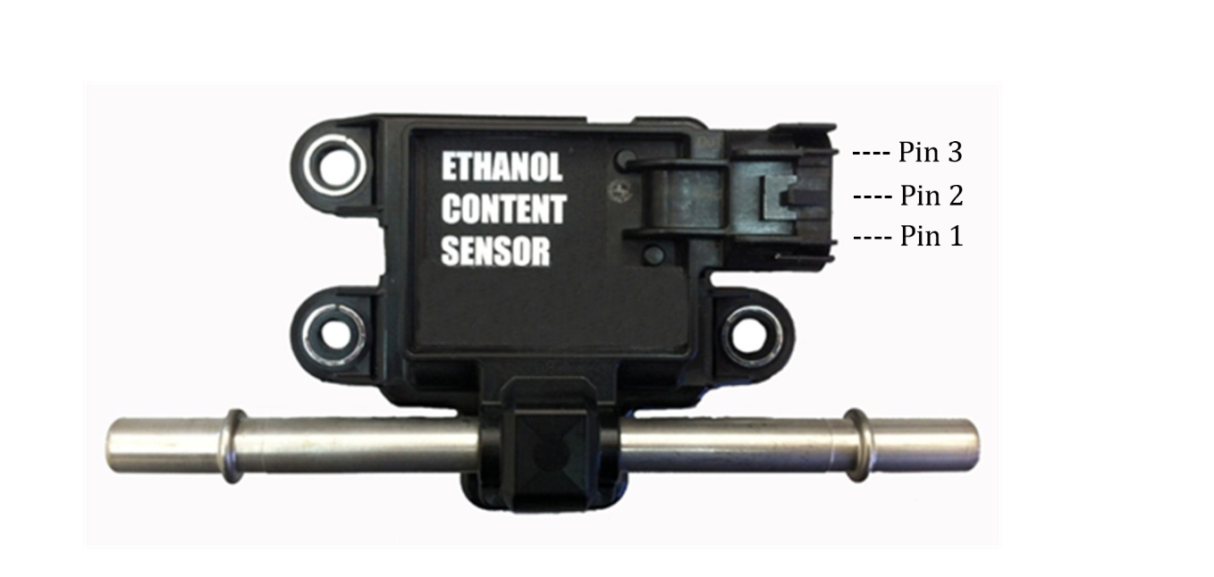
Continental Ethanol Content Sensor showing the three connector pins.
Wiring
| Pin | Function |
|---|---|
| 1 | 12V or ECU 8V Out |
| 2 | Ground |
| 3 | Output |
NoteNOTE The Output pin can be connected to any Digital Input Channel 1-8.