Subsections of Datasheets
TM16 Datasheet
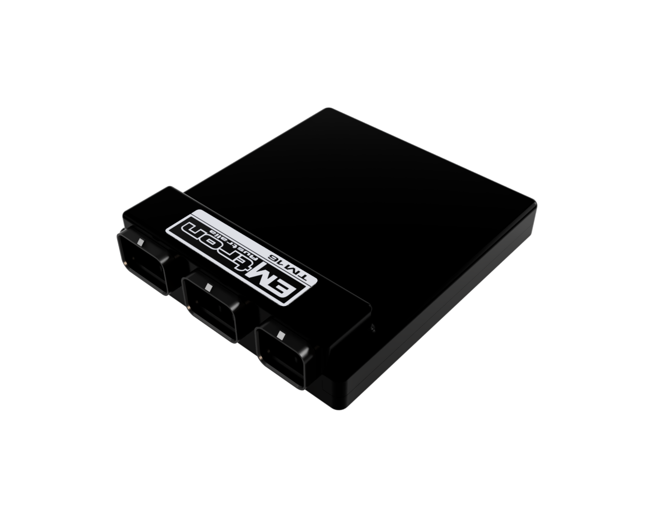
The Emtron TM16 is a fully programmable Transmission Control Module aimed at controlling the most complex transmission and driveline components. Designed with an over abundant amount of processing power to allow for the implementation of extremely complex, no compromise control strategies.
Overview
- 2x 650 MHz 32bit Automotive Processors
- Xilinx 7 Series FPGA
- 512 MB DDR3 RAM
- 8 GB Data Logging Memory
- Fully protected power supply inputs
- 16x Low Side Proportional Current Solenoid Outputs
- 8x Half-Bridge Auxiliary Outputs
- 4x Protected Solenoid Power Supply Outputs
- 4x Analogue Outputs
- 16x Analogue Inputs
- 16x Digital Inputs
- 4x 2 Wire Hall Effect Wheel Speed Inputs
- IMU (3 Axis Accelerometer & Gyroscope)
- Onboard Barometric Pressure Sensor
- 2x CAN 2.0A/B Busses
- 1x RS232 Interface
- 2x 5V Sensor Supplies
- 1x 8V Sensor Supply
- Ethernet PC Tuning
Applications
- Dual Clutch Transmissions
- Multi-Clutch Automatic Transmissions
- Conventional Automatic Transmissions
Wiring Pinout
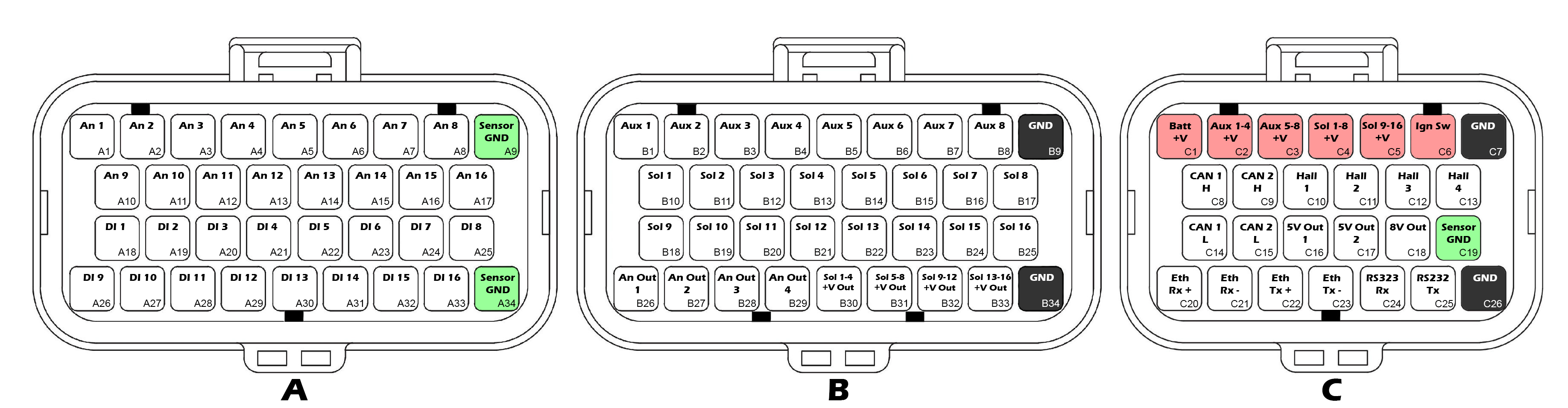
Looking into TCM
Connector A
InfoMating Connector: 4-1437290-0| Pin | Function |
|---|---|
| A1 | ANV 1 |
| A2 | ANV 2 |
| A3 | ANV 3 |
| A4 | ANV 4 |
| A5 | ANV 5 |
| A6 | ANV 6 |
| A7 | ANV 7 |
| A8 | ANV 8 |
| A9 | Sensor 0V Ref |
| A10 | ANV 9 |
| A11 | ANV 10 |
| A12 | ANV 11 |
| A13 | ANV 12 |
| A14 | ANV 13 |
| A15 | ANV 14 |
| A16 | ANV 15 |
| A17 | ANV 16 |
| A18 | DI 1 |
| A19 | DI 2 |
| A20 | DI 3 |
| A21 | DI 4 |
| A22 | DI 5 |
| A23 | DI 6 |
| A24 | DI 7 |
| A25 | DI 8 |
| A26 | DI 9 |
| A27 | DI 10 |
| A28 | DI 11 |
| A29 | DI 12 |
| A30 | DI 13 |
| A31 | DI 14 |
| A32 | DI 15 |
| A33 | DI 16 |
| A34 | Sensor 0V Ref |
Connector B
InfoMating Connector: 4-1437290-1| Pin | Function |
|---|---|
| B1 | Aux 1 |
| B2 | Aux 2 |
| B3 | Aux 3 |
| B4 | Aux 4 |
| B5 | Aux 5 |
| B6 | Aux 6 |
| B7 | Aux 7 |
| B8 | Aux 8 |
| B9 | GND |
| B10 | Solenoid 1 |
| B11 | Solenoid 2 |
| B12 | Solenoid 3 |
| B13 | Solenoid 4 |
| B14 | Solenoid 5 |
| B15 | Solenoid 6 |
| B16 | Solenoid 7 |
| B17 | Solenoid 8 |
| B18 | Solenoid 9 |
| B19 | Solenoid 10 |
| B20 | Solenoid 11 |
| B21 | Solenoid 12 |
| B22 | Solenoid 13 |
| B23 | Solenoid 14 |
| B24 | Solenoid 15 |
| B25 | Solenoid 16 |
| B26 | Analog Out 1 |
| B27 | Analog Out 2 |
| B28 | Analog Out 3 |
| B29 | Analog Out 4 |
| B30 | Solenoid 1-4 Supply Output |
| B31 | Solenoid 5-8 Supply Output |
| B32 | Solenoid 9-12 Supply Output |
| B33 | Solenoid 13-16 Supply Output |
| B34 | GND |
Connector C
InfoMating Connector: 3-1437290-7| Pin | Function |
|---|---|
| C1 | Battery Hot Supply |
| C2 | Aux 1-4 Supply |
| C3 | Aux 5-8 Supply |
| C4 | Solenoid 1-8 Supply |
| C5 | Solenoid 9-16 Supply |
| C6 | Ignition Switch |
| C7 | GND |
| C8 | CAN 1 Hi |
| C9 | CAN 2 Hi |
| C10 | Hall 1 |
| C11 | Hall 2 |
| C12 | Hall 3 |
| C13 | Hall 4 |
| C14 | CAN 1 Lo |
| C15 | CAN 2 Lo |
| C16 | 5V0 Ref Output 1 |
| C17 | 5V0 Ref Output 2 |
| C18 | 8V0 Ref Output |
| C19 | Sensor 0V Ref |
| C20 | Ethernet Rx+ |
| C21 | Ethernet Rx- |
| C22 | Ethernet Tx+ |
| C23 | Ethernet Tx- |
| C24 | RS232 Rx |
| C25 | RS232 Tx |
| C26 | GND |
Features
Power Supply
- Reverse polarity protection
- Over temperature protection
- Over current protection
- Current & voltage diagnostic monitoring
- 1x Battery constant supply
- 2x Auxiliary output driver supplies
- 2x Solenoid supplies
- 1x Ignition switch input
- 24V Compatible
Processor
- Dual Core, 650 MHz, 32bit Automotive Processor
- Xilinx 7 Series FPGA
- 512MB DDR3 RAM
Solenoid Outputs
16x Proportional Current Solenoid Drivers
- 0.1 – 20 KHz PWM
- Low side only
- 1.5A max current setpoint in single mode
- 2.7A max current setpoint in paired mode
- 1.8A continuous current per pin
- Current monitoring and control on all pins
- Current dither for reduced stiction and faster solenoid response
- Flywheel diodes connected to solenoid power supply outputs (see below)
- Unused solenoid outputs can be used as low side auxiliary outputs
Solenoid Power Supply Outputs x4
4x Protected Solenoid Supply Outputs
- Protected and monitored solenoid supply pins
- Over current protected
- Current & voltage diagnostic monitoring
Auxiliary Outputs
8x Auxiliary Outputs
- Half-Bridge Drivers
- 0.1 – 20 KHz PWM
- High Side / Low Side 35A peak, 8A continuous
- Bi-directional current monitoring on all pins
Analog Outputs
4x Analog Outputs
- 0-5V, 10 bit, 4.88 mV resolution
- 11 mA per channel
Analog Inputs
16x Analog Inputs
- 0-5V
- 12 bit, 1.22mV resolution
- Switchable 1K pullups to 5V Out 1 on pins 1-8
- Switchable 1K pullups to 5V Out 2 on pins 9-16
- 100K Ohms to ground
Digital Inputs
16x Digital Inputs
- 0.5 – 20KHz
- 0-39V Analog Input on all pins
- 12 bit, 9.52mV resolution
- Hall effect & Reluctor sensor compatible
- Switchable 4K7 pullup to 8.0V on all pins
- Switchable 330R pulldown to GND on pins 1-8
Digital Input 1-8:
- Programmable 0-5V high trigger threshold
- Programmable 0-5V low trigger threshold
Digital Input 9-16:
- Fixed high trigger threshold: 2.4V
- Fixed low trigger threshold: 0.5V
Hall Sensor Inputs
4x 2-Wire Hall Effect Sensor Inputs
- 0.5 – 20KHz
- Open circuit detection
- Short to Battery detection
- Short to Ground detection
Inertial Measurement Unit
- 3 Axis Accelerometer, ±2/4/8/16 g
- 3 Axis Gyroscope, ±125 - ±4000 dps
On board Sensors
- Barometric Pressure Sensor
- PCB Temperature Sensor
Communications
- 10/100 Ethernet PC tuning interface, high speed, high noise immunity
- 2x CAN 2.0A/B Interfaces, fully user configurable, selectable termination.
- 1x RS232 Serial Interface
Data Logging
- 8GB Onboard eMMC logging memory.
Programming
All device configuration and firmware updates are done via ethernet connection with our free TMtune PC Software.
TM16-R35 Adapter Datasheet
The TM16-R35 Adapter allows Plug-n-Play control of the Nissan GR6 DCT transmission in the 2007+ R35 GTR.
Pinout
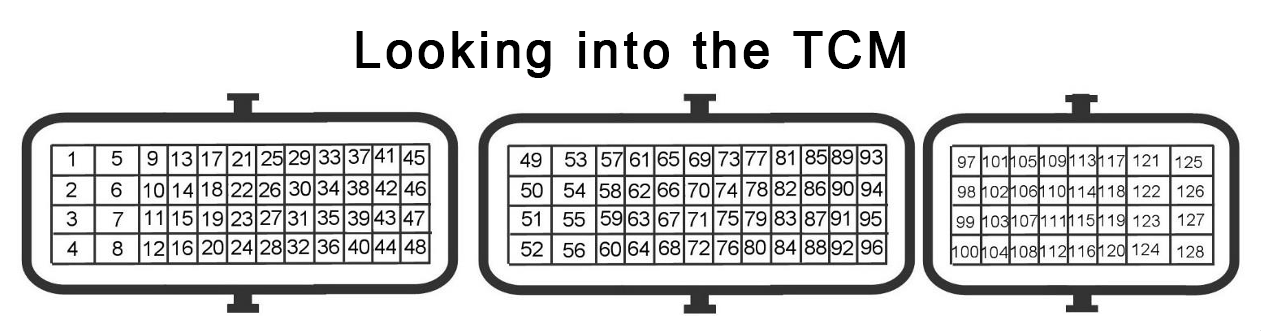
Connector A (Black)
| OEM Pin | Function | TM16 Pin |
|---|---|---|
| 1 | +14V (TCM Relay) | C2, C3, C4, C5 |
| 2 | - | |
| 3 | GND | B9, B34, C7, C26 |
| 4 | GND | B9, B34, C7, C26 |
| 5 | +14V (TCM Relay) | C2, C3, C4, C5 |
| 6 | - | |
| 7 | GND | B9, B34, C7, C26 |
| 8 | GND | B9, B34, C7, C26 |
| 9 | Batt +14V | C1 |
| 10 | Reverse Light Output | Sol 15 (B24) |
| 11 | CAN 1 H | C8 |
| 12 | - | |
| 13 | - | |
| 14 | TCM Power Relay | Sol 16 (B25) |
| 15 | CAN 1 L | C14 |
| 16 | Brake Switch 1 | DI 10 (A27) |
| 17 | Ignition Switch | C6 |
| 18 | - | |
| 19 | Starter Relay Enable | Aux 8 (B8) |
| 20 | - | |
| 21 | - | |
| 22 | - | |
| 23 | Manual Switch 1 | DI 7 (A24) |
| 24 | - | |
| 25 | 5V Ref 2 | C17 |
| 26 | 5V Ref 2 | C17 |
| 27 | Shifter Pos Switch 1 | ANV 9 (A10) |
| 28 | Manual Switch 2 | DI 8 (A25) |
| 29 | - | |
| 30 | - | |
| 31 | Engine Speed (Tracking) | DI 4 (A21) |
| 32 | - | |
| 33 | Shifter Pos Switch 2 | ANV 10 (A11) |
| 34 | Snow Mode Switch | DI 13 (A30) |
| 35 | Shifter Pos Switch 4 | ANV 12 (A13) |
| 36 | - | |
| 37 | R Mode Switch | DI 12 (A29) |
| 38 | Shifter Pos Switch 3 | ANV 11 (A12) |
| 39 | Up Shift Switch | DI 5 (A22) |
| 40 | - | |
| 41 | - | |
| 42 | Down Shift Switch | DI 6 (A23) |
| 43 | Shifter Pos Switch 5 | ANV 13 (A14) |
| 44 | Shifter Pos Switch 6 | ANV 14 (A15) |
| 45 | R Mode Lamp | Sol 13 (B22) |
| 46 | Shift Lock Solenoid | Aux 6 (B6) |
| 47 | Snow Mode Lamp | Sol 14 (B23) |
| 48 | - |
Connector B (Brown)
| OEM Pin | Function | TM16 Pin |
|---|---|---|
| 49 | Shift Solenoid 1 | Aux 1 (B1) |
| 50 | - | |
| 51 | Shift Solenoid 3 | Aux 3 (B3) |
| 52 | - | |
| 53 | Shift Solenoid 5 | Aux 5 (B5) |
| 54 | Shift Solenoid 2 | Aux 2 (B2) |
| 55 | - | |
| 56 | Shift Solenoid 4 | Aux 4 (B4) |
| 57 | Solenoid Supply | Sol 1-4 +V (B30) |
| 58 | - | |
| 59 | Solenoid Supply | Sol 5-8 +V (B31) |
| 60 | - | |
| 61 | - | |
| 62 | Axis A Solenoid | Sol 3 (B12) |
| 63 | - | |
| 64 | Axis B Solenoid | Sol 7 (B16) |
| 65 | - | |
| 66 | Sensor GND | A9, A34, C19 |
| 67 | Shift Fork 1 Pos (Main) | ANV 4 (A4) |
| 68 | Sensor GND | A9, A34, C19 |
| 69 | Sensor GND | A9, A34, C19 |
| 70 | Shift Fork 4 Pos (Main) | ANV 8 (A8) |
| 71 | 5V Ref 1 | C16 |
| 72 | Clutch A Speed | DI 1 (A18) |
| 73 | 5V Ref 1 | C16 |
| 74 | 5V Ref 1 | C16 |
| 75 | 5V Ref 1 | C16 |
| 76 | Speed Sensor + | (From TCM Relay) |
| 77 | Line Pressure Sensor | ANV 1 (A1) |
| 78 | Speed Sensor + | (From TCM Relay) |
| 79 | Shift Fork 1 Pos (Tracking) | ANV 5 (A5) |
| 80 | Sensor GND | A9, A34, C19 |
| 81 | 5V Ref 1 | C16 |
| 82 | Clutch B Speed | DI 2 (A19) |
| 83 | Sensor GND | A9, A34, C19 |
| 84 | Sensor GND | A9, A34, C19 |
| 85 | Shift Fork 2 Pos (Main) | ANV 6 (A6) |
| 86 | Sensor GND | A9, A34, C19 |
| 87 | Trans Fluid Temp | ANV 15 (A16) |
| 88 | 5V Ref 1 | C16 |
| 89 | Park Switch | DI 14 (A31) |
| 90 | - | |
| 91 | Sensor GND | A9, A34, C19 |
| 92 | Shift Fork 3 Pos (Main) | ANV 7 (A7) |
| 93 | - | |
| 94 | Sensor GND | A9, A34, C19 |
| 95 | - | |
| 96 | - |
Connector C (Grey)
| OEM Pin | Function | TM16 Pin |
|---|---|---|
| 97 | 5V Ref 1 | C16 |
| 98 | Clutch A Pressure | ANV 2 (A2) |
| 99 | Sensor GND | A9, A34, C19 |
| 100 | - | |
| 101 | - | |
| 102 | 5V Ref 1 | C16 |
| 103 | Clutch B Pressure | ANV 3 (A3) |
| 104 | Sensor GND | A9, A34, C19 |
| 105 | Speed Sensor + | (From TCM Relay) |
| 106 | Output Shaft Speed | DI 3 (A20) |
| 107 | Sensor GND | A9, A34, C19 |
| 108 | - | |
| 109 | - | |
| 110 | - | |
| 111 | - | |
| 112 | - | |
| 113 | Line Pressure Solenoid | Sol 9 (B18) |
| 114 | - | |
| 115 | Lubrication Flow Solenoid | Sol 11 (B20) |
| 116 | - | |
| 117 | - | |
| 118 | Solenoid Supply | Sol 9-12 +V (B32) |
| 119 | - | |
| 120 | Solenoid Supply | Sol 9-12 +V (B32) |
| 121 | Solenoid Supply | Sol 1-4 +V (B30) |
| 122 | - | |
| 123 | Solenoid Supply | Sol 5-8 +V (B31) |
| 124 | - | |
| 125 | - | |
| 126 | Clutch A Solenoid | Sol Pair 1&4 (B10+B13) |
| 127 | - | |
| 128 | Clutch B Solenoid | Sol Pair 5&8 (B14+B17) |
Changelog
Version 1.1 - 31/07/2026
Clutch solenoids now use Solenoid Pairs 1&4, 5&8 to allow more than 1.5A
The OEM solenoid current limit is 1.5A, which is also the setpoint limit of a single TM16 solenoid output. At 1.5A of current, the clutch will achieve approximately 17 Bar of clutch pressure. Solenoid outputs can be paired to achieve up to 2.7A (It’s unlikely that more than 2.0A is useful). Version 1.1 hardware supports the solenoid pairing.
The cal file should be updated to use the solenoid pairs in the output config.
Version 1.0 hardware can utilize the additional current by modifying the wiring to splice the TM16’s solenoid outputs 1&4 together, and 5&8 together.
Version 1.0 - 01/04/2026
Initial Release