Subsections of Transmission Control
TM16 FAQ
Supported Transmissions
The TCM has been designed to be as universally applicable as possible. In much the same way that an aftermarket engine management system doesn’t really know what engine it’s running, the TCM is never explicitly set to run a specific transmission. There’s no “Select your transmission” option anywhere. Instead, each applicable input, output and sub system is configured on a case by case basis to build a full configuration. Different transmissions will use different combinations of sub systems.
The TCM’s firmware is fully configurable in every aspect, with almost nothing hidden behind presets or obfuscated away from the tuner. This means that it is theoretically possible to control most modern transmissions, once you have physical control of the hardware (in some cases this will involve removing and bypassing mechatronics units).
Building a transmission config from scratch is a complex task that requires significant knowledge of all systems involved, but it is very much possible.
We are testing and building applications specific configurations in-house which will dramatically speed up the process of commissioning and tuning your transmission. Below is a list of the transmission that we’re focussing on. If you transmission isn’t in the list, that doesn’t mean it cannot be supported, it just means you might have to attempt it yourself.
Transmission Development Status
| Transmission | Type | Status | Base Cal | Notes |
|---|---|---|---|---|
| ZF 8HP | Multi-clutch | Supported | Included | |
| Nissan GR6 | DCT | Supported | Included | |
| Getrag GS7 | DCT | Supported | Included | |
| Porsche PDK | DCT | Planned | TBA | |
| VW DQ500 | DCT | Planned | TBA | |
| Tremec TR-9080 | DCT | Planned | TBA | |
| Audi DL800 | DCT | Planned | TBA | |
| GM 6L80E | Multi-clutch | Planned | TBA | |
| Ford 6R80 | Multi-clutch | Planned | TBA | |
| Ford 10R80 | Multi-clutch | Planned | TBA |
Supported ECU Platforms
The TM16 integrates seamlessly via CAN with all Emtron ECU’s, allowing for fully torque modelled shifting and down shift rev-matching with minimal setup complexity. This is by far the best way to achieve an OEM quality driving experience.
Additionally, the TCM also has a two fully open and configurable CAN bus nodes, meaning that users can send and receive any data required in any format to integrate almost any third party ECU. The level of control available is ultimately up to the ECU in question and will vary from extremely crude to fully featured depending on the ECU in question.
Critical signals such as Engine Speed and Pedal Position can also be inputted via physically wired inputs.
Integrating a third party ECU requires a solid understanding of all the systems in use, as well as a solid understanding of CAN bus communications.
The engine ECU must be capable of modelling and reporting accurate engine torque as well as abiding by torque reduction requests and meeting down shift rev match targets.
Usage outside of the Emtron ecosystem is provided as is. It is up to the end user to determine if a platform can be used and how to do so. Emtron cannot provide technical support for third party systems.
CAN Integrations
As well as a fully user definable CAN bus, the TCM does have some preset CAN data sets which are always being added to over time.
Available CAN Presets
| Preset | Direction | Note |
|---|---|---|
| Emtron Transmission Control | Rx & Tx | Emtron torque modelled CAN integration |
| Nissan R35 GTR TCM | Rx & Tx | Build Package |
| BMW F-Series Shifter | Rx & Tx |
Shifter Inputs
The TCM can use a wide variety of shifters including CAN bus, analog, digital switch arrays, individual switches, CAN keypads, or combinations of any of the aforementioned input types.
For more information on Shifter Inputs and Drive Modes, refer here.
Drive Modes and Map Switching
Shift tables can be switched using inputs from CAN bus, rotary switches, fixed switches, sensor input and user logic.
Table axes can be set to any one of over 1500 channels allowing a virtually limitless amount of flexibility.
Output Current Control vs Duty Cycle
The majority of transmission related output functions generate a target current setpoint in amps, rather than a fixed PWM duty cycle.
When a solenoid is commanded to draw a certain current, it’s physical position is extremely consistent, resulting in a stable and repeatable position regardless of system voltage and temperature variables. If a fixed duty cycle were used, the transmission may work well one moment, and poorly the next.
Every TCM output pin can be used in current control mode, including auxiliary outputs.
User Functions can be configured to output either a traditional PWM waveform, or a current setpoint.
Solenoid Dither Current
A small dither current waveform is superimposed over the current setpoint. This keeps the solenoid in a permanent state of micro-motion, helping overcome stiction and increasing solenoid value response.
Dither is available on Solenoid Outputs 1-16. Available on firmware v0.31 and above.
Unused Solenoid Output Pins
Unused solenoid output pins can be used as auxiliary outputs for any purpose, including User Functions.
Solenoid pins have a maximum PWM frequency of 20 KHz.
Unused Input Pins
Unused analog and digital input pins can be used as general purpose inputs.
Analog input pin voltages are measured at all times.
Digital input pin voltage, frequency, duty cycle, pulse width, period, and level are measured at all times.
Pin channels are free to be transmitted via CAN, effectively turning the TCM input an input expander.
Getting Started
Wiring
Read and follow the wiring information here. It’s very important that the TCM is powered correctly.
Mandatory Engine & Driver Inputs
The following inputs MUST be configured for normal transmission operation. Input’s can be sourced from physical inputs or CAN data.
When used with an Emtron ECU, simply enable the Emtron Transmission Control Rx/Tx data streams.
For more info on Emtron ECU Integration, see here.
Engine Speed
Engine RPM from the engine ECU is required.
Engine Torque
Torque data is used extensively by numerous sub systems and must be accurate. The ability of the TCM to control clutch pressures during a shift begins and ends with accurate input torque data.
Both of the following torque inputs are required:
Engine Torque (Available): The amount of engine torque available if no reductions were in place.
Engine Torque (Supplied): The amount of torque that is actually being supplied, inclusive of active reductions such as ignition retards and fuel or ignition cuts.
Torque should be positive when the engine is accelerating and negative when the engine is decelerating (or being driven by the driveline).
Pedal & Throttle Position
Pedal position represents the drivers intention and is more useful in most cases than throttle position, which is often manipulated by engine control sub systems.
In the case of a cable throttle (NOT RECOMMENDED), the Pedal Position input function will be OFF. Sub systems that require Pedal Position will fall back to looking for Throttle Position automatically. This excludes any table axes using Pedal Position, which will be required to be changed manually.
Pedal Position: Driver pedal position demand.
Throttle Position: Engine throttle position or throttle area demand.
Brake Switch
A switch that shows ON when the brake is applied. This is used by systems such as Takeup and DCT Gear Pre-selection.
Shift Control Inputs
A combination of inputs that allow the selection of drive modes and gears, such as:
- Shifter Position
- Up/Down shift switches
- Drive mode request buttons or switches
For more info on drive modes see here.
Additional Engine Inputs
The following inputs are recommended to improve the quality of transmission management:
- Engine Idle Target Speed
- Engine Idle Status (On/Off)
- Overrun Fuel Cut Status (On/Off)
- Engine Temperature
Mandatory Transmission Inputs
These inputs vary based on the transmission in question but most transmissions will require:
- Input Shaft Speed
- Output Shaft Speed
- Transmission Fluid Temperature
Dual Clutch Transmissions will also require:
- Clutch Speeds
- Shift Fork Positions
TCM to ECU Output Signals
At the bare minimum, the engine ECU needs to know when to reduce torque (cut) and when to rev-match (blip). Ideally the engine ECU should be listening to torque limit data so that during a shift (or any other time) the TCM is in control of the amount of torque supplied by the engine.
There are many runtime channels generated by the TCM that can be transmitted via CAN or output physically by User Functions driving output pins.
Useful runtime channels include:
- Gear: The currently engaged gear.
- Next Gear: Shows the gear that will be shifted into. When not shifting
Next Gearwill show the same asGear. - Previous Gear: Shows the gear that is being shifted out of. When not shifting
Previous Gearwill show the same asGear. - Up Shift Request: Normally Off (0). Transitions to On (1) for the entire duration of an up shift.
- Down Shift Request: Normally Off (0). Transitions to On (1) for the entire duration of a down shift.
- Up Shift Torque Limit Status: Normally Off (0). Transitions to On (1) while an up shift torque limit is in place.
- Up Shift Torque Limit: When no limit is in place, this channel will hold the Torque Limit Off value as configured (Eg: 6000nm). During an up shift torque limit, it will show the final torque limit value as requested by the TCM.
- Down Shift Rev Match Status: Normally Off (0). Transitions to On (1) while a down shift rev match is being requested.
- Rev Match Target: Normally 0 RPM. During a rev-match request the desired target RPM is shown.
- Rev Match Torque: Normally 0 NM. During a down shift rev-match request the TCM will calculate the unloaded engine torque required to lift the engine speed to the rev-match target.
Ethernet Connection
Once powered up, connect the TCM’s ethernet to your PC’s ethernet port (or USB ethernet adapter). There’s no need to set a static IP address. If you’re ethernet adapter is already setup for an Emtron ECU’s static IP, it can stay unchanged.
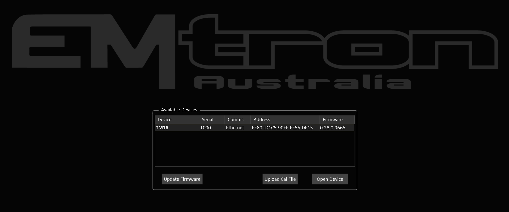
The initial connection will take about 5-10 seconds to establish. When the TCM is detected, TMtune will show the available devices panel.
Firmware
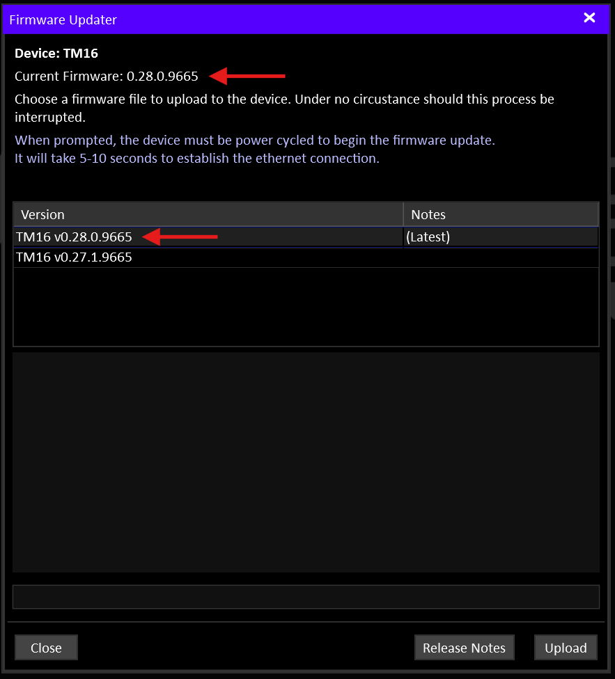
The latest TCM firmware is included with TMtune. Once detected you can select the TCM and click the Update Firmware button.
The firmware update window shows the current device firmware and lists the version available to upload (usually there will only be one). Unless the current firmware version is older than the latest version, there’s no need to update.
The update takes about 30 seconds to complete.
Transmission Specific Information
Read any documentation for your transmission if available. This list will grow over time as we develop more application specific base calibrations.
Base Cal File
If you are using a transmission with a base cal file available, now is the time to upload the latest base cal file. The files are included with TMtune. You can either upload the file from the welcome screen or you can open the device and upload a file from the File menu.
By default, base cal files are located in
Documents\Emtron\TMtune\Cal Files
Gear Ratios
Even if you’re using a base provided base calibration, it’s worth double checking the gear ratios are correct as many ratio options may exist for a given transmission.

The correct gear ratios must also be entered into the ECU.
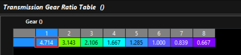
The TCM generates two gear ratio runtimes:
- Gear Ratio: the output from the gear ratio table
- Input/Output Shaft Speed Ratio: Input shaft speed / Output Shaft Speed.
These two values should be the same when in a driving gear. This is particularly useful for validating the input and output shaft speed sensors and that you are in the gear you think you are.
CAN
Ensure communications with the engine ECU are working. Follow the Emtron ECU Integration Guide to set up the ECU.
CAN Termination
Remember to set the CAN bus termination resistor(s) on or off as required for your bus topology.
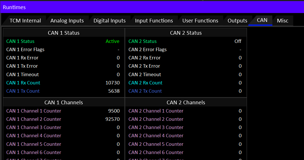
To quickly validate the state of the CAN bus, Goto the CAN tab in the F3 Runtimes window and ensure there are no errors and that the active channel counters are showing activity.
Validating I/O
Open the device and inspect a few key the live data channels.
Press F3 to open the Runtimes window:
- On the TCM Internal tab, ensure that ALL the power supply inputs are at battery voltage. Any that aren’t must be rectified or the TCM outputs will not work.
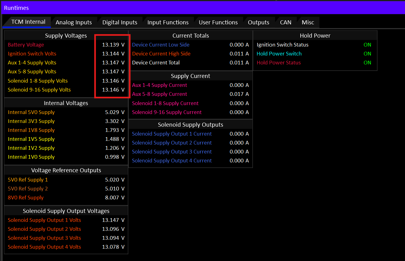
- Use the Analog Inputs and Digital Inputs tabs to validate the state of the raw inputs. Test that the raw inputs of switches and sensors are working as expected.
Testing Solenoids
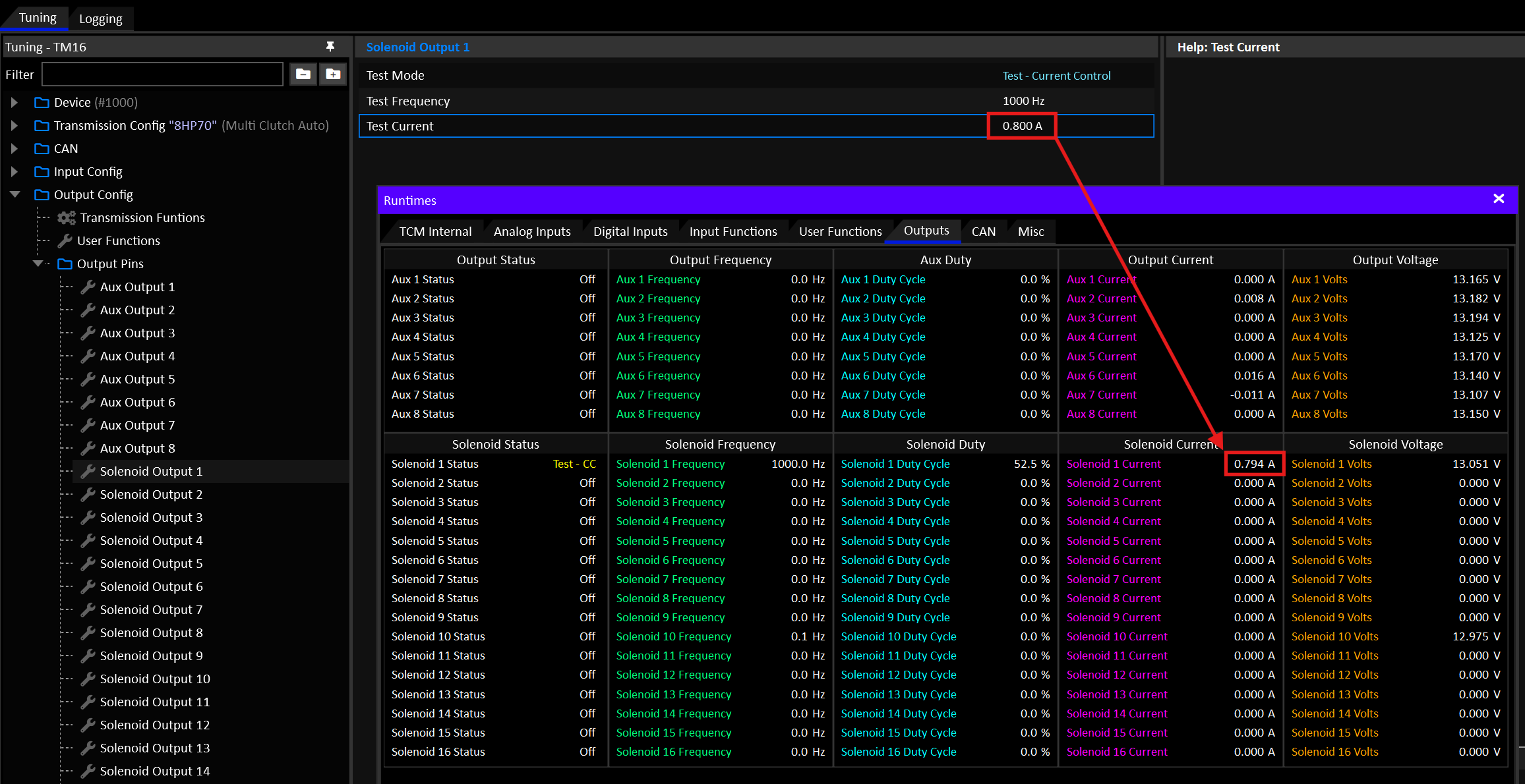
From the Config tree, navigate to Output Config > Output Pins. From there you can place each output into a test mode to validate it’s physical connection.
By putting the output into Test - Current Control mode you can command the solenoid to a desired current and check the result with the F3 Runtimes window on the Outputs tab.
The actual current draw of the solenoid should very closely match the target, as long as the solenoid isn’t saturated.
- A solenoid that saturates at 0.5A will never draw more than that.
- Most variable force transmission solenoids will be able to draw 1.0-1.5A.
- Smaller on/off type solenoids will typically be well under 1.0A.
- Just because a solenoid can draw a certain amount of current, does not mean it’s actually opening any further at maximum current. Solenoids will often hit their maximum position/stroke before current saturation.
Tip
If a solenoid doesn’t draw any current while being commanded to do so in test mode, it’s probably an open circuit.
High Current Solenoids (>1.5A)
A single solenoid output pin can command up to 1.5A. Some larger solenoids such as the clutch solenoids often found in DCT transmissions have a usable current in excess of 1.5A.
Solenoid outputs must be paired to supply solenoids with up to 2.7A.
Input Sources
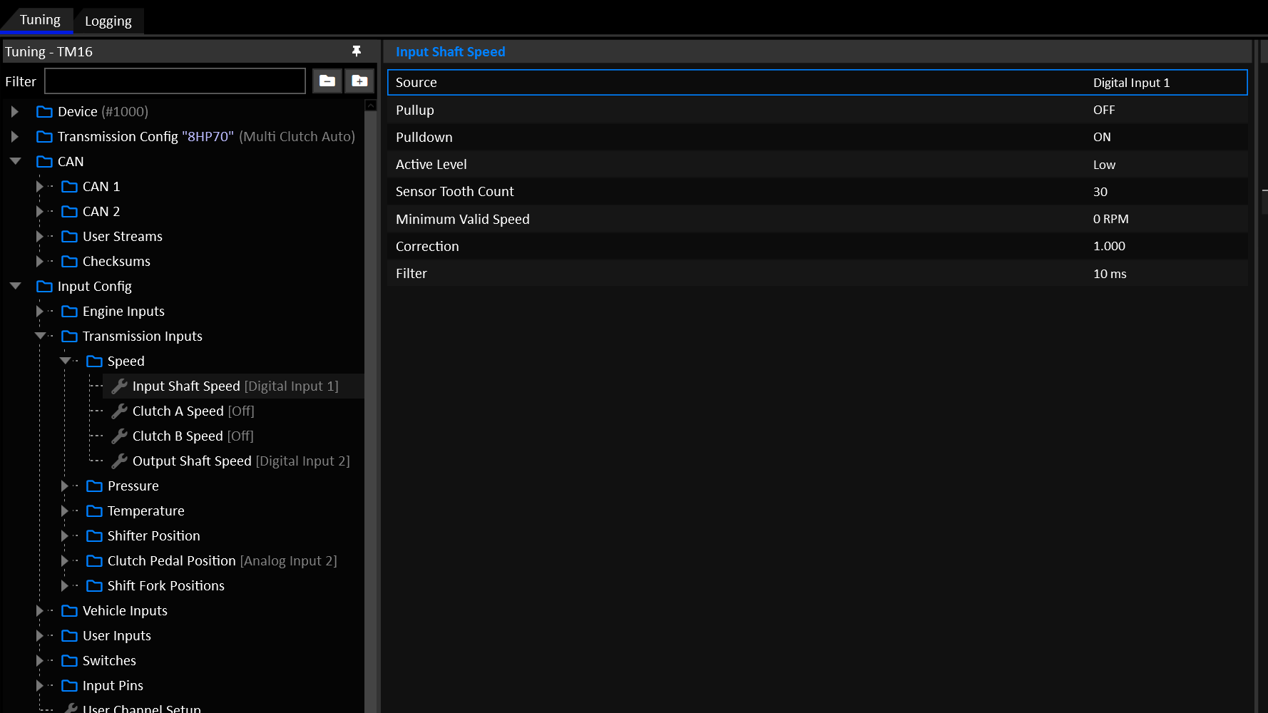
Under Input Config, ensure all relevant inputs are assigned to the correct source that matches the wiring and/or CAN configuration. This is particularly important if you’ve wired something different how the base cal file you’re using.
Output Assignment
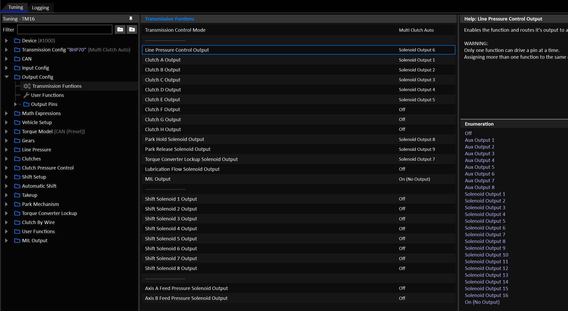
Under Output Config, ensure all relevant outputs are assigned to match your wiring.
Torque
Ensure that the received engine torque data is valid and realistic. Use the following criteria to validate the torque input…
With the engine unloaded in Neutral:
- Engine speed stable: Torque should be zero.
- Engine accelerating: Torque should be positive.
- Engine decelerating: Torque should be negative.
Torque figures should be verified against dyno figures. Remember that the torque given to the TCM will be flywheel torque, where-as on a chassis dyno, the figures will be wheel torque after drivetrain losses. For this reason it’s expected that the TCM’s input torque should always be higher than the dyno figures by some realistic margin to account for drivetrain losses.
Engine Inertia
A sensible value for engine inertia ensures that shifts synchronize well, with less reliance on closed loop control.
Under Vehicle Setup > Vehicle Setup enter an inertia value for the engine. You can also use the Engine Inertia Test mode to help find a useable value.
Important
Engine Inertia Test relies on accurate engine torque data to work.
Torque Limits
The most critical torque limit is the Up Shift Torque Limit. Now is a good time to make sure it has sensible values in it.
Navigate to Shift Setup > Up Shift > Up Shift Torque Limit.
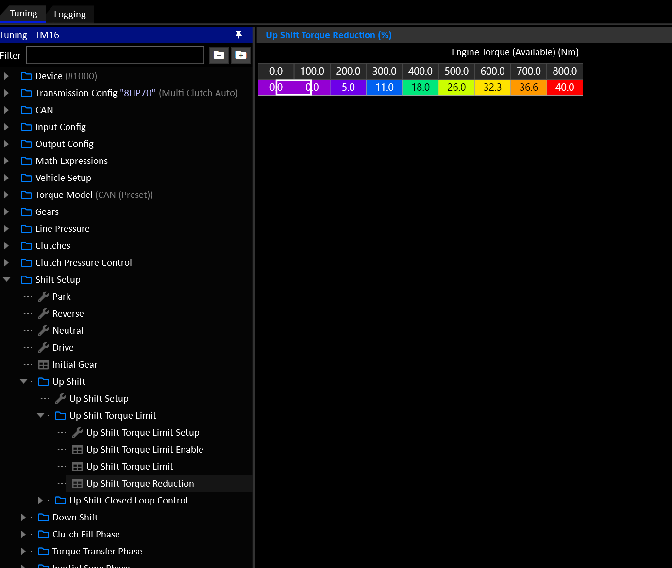
For more info of how torque reductions are applied, see here.
ECU Torque Control
Emtron ECU’s will abide by torque limits set by the TCM with very little tuning burden on the end user.
Frictional Loss
Torque is calculated by the ECU based on air mass. As long as the fuel system model is accurate the torque model will usually be very accurate. The user needs to focus primarily on validatingFrictional Loss.
When a torque reduction is requested, the ECU will use a combination of ignition retard and cut to achieve it.
Ignition Retard Scaling
The amount of retard used is calculated using the Torque Limit Ignition Retard Scaling Table. This table allows the ECU to lookup the amount of retard rquired for a given percentage of torque reduction, as well as how much torque will be reduced from a given retard value. Example:
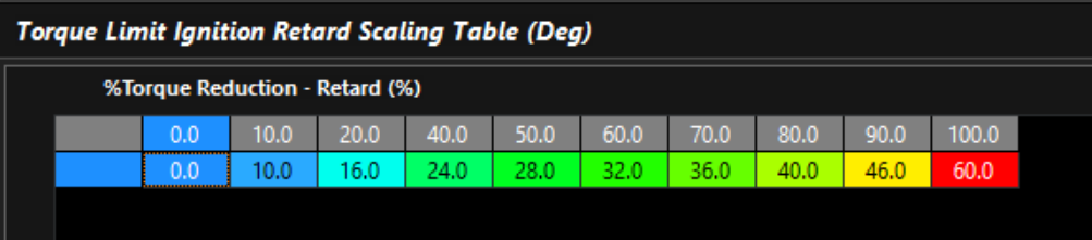
The Torque Limit Ignition Retard Scaling Table can be validated on the dyno by testing the torque reduction for a given global ignition trim. We have found that the above table is very useable for a wide range of applications without manual validation.
Cut Scaling
Similar to the ignition retard scaling, the amount of cut required for a given torque reduction is controlled by the Torque Limit Cut Gain Table. A value of 1.00 in this table tells the ECU that for a 50% torque reduction, it needs a 50% cut.

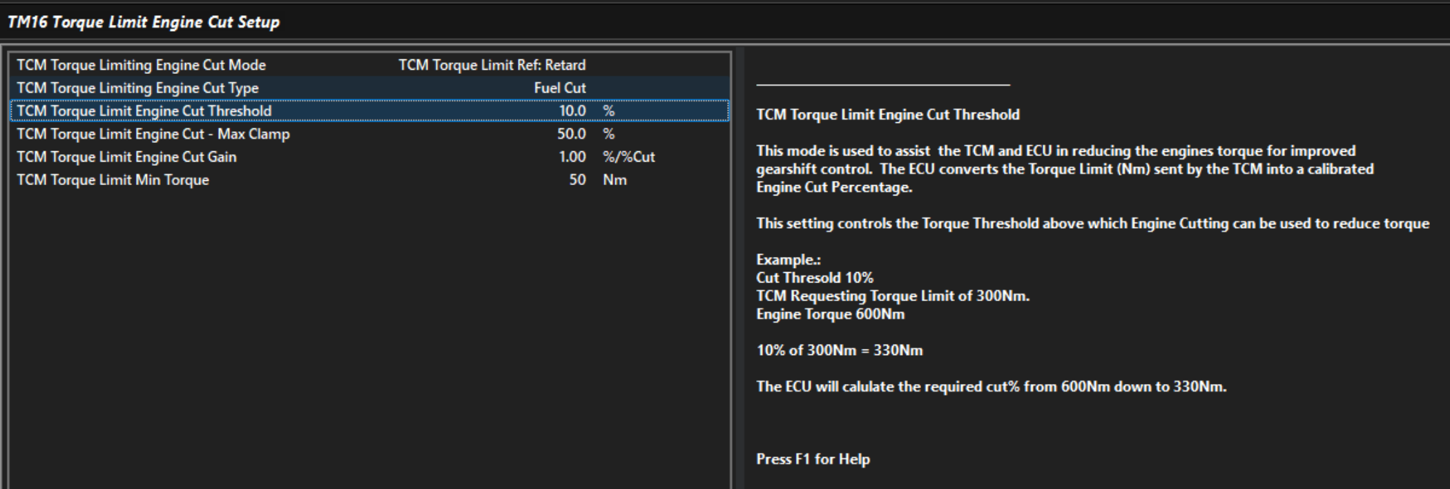
TM16 Engine Cut Setup
The TM16 will transmit a Fast and Slow torque limit value to the ECU. The Fast limit is used during shifts, the Slow limit is used during sustained torque limit such as the Global Torque Limit. The ECU interprets the Fast Limit as a retard based limit, and the Slow limit as a throttle based limit. In the TM16 Menu, you can control how the ECU converts the retard based fast limit into a cut with the TCM Torque Limit Engine Cut threshold. The lower this value is, the more cutting will be used to meet the torque limit.
Touch Points
Important
On every new install, you must find the clutch touch points.
The procedure for doing so is here.
Tuning
It’s common for tuners to be managing tuning the engine at the same time as the transmission. Once all the critical systems have been validated and all gears are confirmed working, you should be able to focus on the engine to get the ECU’s torque model validated.
Once you have confidence in the torque figures in the TCM, you can validate that the transmission operates correctly under load. How this looks will vary a lot depending on the transmission config.
Familiarize yourself with Multi-Clutch Shift Phases.
At this stage you should be able to:
- Engage all forward and reverse gears.
- Apply high torque in gear without any clutch slip.
- Change gear without excessive flaring or harshness.
Trouble Shooting
Clutch slip in gear
- Check the torque input is not too low.
- Line pressure is not too low.
- Clutch and line pressure solenoids are tracking their current targets.
Flaring on shifts
- Check the torque input is not too low.
- Check the Clutch Modelling
- Check the Clutch Touch Points
- If applicable, make sure a valid Clutch Gear Load Factor Table is in use.
- Line pressure is high enough to support the clutch pressure.
- Clutch and line pressure solenoids are tracking their current targets.
- Torque reductions are being acted on by the Engine ECU.
Wiring
Subsections of Wiring
Ethernet Wiring
The TCM uses 10/100Base-T Ethernet communications. It only requires 4 wires (2 pairs) to operate.
| Signal | MTC Pin | RJ45 Pin | Colour |
|---|---|---|---|
| Rx+ | C20 | 3 | Orange/White |
| Rx- | C21 | 6 | Orange |
| Tx+ | C22 | 1 | Green/White |
| Tx- | C23 | 2 | Green |
No special ethernet configuration is required. TMtune will detect the device using an IPv6 Link Local Address.
Hall Effect Inputs
Dedicated 2-Wire Hall Effect Inputs
The TCM contains 4 dedicated 2-wire hall effect inputs. These inputs are suitable for speed sensors found in many transmissions and ABS systems.
Unlike normal digital inputs, they actually provide the sensor with a regulated current source at the system’s battery voltage. When the sensing target passes the sensor, the current draw from the sensor will change. This change in current is used to determine an “edge”.
| Input | TCM Pin |
|---|---|
| Hall Input 1 | C10 |
| Hall Input 2 | C11 |
| Hall Input 3 | C12 |
| Hall Input 4 | C13 |
Info
The power supply for the hall inputs is sourced from Aux 1-4 Supply (Pin C2).
Each Hall Input outputs the following data:
- Frequency (0.5 – 20 KHz)
- Duty Cylce (%)
- Period (ms)
- Pulse Width (ms)
Known Applications
- BMW / Getrag GS7 DCT Input Shaft Speed & Clutch Speeds
- Toyota GT86 ABS Sensors
Wiring
| Sensor Pin | TCM Pin |
|---|---|
| Sensor Pin 1 | Hall Input 1-4 |
| Sensor Pin 2 | GND |
Note: The sensor may be grounded remotely.
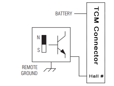
There’s no requirement to set arming thresholds or pulldown resistors.
Hall Inputs on DI 1-8
It’s possible to use 2-wire hall effect sensors on DI-18, and in some cases this is required.
The principle is similar but the wiring is very different. The sensor needs to be supplied with a regulated voltage (eg: 8.0V) and the signal wire goes to a digital input where it’s grounded through the internal pulldown resistor. This creates a measurable voltage that the TCM can use to measure rising and falling edges.
Known Applications
- ZF 8HP Input Shaft Speed & Output Shaft Speed
Wiring
| Sensor Pin | TCM Pin |
|---|---|
| Sensor Pin 1 | 8.0V |
| Sensor Pin 2 | DI 1-8 (Pulldown ON) |
Important
The input pin’s pulldown resistor must be enabled and the arming thresholds set correctly.
Arming Thresholds
The high and low arming thresholds must be set correctly to detect the speed signal. You can watch the raw voltage of the digital input pin to determine the thresholds.
- The low threshold must be ABOVE the sensor voltage at rest.
- The high threshold must be BELOW the maximum voltage when the sensor is active.
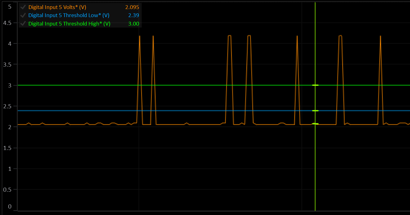
: If the voltage is near 0V or near the 8V supply, the sensor is probably wired wrong.
Power Supply
This document outlines the correct wiring of the TCM’s power supplies and power outputs.
Power Supplies
The TCM can be used in 12V or 24V systems with a nominal supply voltage of 9-32V.
All power supply pins are protected against reverse polarity, over current, over voltage, over temperature, transients and load dumps.
Voltages are clamped internally to 35V.
Important
All power supply pins must be wired, even if you’re not using them. Eg: Don’t skip the Auxiliary Supply inputs because you don’t need to use the auxiliary outputs.
Battery Hot Supply
| Pin | Voltage | Current |
|---|---|---|
| C1 | 9-32V | < 1A |
Warning
This pin must be powered at all times to allow the TCM to control it’s own power supply. Failure to do so may result in data logging memory being corrupted.
When more than ~3.5V is present on the Ignition Switch pin (C6), the internal circuitry will turn on the circuits connected to pin C1 and the TCM will power up.
Once the TCM is booted, the CPU will latch the internal power switch ON. In this state, if the voltage on the Ignition Switch pin drops to 0, the TCM will remain on until the CPU completes any pending critical tasks and disables the internal power latch.
When the TCM is off, this pin does NOT draw any current.
Ignition Switch
| Pin | Voltage | Current |
|---|---|---|
| C6 | 9-32V | < 3mA |
Info
The Ignition Switch pin does NOT supply any power to the device. Without connecting the Battery Hot Supply pin (C1), the TCM will not power up.
The ignitions switch serves only to enable the internal power switch connected to pin C1. It’s voltage is monitored by the TCM at all times and the data is available to the user.
Auxiliary Supplies
| Pin | Voltage | Current |
|---|---|---|
| C2 | 9-32V | 15A max, Application Specific |
| C3 | 9-32V | 15A max, Application Specific |
Pins C2 and C3 supply the half bridge drivers on Aux Output 1-8. The current draw of these inputs is determined by the total high side current of the Auxiliary outputs.
The auxiliary outputs are split into 2 banks of 4: 1-4 and 5-8. The total continuous high side current of a single bank should not exceed 15A for an extended period of time.
Auxiliary Supply pins can be supplied with constant or switched power, as long as they are always powered when the ignition switch is on. The TCM will only turn them on when the ignition switch is on.
Solenoid Supplies
| Pin | Voltage | Current |
|---|---|---|
| C4 | 9-32V | 15A max, Application Specific |
| C5 | 9-32V | 15A max, Application Specific |
Pins C4 and C5 supply the Solenoid power output pins (B30-B33) as well as the flywheel diodes and voltage monitors of the solenoid drivers.
Solenoid Supply pins can be supplied with constant or switched power, as long as they are always powered when the ignition switch is on. The TCM will only turn them on when the Ignition switch is on.
Solenoid Power Outputs
| Pin | Solenoids | Continuous Current |
|---|---|---|
| B30 | 1-4 | 7.5A |
| B31 | 5-8 | 7.5A |
| B32 | 9-12 | 7.5A |
| B33 | 13-16 | 7.5A |
The 4 Solenoid Power Supply Output pins are intended to supply the high side of the solenoids driven by any of the 16 Solenoid Output pins.
All supply outputs are protected against reverse polarity, short to ground, over current, over voltage, over temperature.
Ideally, you should supply the solenoids with their respective linked output. This means that in the event of a critical fault, the TCM can shut down the supply to the problem solenoid bank. Some applications will not be flexible enough to allow this. Best judgement should be used to make the system as robust as possible.
Example: ZF 8HP: There is only 1 solenoid supply pin for 9 solenoids. You can join two or more output pins to increase to total current capacity of the supply.
Note: During normal operation in a typical transmission, not all solenoids are on at the same time and not all solenoids will be commanding maximum current.
Reference
Subsections of Reference
Error Codes
Firmware Version
The following error codes are applicable to the latest firmware: v0.41.0
Other firmware versions may differ.
| # | Code | Description |
|---|---|---|
| 0 | OK | No Errors |
| 1 | Generic | |
| 2 | CPU Core 1 Fault | |
| 3 | CPU Core 2 Fault | |
| 4 | Operating System Stack Overflow | |
| 5 | Operating System Thread Create Failed | |
| 6 | Operating System Thread Delete Failed | |
| 7 | Operating System Queue Create Failed | |
| 8 | SPI 0 Fault | |
| 9 | ADC 1 Hardware Comms Fault | |
| 10 | ADC 2 Hardware Comms Fault | |
| 11 | ADC 3 Hardware Comms Fault | |
| 12 | SPI 1 Fault | |
| 13 | IMU Hardware Comms Fault | |
| 14 | Digital Arming Threshold Hardware Comms Fault | |
| 15 | Solenoid Bank 1 Hardware Comms Fault | |
| 16 | Solenoid Bank 2 Hardware Comms Fault | |
| 17 | Solenoid Bank 3 Hardware Comms Fault | |
| 18 | Solenoid Bank 4 Hardware Comms Fault | |
| 19 | Analog Output DAC Hardware Comms Fault | |
| 20 | CAN 1 Hardware Fault | |
| 21 | CAN 1 Timeout | |
| 22 | CAN 1 Rx Error | |
| 23 | CAN 1 Tx Error | |
| 24 | CAN 1 Bus Off | |
| 25 | CAN 1 Stuff Error | |
| 26 | CAN 2 Hardware Fault | |
| 27 | CAN 2 Timeout | |
| 28 | CAN 2 Rx Error | |
| 29 | CAN 2 Tx Error | |
| 30 | CAN 2 Bus Off | |
| 31 | CAN 2 Stuff Error | |
| 32 | Flash Read Error | |
| 33 | Flash Write Error | |
| 34 | Flash Erase Error | |
| 35 | EMMC Read Error | |
| 36 | EMMC Write Error | |
| 37 | EMMC Erase Error | |
| 38 | Ethernet Hardware Fault | |
| 39 | Ethernet Timeout | |
| 40 | Ethernet Rx Error | |
| 41 | Ethernet Tx Error | |
| 42 | Ethernet Link Down | |
| 43 | IMU Hardware Fault | |
| 44 | IMU Initialisation Error | |
| 45 | IMU Read Error | |
| 46 | IMU Write Error | |
| 47 | IMU Calibration Error | |
| 48 | IMU Data Error | |
| 49 | Barometer Input Low | |
| 50 | Barometer Input High | |
| 51 | PCB Temp Sensor Low | |
| 52 | PCB Temp Sensor High | |
| 53 | Output Pin Conflict | |
| 64 | Main Supply Voltage Low | |
| 65 | Main Supply Voltage High | |
| 66 | Aux Bank 1 Voltage Low | |
| 67 | Aux Bank 1 Voltage High | |
| 68 | Aux Bank 2 Voltage Low | |
| 69 | Aux Bank 2 Voltage High | |
| 70 | Solenoid Bank 1 Voltage Low | |
| 71 | Solenoid Bank 1 Voltage High | |
| 72 | Solenoid Bank 2 Voltage Low | |
| 73 | Solenoid Bank 2 Voltage High | |
| 74 | Solenoid Bank 3 Voltage Low | |
| 75 | Solenoid Bank 3 Voltage High | |
| 76 | Solenoid Bank 4 Voltage Low | |
| 77 | Solenoid Bank 4 Voltage High | |
| 78 | Main Supply Under Current | |
| 79 | Main Supply Over Current | |
| 80 | Aux Bank 1 Over Current | |
| 81 | Aux Bank 2 Over Current | |
| 82 | Solenoid Bank 1 Over Current | |
| 83 | Solenoid Bank 2 Over Current | |
| 84 | Solenoid Bank 3 Over Current | |
| 85 | Solenoid Bank 4 Over Current | |
| 86 | Solenoid Output Voltage 1 Low | |
| 87 | Solenoid Output Voltage 1 High | |
| 88 | Solenoid Output Voltage 2 Low | |
| 89 | Solenoid Output Voltage 2 High | |
| 90 | Solenoid Output Voltage 3 Low | |
| 91 | Solenoid Output Voltage 3 High | |
| 92 | Solenoid Output Voltage 4 Low | |
| 93 | Solenoid Output Voltage 4 High | |
| 96 | Internal 5V0 Supply Low | |
| 97 | Internal 5V0 Supply High | |
| 98 | Internal 3V3 Supply Low | |
| 99 | Internal 3V3 Supply High | |
| 100 | Internal 1V8 Supply Low | |
| 101 | Internal 1V8 Supply High | |
| 102 | Internal 1V2 Supply Low | |
| 103 | Internal 1V2 Supply High | |
| 104 | Internal 1V0 Supply Low | |
| 105 | Internal 1V0 Supply High | |
| 106 | Internal 1V5 Supply Low | |
| 107 | Internal 1V5 Supply High | |
| 108 | 5V0 Reference Supply 1 Low | |
| 109 | 5V0 Reference Supply 1 High | |
| 110 | 5V0 Reference Supply 2 Low | |
| 111 | 5V0 Reference Supply 2 High | |
| 112 | 8V0 Reference Supply Low | |
| 113 | 8V0 Reference Supply High | |
| 114 | Ignition Switch Low | |
| 115 | Ignition Switch High | |
| 116 | CPU Temperature Low | |
| 117 | CPU Temperature High | |
| 118 | IMU Temperature Low | |
| 119 | IMU Temperature High | |
| 120 | PCB Temperature Low | |
| 121 | PCB Temperature High | |
| 122 | Gear Ratio Table Invalid | |
| 123 | Gear Solenoid Table Invalid | |
| 124 | Gear Clutch Table Invalid | |
| 125 | Takeup Clutch Table Invalid | |
| 126 | Clutch By Wire Clutch Table Invalid | |
| 127 | Gear Axis Config Invalid | |
| 128 | Line Pressure Sensor Low | |
| 129 | Line Pressure Sensor High | |
| 130 | Line Pressure Solenoid | |
| 131 | Line Pressure Control | |
| 132 | Clutch A Pressure Sensor Low | |
| 133 | Clutch A Pressure Sensor High | |
| 134 | Clutch A Pressure Solenoid | |
| 135 | Clutch A Pressure Control | |
| 136 | Clutch B Pressure Sensor Low | |
| 137 | Clutch B Pressure Sensor High | |
| 138 | Clutch B Pressure Solenoid | |
| 139 | Clutch B Pressure Control | |
| 140 | Clutch C Pressure Sensor Low | |
| 141 | Clutch C Pressure Sensor High | |
| 142 | Clutch C Pressure Solenoid | |
| 143 | Clutch C Pressure Control | |
| 144 | Clutch D Pressure Sensor Low | |
| 145 | Clutch D Pressure Sensor High | |
| 146 | Clutch D Pressure Solenoid | |
| 147 | Clutch D Pressure Control | |
| 148 | Clutch E Pressure Sensor Low | |
| 149 | Clutch E Pressure Sensor High | |
| 150 | Clutch E Pressure Solenoid | |
| 151 | Clutch E Pressure Control | |
| 152 | Clutch F Pressure Sensor Low | |
| 153 | Clutch F Pressure Sensor High | |
| 154 | Clutch F Pressure Solenoid | |
| 155 | Clutch F Pressure Control | |
| 156 | Clutch G Pressure Sensor Low | |
| 157 | Clutch G Pressure Sensor High | |
| 158 | Clutch G Pressure Solenoid | |
| 159 | Clutch G Pressure Control | |
| 160 | Clutch H Pressure Sensor Low | |
| 161 | Clutch H Pressure Sensor High | |
| 162 | Clutch H Pressure Solenoid | |
| 163 | Clutch H Pressure Control | |
| 164 | Axis A Pressure Sensor Low | |
| 165 | Axis A Pressure Sensor High | |
| 166 | Axis A Pressure Solenoid | |
| 167 | Axis A Pressure Control | |
| 168 | Axis B Pressure Sensor Low | |
| 169 | Axis B Pressure Sensor High | |
| 170 | Axis B Pressure Solenoid | |
| 171 | Axis B Pressure Control | |
| 172 | Transmission Fluid Temp Sensor Low | |
| 173 | Transmission Fluid Temp Sensor High | |
| 174 | Clutch A Temp Sensor Low | |
| 175 | Clutch A Temp Sensor High | |
| 176 | Clutch B Temp Sensor Low | |
| 177 | Clutch B Temp Sensor High | |
| 178 | Clutch C Temp Sensor Low | |
| 179 | Clutch C Temp Sensor High | |
| 180 | Clutch D Temp Sensor Low | |
| 181 | Clutch D Temp Sensor High | |
| 182 | Clutch E Temp Sensor Low | |
| 183 | Clutch E Temp Sensor High | |
| 184 | Clutch F Temp Sensor Low | |
| 185 | Clutch F Temp Sensor High | |
| 186 | Clutch G Temp Sensor Low | |
| 187 | Clutch G Temp Sensor High | |
| 188 | Clutch H Temp Sensor Low | |
| 189 | Clutch H Temp Sensor High | |
| 190 | Oil Level Sensor Low | |
| 191 | Oil Level Sensor High | |
| 192 | Engine Speed Input Missing | |
| 193 | Engine Speed Signal Error | |
| 194 | Engine Speed Tracking Disagreement | |
| 195 | Input Shaft Speed Input Missing | |
| 196 | Input Shaft Speed Signal Error | |
| 197 | Output Shaft Speed Input Missing | |
| 198 | Output Shaft Speed Signal Error | |
| 199 | Throttle Position Sensor Low | |
| 200 | Throttle Position Sensor High | |
| 201 | Throttle Position Tracking Sensor Low | |
| 202 | Throttle Position Tracking Sensor High | |
| 203 | Throttle Position Tracking Disagreement | |
| 204 | Throttle 2 Position Sensor Low | |
| 205 | Throttle 2 Position Sensor High | |
| 206 | Throttle 2 Position Tracking Sensor Low | |
| 207 | Throttle 2 Position Tracking Sensor High | |
| 208 | Throttle 2 Position Tracking Disagreement | |
| 209 | Pedal Position Sensor Low | |
| 210 | Pedal Position Sensor High | |
| 211 | Pedal Position Tracking Sensor Low | |
| 212 | Pedal Position Tracking Sensor High | |
| 213 | Pedal Position Tracking Disagreement | |
| 214 | Axis A Pressure Sensor Low | |
| 215 | Axis A Pressure Sensor High | |
| 216 | Axis B Pressure Sensor Low | |
| 217 | Axis B Pressure Sensor High | |
| 218 | Brake Front Pressure Sensor Low | |
| 219 | Brake Front Pressure Sensor High | |
| 220 | Brake Rear Pressure Sensor Low | |
| 221 | Brake Rear Pressure Sensor High | |
| 222 | Clutch Pedal Position Sensor Low | |
| 223 | Clutch Pedal Position Sensor High | |
| 224 | Fork 1 Position Sensor Low | |
| 225 | Fork 1 Position Sensor High | |
| 226 | Fork 1 Tracking Sensor Low | |
| 227 | Fork 1 Tracking Sensor High | |
| 228 | Fork 2 Position Sensor Low | |
| 229 | Fork 2 Position Sensor High | |
| 230 | Fork 2 Tracking Sensor Low | |
| 231 | Fork 2 Tracking Sensor High | |
| 232 | Fork 3 Position Sensor Low | |
| 233 | Fork 3 Position Sensor High | |
| 234 | Fork 3 Tracking Sensor Low | |
| 235 | Fork 3 Tracking Sensor High | |
| 236 | Fork 4 Position Sensor Low | |
| 237 | Fork 4 Position Sensor High | |
| 238 | Fork 4 Tracking Sensor Low | |
| 239 | Fork 4 Tracking Sensor High | |
| 240 | Fork 5 Position Sensor Low | |
| 241 | Fork 5 Position Sensor High | |
| 242 | Fork 5 Tracking Sensor Low | |
| 243 | Fork 5 Tracking Sensor High | |
| 244 | Fork 6 Position Sensor Low | |
| 245 | Fork 6 Position Sensor High | |
| 246 | Fork 6 Tracking Sensor Low | |
| 247 | Fork 6 Tracking Sensor High | |
| 248 | Fork 7 Position Sensor Low | |
| 249 | Fork 7 Position Sensor High | |
| 250 | Fork 7 Tracking Sensor Low | |
| 251 | Fork 7 Tracking Sensor High | |
| 252 | Fork 8 Position Sensor Low | |
| 253 | Fork 8 Position Sensor High | |
| 254 | Fork 8 Tracking Sensor Low | |
| 255 | Fork 8 Tracking Sensor High | |
| 256 | Fork 1 Position Tracking Disagreement | |
| 257 | Fork 2 Position Tracking Disagreement | |
| 258 | Fork 3 Position Tracking Disagreement | |
| 259 | Fork 4 Position Tracking Disagreement | |
| 260 | Fork 5 Position Tracking Disagreement | |
| 261 | Fork 6 Position Tracking Disagreement | |
| 262 | Fork 7 Position Tracking Disagreement | |
| 263 | Fork 8 Position Tracking Disagreement | |
| 264 | Fork 1 Shift Solenoid Table Invalid | |
| 265 | Fork 2 Shift Solenoid Table Invalid | |
| 266 | Fork 3 Shift Solenoid Table Invalid | |
| 267 | Fork 4 Shift Solenoid Table Invalid | |
| 268 | Fork 5 Shift Solenoid Table Invalid | |
| 269 | Fork 6 Shift Solenoid Table Invalid | |
| 270 | Fork 7 Shift Solenoid Table Invalid | |
| 271 | Fork 8 Shift Solenoid Table Invalid | |
| 272 | Fork Default Solenoid Table Invalid | |
| 273 | Fork Idle Solenoid Table Invalid | |
| 274 | Trans Fluid Cooler Temp Sensor Low | |
| 275 | Trans Fluid Cooler Temp Sensor High | |
| 276 | Shifter Pos Sensor Low | |
| 277 | Shifter Pos Sensor High | |
| 288 | Clutch A Slip | |
| 289 | Clutch B Slip | |
| 290 | Clutch C Slip | |
| 291 | Clutch D Slip | |
| 292 | Clutch E Slip | |
| 293 | Clutch F Slip | |
| 294 | Clutch G Slip | |
| 295 | Clutch H Slip | |
| 296 | Axis A Fault | |
| 297 | Axis B Fault | |
| 298 | Axis A Bound | |
| 299 | Axis B Bound | |
| 300 | Fork 1 Movement | |
| 301 | Fork 2 Movement | |
| 302 | Fork 3 Movement | |
| 303 | Fork 4 Movement | |
| 304 | Fork 5 Movement | |
| 305 | Fork 6 Movement | |
| 306 | Fork 7 Movement | |
| 307 | Fork 8 Movement | |
| 308 | Gear Ratio Implausible | |
| 309 | Clutch Gear Load Factor Table Invalid | |
| 310 | User Input 1 Input Low | |
| 311 | User Input 1 Input High | |
| 312 | User Input 2 Input Low | |
| 313 | User Input 2 Input High | |
| 314 | User Input 3 Input Low | |
| 315 | User Input 3 Input High | |
| 316 | User Input 4 Input Low | |
| 317 | User Input 4 Input High | |
| 318 | User Input 5 Input Low | |
| 319 | User Input 5 Input High | |
| 320 | User Input 6 Input Low | |
| 321 | User Input 6 Input High | |
| 322 | User Input 7 Input Low | |
| 323 | User Input 7 Input High | |
| 324 | User Input 8 Input Low | |
| 325 | User Input 8 Input High | |
| 326 | User Input 9 Input Low | |
| 327 | User Input 9 Input High | |
| 328 | User Input 10 Input Low | |
| 329 | User Input 10 Input High | |
| 330 | User Input 11 Input Low | |
| 331 | User Input 11 Input High | |
| 332 | User Input 12 Input Low | |
| 333 | User Input 12 Input High | |
| 334 | User Input 13 Input Low | |
| 335 | User Input 13 Input High | |
| 336 | User Input 14 Input Low | |
| 337 | User Input 14 Input High | |
| 338 | User Input 15 Input Low | |
| 339 | User Input 15 Input High | |
| 340 | User Input 16 Input Low | |
| 341 | User Input 16 Input High | |
| 342 | Transbrake Clutch Select Table Invalid | |
| 352 | Solenoid 1 Open Load | |
| 353 | Solenoid 1 Over Current | |
| 354 | Solenoid 1 Short To Ground | |
| 355 | Solenoid 1 Over Temp | |
| 356 | Solenoid 2 Open Load | |
| 357 | Solenoid 2 Over Current | |
| 358 | Solenoid 2 Short To Ground | |
| 359 | Solenoid 2 Over Temp | |
| 360 | Solenoid 3 Open Load | |
| 361 | Solenoid 3 Over Current | |
| 362 | Solenoid 3 Short To Ground | |
| 363 | Solenoid 3 Over Temp | |
| 364 | Solenoid 4 Open Load | |
| 365 | Solenoid 4 Over Current | |
| 366 | Solenoid 4 Short To Ground | |
| 367 | Solenoid 4 Over Temp | |
| 368 | Solenoid 5 Open Load | |
| 369 | Solenoid 5 Over Current | |
| 370 | Solenoid 5 Short To Ground | |
| 371 | Solenoid 5 Over Temp | |
| 372 | Solenoid 6 Open Load | |
| 373 | Solenoid 6 Over Current | |
| 374 | Solenoid 6 Short To Ground | |
| 375 | Solenoid 6 Over Temp | |
| 376 | Solenoid 7 Open Load | |
| 377 | Solenoid 7 Over Current | |
| 378 | Solenoid 7 Short To Ground | |
| 379 | Solenoid 7 Over Temp | |
| 380 | Solenoid 8 Open Load | |
| 381 | Solenoid 8 Over Current | |
| 382 | Solenoid 8 Short To Ground | |
| 383 | Solenoid 8 Over Temp | |
| 384 | Solenoid 9 Open Load | |
| 385 | Solenoid 9 Over Current | |
| 386 | Solenoid 9 Short To Ground | |
| 387 | Solenoid 9 Over Temp | |
| 388 | Solenoid 10 Open Load | |
| 389 | Solenoid 10 Over Current | |
| 390 | Solenoid 10 Short To Ground | |
| 391 | Solenoid 10 Over Temp | |
| 392 | Solenoid 11 Open Load | |
| 393 | Solenoid 11 Over Current | |
| 394 | Solenoid 11 Short To Ground | |
| 395 | Solenoid 11 Over Temp | |
| 396 | Solenoid 12 Open Load | |
| 397 | Solenoid 12 Over Current | |
| 398 | Solenoid 12 Short To Ground | |
| 399 | Solenoid 12 Over Temp | |
| 400 | Solenoid 13 Open Load | |
| 401 | Solenoid 13 Over Current | |
| 402 | Solenoid 13 Short To Ground | |
| 403 | Solenoid 13 Over Temp | |
| 404 | Solenoid 14 Open Load | |
| 405 | Solenoid 14 Over Current | |
| 406 | Solenoid 14 Short To Ground | |
| 407 | Solenoid 14 Over Temp | |
| 408 | Solenoid 15 Open Load | |
| 409 | Solenoid 15 Over Current | |
| 410 | Solenoid 15 Short To Ground | |
| 411 | Solenoid 15 Over Temp | |
| 412 | Solenoid 16 Open Load | |
| 413 | Solenoid 16 Over Current | |
| 414 | Solenoid 16 Short To Ground | |
| 415 | Solenoid 16 Over Temp | |
| 416 | Clutch Pedal Pressure Sensor Low | |
| 417 | Clutch Pedal Pressure Sensor High | |
| 418 | Launch Clutch Select Table Invalid | |
| 419 | Steering Angle Sensor Low | |
| 420 | Steering Angle Sensor High | |
| 421 | Shifter Position Matrix Table Invalid | |
| 422 | Shifter Position Switches Invalid | |
| 423 | TC Lockup Slip | |
| 424 | TC Lockup Config Invalid |
Enumerations
Firmware Version
The following enumerations are applicable to the latest firmware: v0.41.0
Other firmware versions may differ.
Auto Shift Status
Used by Runtime(s):
- Auto Shift Status
Enumeration:
| Value | Description |
|---|---|
| 0 | Off |
| 1 | No Shift |
| 2 | Up Shift Trigger Delay |
| 3 | Down Shift Trigger Delay |
| 4 | Up Shift Disabled - Enable Table |
| 5 | Down Shift Disabled - Enable Table |
| 6 | Gear Request Hold |
| 7 | Hill Ascent |
| 8 | Hill Descent |
| 9 | Stopped - Shifting to Initial Gear |
| 10 | Up Shift Requested |
| 11 | Down Shift Requested |
| 12 | Kickdown |
CAN Status
Used by Runtime(s):
- CAN 1 Status
- CAN 2 Status
Enumeration:
| Value | Description |
|---|---|
| 0 | Off |
| 1 | Active |
| 2 | Active (FD) |
| 4 | Active (Listen Only) |
| 8 | Error |
Clutch Leaning Status
Used by Runtime(s):
- Clutch Touch Point Leaning Status
- Clutch Adaption Status
Enumeration:
| Value | Description |
|---|---|
| 0 | Off |
| 1 | Standby |
| 2 | Complete |
| 10 | Error |
| 11 | Conditions Not Met |
| 12 | Conditions Not Met - Temp Low |
| 13 | Conditions Not Met - Temp High |
| 14 | Conditions Not Met - Not in Neutral |
| 15 | Conditions Not Met - Input Shaft Speed Low |
| 16 | Conditions Not Met - Input Shaft Speed High |
| 17 | Conditions Not Met - Output Shaft Speed High |
| 18 | Conditions Not Met - Brake Off |
| 19 | Lockout - Torque Low |
| 20 | Lockout - Torque High |
| 21 | Lockout - Torque Slope High |
| 22 | Lockout - Not Enough Data |
| 23 | Lockout - Clutch By Wire |
| 24 | Lockout - No Sync |
| 25 | Lockout - Torque Intervention |
| 100 | Started |
| 101 | Learning - Clutch A |
| 102 | Learning - Clutch B |
| 103 | Learning - Clutch C |
| 104 | Learning - Clutch D |
| 105 | Learning - Clutch E |
| 106 | Learning - Clutch F |
| 107 | Learning - Clutch H |
| 108 | Learning - Clutch H |
| 110 | Touch Point - Reset |
| 111 | Touch Point - Input Shaft Speed Baseline |
| 112 | Touch Point - Stabilising |
| 113 | Touch Point - Finding Touch Point |
Clutches
Used by Runtime(s):
- Active Clutch
- Inactive Clutch
- Clutch #
Enumeration:
| Value | Description |
|---|---|
| 0 | None |
| 1 | A |
| 2 | B |
| 3 | C |
| 4 | D |
| 5 | E |
| 6 | F |
| 7 | G |
| 8 | H |
Engine Inertia Test Status
Used by Runtime(s):
- Engine Inertia Test Status
Enumeration:
| Value | Description |
|---|---|
| 0 | Off |
| 1 | Lockout - In Gear |
| 2 | Lockout - Engine Accel Low |
| 3 | Lockout - Torque Low |
| 4 | Sampling… |
| 5 | Done |
| 10 | Error |
Gear
Used by Runtime(s):
- Gear
- Next Gear
- Previous Gear
- Requested Gear
- Selected Gear A
- Selected Gear B
Enumeration:
| Value | Description |
|---|---|
| -2 | P |
| -1 | R |
| 0 | N |
| 1 | 1 |
| 2 | 2 |
| 3 | 3 |
| 4 | 4 |
| 5 | 5 |
| 6 | 6 |
| 7 | 7 |
| 8 | 8 |
| 9 | 9 |
| 10 | 10 |
| 11 | 11 |
| 12 | 12 |
Hold Power Status
Used by Runtime(s):
- Hold Power Status
Enumeration:
| Value | Description |
|---|---|
| 0 | OFF |
| 1 | ON |
| 2 | Shutdown Delay |
| 3 | Hold - PC Comms |
| 4 | Hold - Waiting for Shutdown |
| 5 | Hold - Logging Busy |
| 6 | Hold - Storing |
IMU Status
Used by Runtime(s):
- IMU Status
Enumeration:
| Value | Description |
|---|---|
| 0 | Off |
| 1 | Hardware Error |
| 2 | Running |
| 3 | Calibrating |
Input Status
Used by Runtime(s):
- Digital Input 1 Status
- Digital Input 2 Status
- Digital Input 3 Status
- Digital Input 4 Status
- Digital Input 5 Status
- Digital Input 6 Status
- Digital Input 7 Status
- Digital Input 8 Status
- Digital Input 9 Status
- Digital Input 10 Status
- Digital Input 11 Status
- Digital Input 12 Status
- Digital Input 13 Status
- Digital Input 14 Status
- Digital Input 15 Status
- Digital Input 16 Status
- Hall Input 1 Status
- Hall Input 2 Status
- Hall Input 3 Status
- Hall Input 4 Status
Enumeration:
| Value | Description |
|---|---|
| 0 | Off |
| 1 | On |
| 2 | PWM |
IO Level
Used by Runtime(s):
- Digital Input 1 Level
- Digital Input 2 Level
- Digital Input 3 Level
- Digital Input 4 Level
- Digital Input 5 Level
- Digital Input 6 Level
- Digital Input 7 Level
- Digital Input 8 Level
- Digital Input 9 Level
- Digital Input 10 Level
- Digital Input 11 Level
- Digital Input 12 Level
- Digital Input 13 Level
- Digital Input 14 Level
- Digital Input 15 Level
- Digital Input 16 Level
- Hall Input 1 Level
- Hall Input 2 Level
- Hall Input 3 Level
- Hall Input 4 Level
Enumeration:
| Value | Description |
|---|---|
| 0 | Low |
| 1 | High |
Launch Control Status
Used by Runtime(s):
- Launch Control Status
Enumeration:
| Value | Description |
|---|---|
| 0 | Off |
| 1 | Disarmed |
| 2 | Disarmed - No Arming Config |
| 3 | Disarmed - Launch Switch |
| 4 | Disarmed - Brake Switch |
| 5 | Disarmed - Brake Pressure |
| 6 | Disarmed - User |
| 7 | Disarmed - Transbrake Switch |
| 10 | Armed |
| 11 | Lockout - No Lockout Config |
| 12 | Lockout - Output Shaft Speed |
| 13 | Lockout - Drive Speed |
| 14 | Lockout - Pedal Position |
| 15 | Lockout - Engine Speed |
| 16 | Lockout - User |
| 17 | Lockout - Clutch By Wire |
| 18 | Lockout - Not In Gear |
| 20 | Active |
| 21 | Active - Static |
| 22 | Active - Preload |
| 23 | Active - Moving |
Logging Status
Used by Runtime(s):
- Logging Status
Enumeration:
| Value | Description |
|---|---|
| 0 | Off |
| 1 | Initilizing |
| 2 | Halted |
| 3 | Uploading |
| 4 | Erasing |
| 10 | Disarmed - Logging Switch |
| 11 | Disarmed - User |
| 20 | Ready |
| 21 | Armed |
| 22 | Recording |
| 23 | Stopping |
| 24 | Full |
Math Expression Status
Used by Runtime(s):
- Math Expression 1 Status
- Math Expression 2 Status
- Math Expression 3 Status
- Math Expression 4 Status
- Math Expression 5 Status
- Math Expression 6 Status
- Math Expression 7 Status
- Math Expression 8 Status
- Math Expression 9 Status
- Math Expression 10 Status
- Math Expression 11 Status
- Math Expression 12 Status
- Math Expression 13 Status
- Math Expression 14 Status
- Math Expression 15 Status
- Math Expression 16 Status
Enumeration:
| Value | Description |
|---|---|
| 0 | Off |
| 1 | OK |
| 2 | Syntax Error |
| 3 | Variables Error |
Output Status
Used by Runtime(s):
- Aux 1 Status
- Aux 2 Status
- Aux 3 Status
- Aux 4 Status
- Aux 5 Status
- Aux 6 Status
- Aux 7 Status
- Aux 8 Status
- Solenoid 1 Status
- Solenoid 2 Status
- Solenoid 3 Status
- Solenoid 4 Status
- Solenoid 5 Status
- Solenoid 6 Status
- Solenoid 7 Status
- Solenoid 8 Status
- Solenoid 9 Status
- Solenoid 10 Status
- Solenoid 11 Status
- Solenoid 12 Status
- Solenoid 13 Status
- Solenoid 14 Status
- Solenoid 15 Status
- Solenoid 16 Status
Enumeration:
| Value | Description |
|---|---|
| 0 | Off |
| 1 | On |
| 2 | On - PWM |
| 3 | On - CC |
| 4 | Test - PWM |
| 5 | Test - CC |
| 6 | On - Slave |
| 10 | Error |
| 11 | Open Load |
| 12 | Over Current |
| 13 | Short To Ground |
| 14 | Over Temp |
| 15 | Over Voltage |
| 16 | Short To Battery |
| 17 | Overload |
| 18 | Retry Limit |
| 20 | Master Shutdown |
PID Status
Used by Runtime(s):
- Line Pressure PID Status
- Clutch A PID Status
- Clutch B PID Status
- Clutch C PID Status
- Clutch D PID Status
- Clutch E PID Status
- Clutch F PID Status
- Clutch G PID Status
- Clutch H PID Status
- Axis A PID Status
- Axis B PID Status
Enumeration:
| Value | Description |
|---|---|
| 0 | Disabled |
| 1 | On |
| 2 | Integral Min |
| 3 | Integral Max |
Preselection Status
Used by Runtime(s):
- Preselection Status
Enumeration:
| Value | Description |
|---|---|
| 0 | Off |
| 1 | Neutral |
| 2 | Down Shift |
| 3 | Up Shift |
Pressure Control Status
Used by Runtime(s):
- Line Pressure Control Status
- Clutch A Status
- Clutch B Status
- Clutch C Status
- Clutch D Status
- Clutch E Status
- Clutch F Status
- Clutch G Status
- Clutch H Status
- Axis A Pressure Control Status
- Axis B Pressure Control Status
- Lube Flow Pressure Status
Enumeration:
| Value | Description |
|---|---|
| 0 | Off |
| 1 | Lockout - Speed |
| 2 | Lockout - User |
| 10 | On |
| 11 | On - Clutch Active |
| 12 | On - Clutch Active (Ramp In) |
| 13 | On - Clutch Inactive |
| 14 | On - Takeup |
| 15 | On - Clutch By Wire |
| 16 | On - Launch |
| 17 | On - Transbrake |
| 18 | On - Touch Point Learn |
| 19 | On - Shift Oncoming |
| 20 | On - Shift Offgoing |
| 21 | On - Shift Fork Clutch Pulse |
| 30 | On - Axis Active |
| 31 | On - Axis Inactive |
| 32 | On - Fork Movement |
| 33 | On - Shifting |
Script Status
Used by Runtime(s):
- Script 1 Status
- Script 2 Status
- Script 3 Status
- Script 4 Status
- Script 5 Status
- Script 6 Status
- Script 7 Status
- Script 8 Status
Enumeration:
| Value | Description |
|---|---|
| 0 | OK |
| 1 | Stop |
| 2 | End |
| 3 | Error |
| 4 | No Program Loaded |
| 5 | Unknown Instruction |
| 6 | Stack Underflow |
| 7 | Stack Overflow |
| 8 | Unknown Field Scope |
| 9 | Call Arg Count Error |
| 10 | Call Not A Function |
| 11 | Called Non Callable |
| 12 | Call Frame Overflow |
| 13 | Native Function Not Resolved |
| 14 | Division By Zero |
| 15 | Pointer Out Of Bounds |
| 16 | Array Index Out Of Bounds |
| 17 | Invalid Script |
| 18 | Unsupported Version |
Shift Fork ID
Used by Runtime(s):
- Active Gear Shift Fork
- Preselected Gear Shift Fork
- Moving Shift Fork
Enumeration:
| Value | Description |
|---|---|
| 0 | - |
| 1 | 1 |
| 2 | 2 |
| 3 | 3 |
| 4 | 4 |
| 5 | 5 |
| 6 | 6 |
| 7 | 7 |
| 8 | 8 |
Shift Fork Move Phase
Used by Runtime(s):
- Shift Fork Move Phase
Enumeration:
| Value | Description |
|---|---|
| 0 | Idle |
| 1 | Approach |
| 2 | Sync |
| 3 | Engage |
| 4 | Settle |
| 5 | Back Off |
| 6 | Rest |
| 10 | Error |
Shift Fork Stall Type
Used by Runtime(s):
- Shift Fork Stall Type
Enumeration:
| Value | Description |
|---|---|
| 0 | None |
| 1 | Blocker Ring |
| 2 | Dog Teeth |
| 3 | Mechanical |
| 4 | Equilibrium |
Shift Fork Status
Used by Runtime(s):
- Shift Fork 1 Status
- Shift Fork 2 Status
- Shift Fork 3 Status
- Shift Fork 4 Status
- Shift Fork 5 Status
- Shift Fork 6 Status
- Shift Fork 7 Status
- Shift Fork 8 Status
Enumeration:
| Value | Description |
|---|---|
| 0 | Off |
| 1 | Low Position |
| 2 | Centre Position |
| 3 | High Position |
| 4 | Moving Down |
| 5 | Moving Up |
| 10 | Error |
Shift Phase
Used by Runtime(s):
- Shift Phase
Enumeration:
| Value | Description |
|---|---|
| 0 | Waiting |
| 1 | Setup |
| 2 | Prefill |
| 3 | Fast Fill |
| 4 | Stable Fill |
| 5 | Torque Transfer |
| 6 | Inertial Sync |
| 7 | Lock |
| 8 | Complete |
| 9 | Cancelled |
| 10 | Error |
Shift Request Status
Used by Runtime(s):
- Shift Request Status
Enumeration:
| Value | Description |
|---|---|
| 0 | - |
| 1 | Park Disabled |
| 2 | Park Lockout - Output Shaft Speed |
| 3 | Park Lockout - Vehicle Speed |
| 4 | Park Lockout - Drive Speed |
| 5 | Park Lockout - Clutch Switch |
| 6 | Park Lockout - Brake Switch |
| 7 | Park Lockout - Brake Pressure |
| 8 | Park Lockout - Clutch Pressure |
| 9 | Park Lockout - Clutch Position |
| 10 | Reverse Lockout - Disabled |
| 11 | Reverse Lockout - Output Shaft Speed |
| 12 | Reverse Lockout - Vehicle Speed |
| 13 | Reverse Lockout - Drive Speed |
| 14 | Reverse Lockout - Clutch Switch |
| 15 | Reverse Lockout - Brake Switch |
| 16 | Reverse Lockout - Brake Pressure |
| 17 | Reverse Lockout - Clutch Pressure |
| 18 | Reverse Lockout - Clutch Position |
| 19 | Reverse Lockout - Reverse Lockout Switch |
| 20 | Drive Disabled |
| 21 | Drive Lockout - Output Shaft Speed |
| 22 | Drive Lockout - Vehicle Speed |
| 23 | Drive Lockout - Drive Speed |
| 24 | Drive Lockout - Clutch Switch |
| 25 | Drive Lockout - Brake Switch |
| 26 | Drive Lockout - Brake Pressure |
| 27 | Drive Lockout - Clutch Pressure |
| 28 | Drive Lockout - Clutch Position |
| 30 | Up Shift Disabled |
| 31 | Up Shift Lockout - Input Shaft Speed Min |
| 32 | Up Shift Lockout - Gear Max |
| 33 | Up Shift Lockout - Takeup |
| 40 | Down Shift Disabled |
| 41 | Down Shift Lockout - Input Shaft Speed Max |
| 42 | Down Shift Lockout - Gear Min |
| 43 | Down Shift Lockout - Takeup |
Shift Solenoid Status
Used by Runtime(s):
- Shift Solenoid 1 Status
- Shift Solenoid 2 Status
- Shift Solenoid 3 Status
- Shift Solenoid 4 Status
- Shift Solenoid 5 Status
- Shift Solenoid 6 Status
- Shift Solenoid 7 Status
- Shift Solenoid 8 Status
Enumeration:
| Value | Description |
|---|---|
| 0 | OFF |
| 1 | ON |
| 10 | Error |
Shift Status
Used by Runtime(s):
- Up Shift Status
- Down Shift Status
Enumeration:
| Value | Description |
|---|---|
| 0 | Off |
| 1 | Ready |
| 2 | Pending |
| 3 | Shifting |
| 4 | Waiting for Torque Reduction |
| 5 | Waiting for Rev Match |
| 6 | Shift Complete |
| 10 | Error |
| 11 | Error: Torque Reduction Timeout |
| 12 | Error: Rev Match Timeout |
Shifter Position
Used by Runtime(s):
- Shifter Position
Enumeration:
| Value | Description |
|---|---|
| 0 | - |
| 1 | Park |
| 2 | Reverse |
| 3 | Neutral |
| 4 | Drive |
| 5 | Sport |
| 6 | Manual |
Solenoid Driver Status
Used by Runtime(s):
- Solenoid Bank 1 Status
- Solenoid Bank 2 Status
- Solenoid Bank 3 Status
- Solenoid Bank 4 Status
Enumeration:
| Value | Description |
|---|---|
| 0 | Config Mode |
| 1 | OK |
Takeup Status
Used by Runtime(s):
- Takeup Status
Enumeration:
| Value | Description |
|---|---|
| 0 | Off |
| 1 | Lockout - User |
| 2 | Lockout - Clutch By Wire |
| 3 | Lockout - Neutral/Park |
| 4 | Lockout - Engine Speed |
| 5 | Lockout - Transbrake |
| 6 | Lockout - Launch Control |
| 10 | Bleed Off |
| 11 | Fast Fill |
| 12 | Ready |
| 13 | Active |
| 14 | Exit |
| 15 | Off - Driving |
TC Lockup Clutch Status
Used by Runtime(s):
- Torque Converter Lock Up Clutch Status
Enumeration:
| Value | Description |
|---|---|
| 0 | Open |
| 1 | Slip |
| 2 | Sync |
| 3 | Lock |
Torque Converter Lockup Status
Used by Runtime(s):
- Torque Converter Lock Up Status
Enumeration:
| Value | Description |
|---|---|
| 0 | OFF |
| 1 | On - Takeup |
| 2 | On - In Gear |
| 3 | On - Up Shift |
| 4 | On - Down Shift |
| 5 | On - Launch |
| 6 | On - Dyno |
| 7 | On - Fluid Temp High |
| 10 | On - Override |
| 20 | Lockout - User |
| 21 | Lockout - Input Shaft Speed |
| 22 | Lockout - Output Shaft Speed |
| 23 | Lockout - Drive Speed |
| 24 | Lockout - Engine Speed |
| 25 | Lockout - Transbrake |
| 26 | Lockout - Override |
| 27 | Lockout - Park/Neutral |
| 28 | Lockout - Sensor Fault |
| 29 | Lockout - Slip Fault |
| 30 | Lockout - Brake |
| 31 | Lockout - Fluid Temp Low |
Torque Limit Status
Used by Runtime(s):
- Torque Limit Status
Enumeration:
| Value | Description |
|---|---|
| 0 | Off |
| 1 | Global |
| 2 | Up Shift |
| 3 | Down Shift |
| 4 | Post Down Shift |
| 5 | Takeup |
| 6 | Takeup Shift |
| 7 | Fault |
| 8 | Transbrake |
| 9 | Launch |
Transbrake Status
Used by Runtime(s):
- Transbrake Status
Enumeration:
| Value | Description |
|---|---|
| 0 | Off |
| 1 | Lockout - Output Shaft Speed |
| 2 | Lockout - Drive Speed |
| 3 | Lockout - User |
| 4 | Lockout - Clutch By Wire |
| 5 | Lockout - Not In Forward Gear |
| 6 | Lockout - Gear Max |
| 10 | Armed |
| 11 | On |
| 12 | Bump Cooldown |
| 13 | Bump |
Transmission Control Status
Used by Runtime(s):
- Transmission Control Status
Enumeration:
| Value | Description |
|---|---|
| 0 | Off |
| 1 | Park |
| 2 | Reverse |
| 3 | Neutral |
| 4 | Takeup |
| 5 | In Gear |
| 6 | Down Shift Pending |
| 7 | Down Shift |
| 8 | Down Shift Complete |
| 9 | Up Shift Pending |
| 10 | Up Shift |
| 11 | Up Shift Complete |
Transmission Drive Mode
Used by Runtime(s):
- Transmission Drive Mode
Enumeration:
| Value | Description |
|---|---|
| 0 | Off |
| 1 | Park |
| 2 | Reverse |
| 3 | Neutral |
| 4 | Drive |
| 5 | Sport |
| 6 | Manual |
VM Status
Used by Runtime(s):
- VM Status
Enumeration:
| Value | Description |
|---|---|
| 0 | Off |
| 1 | Stopped |
| 2 | Loading |
| 3 | Idle |
| 4 | Running |
| 100 | Error |
| 200 | Error - Infinite Loop |
| 201 | Infinite Loop - Script 1 |
| 202 | Infinite Loop - Script 2 |
| 203 | Infinite Loop - Script 3 |
| 204 | Infinite Loop - Script 4 |
| 205 | Infinite Loop - Script 5 |
| 206 | Infinite Loop - Script 6 |
| 207 | Infinite Loop - Script 7 |
| 208 | Infinite Loop - Script 8 |
Runtimes
Firmware Version
The following runtimes are applicable to the latest firmware: v0.41.0
Other firmware versions may differ.
| Runtime | EmC Define | Units | Factor | Decimals | Writable |
|---|---|---|---|---|---|
| CPU 1 Status | RT_CPU0STATUS | 1 | 0 | ||
| CPU 1 Temperature | RT_CPU0TEMP | °C | 0.1 | 1 | |
| CPU 1 Load | RT_CPU0LOAD | % | 0.1 | 1 | |
| CPU 1 Thread Count | RT_CPU0THREADS | 1 | 0 | ||
| CPU 1 Free Memory | RT_CPU0FREEMEM | b | 1 | 0 | |
| CPU 1 Minimum Memory | RT_CPU0MINMEM | b | 1 | 0 | |
| CPU 2 Status | RT_CPU1STATUS | 1 | 0 | ||
| CPU 2 Temperature | RT_CPU1TEMP | °C | 0.1 | 1 | |
| CPU 2 Load | RT_CPU1LOAD | % | 0.1 | 1 | |
| CPU 2 Thread Count | RT_CPU1THREADS | 1 | 0 | ||
| CPU 2 Free Memory | RT_CPU1FREEMEM | 1 | 0 | ||
| CPU 2 Minimum Memory | RT_CPU1MINMEM | 1 | 0 | ||
| Battery Voltage | RT_BATTVOLTS | V | 0.001 | 3 | |
| Aux 1-4 Supply Volts | RT_AUXSUPPLY1VOLTS | V | 0.001 | 3 | |
| Aux 5-8 Supply Volts | RT_AUXSUPPLY2VOLTS | V | 0.001 | 3 | |
| Solenoid 1-8 Supply Volts | RT_SOLSUPPLY1VOLTS | V | 0.001 | 3 | |
| Solenoid 9-16 Supply Volts | RT_SOLSUPPLY2VOLTS | V | 0.001 | 3 | |
| Aux 1-4 Supply Current | RT_AUXSUPPLY1AMPS | A | 0.001 | 3 | |
| Aux 5-8 Supply Current | RT_AUXSUPPLY2AMPS | A | 0.001 | 3 | |
| Solenoid 1-8 Supply Current | RT_SOLSUPPLY1AMPS | A | 0.001 | 3 | |
| Solenoid 9-16 Supply Current | RT_SOLSUPPLY2AMPS | A | 0.001 | 3 | |
| Ignition Switch Volts | RT_IGNSWVOLTS | V | 0.001 | 3 | |
| Ignition Switch Status | RT_IGNSWSTATUS | 1 | 0 | ||
| Internal 5V0 Supply | RT_VCC5V0 | V | 0.001 | 3 | |
| Internal 3V3 Supply | RT_VCC3V3 | V | 0.001 | 3 | |
| Internal 1V8 Supply | RT_VCC1V8 | V | 0.001 | 3 | |
| Internal 1V5 Supply | RT_VCCDDR | V | 0.001 | 3 | |
| Internal 1V2 Supply | RT_VCC1V2 | V | 0.001 | 3 | |
| Internal 1V0 Supply | RT_VCC1V0 | V | 0.001 | 3 | |
| Device Status | RT_DEVICESTATUS | 1 | 0 | ||
| Device Current High Side | RT_DEVICECURRENTHS | A | 0.001 | 3 | |
| Device Current Low Side | RT_DEVICECURRENTLS | A | 0.001 | 3 | |
| Device Current Total | RT_DEVICECURRENTTOTAL | A | 0.001 | 3 | |
| Device Power High Side | RT_DEVICEPOWERHS | W | 0.1 | 1 | |
| Device Power Low Side | RT_DEVICEPOWERLS | W | 0.1 | 1 | |
| Device Power Total | RT_DEVICEPOWERTOTAL | W | 0.1 | 1 | |
| 5V0 Ref Supply 1 | RT_5VOUT1 | V | 0.001 | 3 | |
| 5V0 Ref Supply 2 | RT_5VOUT2 | V | 0.001 | 3 | |
| 8V0 Ref Supply | RT_8VOUT | V | 0.001 | 3 | |
| Uptime Seconds | RT_UPSEC | Sec | 1 | 0 | |
| Uptime Minutes | RT_UPMIN | Min | 1 | 0 | |
| Uptime Hours | RT_UPHOURS | Hrs | 1 | 0 | |
| Uptime Days | RT_UPDAYS | Days | 1 | 0 | |
| Elapsed Seconds Total | RT_SECONDS | Sec | 0.001 | 3 | |
| PCB Temperature | RT_PCBTEMP | °C | 0.1 | 1 | |
| Hold Power Status | RT_HOLDPOWER | 1 | 0 | ||
| Hold Power Switch | RT_HOLDPWRSW | 1 | 0 | ||
| Constant 0 | RT_CONST0 | 1 | 0 | ||
| Constant 1 | RT_CONST1 | 1 | 0 | ||
| CAN 1 Status | RT_CAN0STATUS | 1 | 0 | ||
| CAN 1 Error Flags | RT_CAN0ERRFLAGS | 1 | 0 | ||
| CAN 1 Rx Error | RT_CAN0RXERR | 1 | 0 | ||
| CAN 1 Tx Error | RT_CAN0TXERR | 1 | 0 | ||
| CAN 1 Timeout | RT_CAN0TMOUT | 1 | 0 | ||
| CAN 1 Rx Count | RT_CAN0RXCOUNT | 1 | 0 | ||
| CAN 1 Tx Count | RT_CAN0TXCOUNT | 1 | 0 | ||
| CAN 1 Channel 1 Counter | RT_CAN0CHCOUNTER1 | 1 | 0 | ||
| CAN 1 Channel 2 Counter | RT_CAN0CHCOUNTER2 | 1 | 0 | ||
| CAN 1 Channel 3 Counter | RT_CAN0CHCOUNTER3 | 1 | 0 | ||
| CAN 1 Channel 4 Counter | RT_CAN0CHCOUNTER4 | 1 | 0 | ||
| CAN 1 Channel 5 Counter | RT_CAN0CHCOUNTER5 | 1 | 0 | ||
| CAN 1 Channel 6 Counter | RT_CAN0CHCOUNTER6 | 1 | 0 | ||
| CAN 1 Channel 7 Counter | RT_CAN0CHCOUNTER7 | 1 | 0 | ||
| CAN 1 Channel 8 Counter | RT_CAN0CHCOUNTER8 | 1 | 0 | ||
| CAN 1 Channel 9 Counter | RT_CAN0CHCOUNTER9 | 1 | 0 | ||
| CAN 1 Channel 10 Counter | RT_CAN0CHCOUNTER10 | 1 | 0 | ||
| CAN 1 Channel 11 Counter | RT_CAN0CHCOUNTER11 | 1 | 0 | ||
| CAN 1 Channel 12 Counter | RT_CAN0CHCOUNTER12 | 1 | 0 | ||
| CAN 1 Channel 13 Counter | RT_CAN0CHCOUNTER13 | 1 | 0 | ||
| CAN 1 Channel 14 Counter | RT_CAN0CHCOUNTER14 | 1 | 0 | ||
| CAN 1 Channel 15 Counter | RT_CAN0CHCOUNTER15 | 1 | 0 | ||
| CAN 1 Channel 16 Counter | RT_CAN0CHCOUNTER16 | 1 | 0 | ||
| CAN 2 Status | RT_CAN1STATUS | 1 | 0 | ||
| CAN 2 Error Flags | RT_CAN1ERRFLAGS | 1 | 0 | ||
| CAN 2 Rx Error | RT_CAN1RXERR | 1 | 0 | ||
| CAN 2 Tx Error | RT_CAN1TXERR | 1 | 0 | ||
| CAN 2 Timeout | RT_CAN1TMOUT | 1 | 0 | ||
| CAN 2 Rx Count | RT_CAN1RXCOUNT | 1 | 0 | ||
| CAN 2 Tx Count | RT_CAN1TXCOUNT | 1 | 0 | ||
| CAN 2 Channel 1 Counter | RT_CAN1CHCOUNTER1 | 1 | 0 | ||
| CAN 2 Channel 2 Counter | RT_CAN1CHCOUNTER2 | 1 | 0 | ||
| CAN 2 Channel 3 Counter | RT_CAN1CHCOUNTER3 | 1 | 0 | ||
| CAN 2 Channel 4 Counter | RT_CAN1CHCOUNTER4 | 1 | 0 | ||
| CAN 2 Channel 5 Counter | RT_CAN1CHCOUNTER5 | 1 | 0 | ||
| CAN 2 Channel 6 Counter | RT_CAN1CHCOUNTER6 | 1 | 0 | ||
| CAN 2 Channel 7 Counter | RT_CAN1CHCOUNTER7 | 1 | 0 | ||
| CAN 2 Channel 8 Counter | RT_CAN1CHCOUNTER8 | 1 | 0 | ||
| CAN 2 Channel 9 Counter | RT_CAN1CHCOUNTER9 | 1 | 0 | ||
| CAN 2 Channel 10 Counter | RT_CAN1CHCOUNTER10 | 1 | 0 | ||
| CAN 2 Channel 11 Counter | RT_CAN1CHCOUNTER11 | 1 | 0 | ||
| CAN 2 Channel 12 Counter | RT_CAN1CHCOUNTER12 | 1 | 0 | ||
| CAN 2 Channel 13 Counter | RT_CAN1CHCOUNTER13 | 1 | 0 | ||
| CAN 2 Channel 14 Counter | RT_CAN1CHCOUNTER14 | 1 | 0 | ||
| CAN 2 Channel 15 Counter | RT_CAN1CHCOUNTER15 | 1 | 0 | ||
| CAN 2 Channel 16 Counter | RT_CAN1CHCOUNTER16 | 1 | 0 | ||
| VM Status | RT_VMSTATUS | 1 | 0 | ||
| Script 1 Status | RT_SCRIPT1STATUS | 1 | 0 | ||
| Script 2 Status | RT_SCRIPT2STATUS | 1 | 0 | ||
| Script 3 Status | RT_SCRIPT3STATUS | 1 | 0 | ||
| Script 4 Status | RT_SCRIPT4STATUS | 1 | 0 | ||
| Script 5 Status | RT_SCRIPT5STATUS | 1 | 0 | ||
| Script 6 Status | RT_SCRIPT6STATUS | 1 | 0 | ||
| Script 7 Status | RT_SCRIPT7STATUS | 1 | 0 | ||
| Script 8 Status | RT_SCRIPT8STATUS | 1 | 0 | ||
| Analog Input 1 Volts | RT_ANV1 | V | 0.001 | 3 | |
| Analog Input 2 Volts | RT_ANV2 | V | 0.001 | 3 | |
| Analog Input 3 Volts | RT_ANV3 | V | 0.001 | 3 | |
| Analog Input 4 Volts | RT_ANV4 | V | 0.001 | 3 | |
| Analog Input 5 Volts | RT_ANV5 | V | 0.001 | 3 | |
| Analog Input 6 Volts | RT_ANV6 | V | 0.001 | 3 | |
| Analog Input 7 Volts | RT_ANV7 | V | 0.001 | 3 | |
| Analog Input 8 Volts | RT_ANV8 | V | 0.001 | 3 | |
| Analog Input 9 Volts | RT_ANV9 | V | 0.001 | 3 | |
| Analog Input 10 Volts | RT_ANV10 | V | 0.001 | 3 | |
| Analog Input 11 Volts | RT_ANV11 | V | 0.001 | 3 | |
| Analog Input 12 Volts | RT_ANV12 | V | 0.001 | 3 | |
| Analog Input 13 Volts | RT_ANV13 | V | 0.001 | 3 | |
| Analog Input 14 Volts | RT_ANV14 | V | 0.001 | 3 | |
| Analog Input 15 Volts | RT_ANV15 | V | 0.001 | 3 | |
| Analog Input 16 Volts | RT_ANV16 | V | 0.001 | 3 | |
| Digital Input 1 Status | RT_DISTATUS1 | 1 | 0 | ||
| Digital Input 2 Status | RT_DISTATUS2 | 1 | 0 | ||
| Digital Input 3 Status | RT_DISTATUS3 | 1 | 0 | ||
| Digital Input 4 Status | RT_DISTATUS4 | 1 | 0 | ||
| Digital Input 5 Status | RT_DISTATUS5 | 1 | 0 | ||
| Digital Input 6 Status | RT_DISTATUS6 | 1 | 0 | ||
| Digital Input 7 Status | RT_DISTATUS7 | 1 | 0 | ||
| Digital Input 8 Status | RT_DISTATUS8 | 1 | 0 | ||
| Digital Input 9 Status | RT_DISTATUS9 | 1 | 0 | ||
| Digital Input 10 Status | RT_DISTATUS10 | 1 | 0 | ||
| Digital Input 11 Status | RT_DISTATUS11 | 1 | 0 | ||
| Digital Input 12 Status | RT_DISTATUS12 | 1 | 0 | ||
| Digital Input 13 Status | RT_DISTATUS13 | 1 | 0 | ||
| Digital Input 14 Status | RT_DISTATUS14 | 1 | 0 | ||
| Digital Input 15 Status | RT_DISTATUS15 | 1 | 0 | ||
| Digital Input 16 Status | RT_DISTATUS16 | 1 | 0 | ||
| Hall Input 1 Status | RT_HALLSTATUS1 | 1 | 0 | ||
| Hall Input 2 Status | RT_HALLSTATUS2 | 1 | 0 | ||
| Hall Input 3 Status | RT_HALLSTATUS3 | 1 | 0 | ||
| Hall Input 4 Status | RT_HALLSTATUS4 | 1 | 0 | ||
| Digital Input 1 Level | RT_DILEVEL1 | 1 | 0 | ||
| Digital Input 2 Level | RT_DILEVEL2 | 1 | 0 | ||
| Digital Input 3 Level | RT_DILEVEL3 | 1 | 0 | ||
| Digital Input 4 Level | RT_DILEVEL4 | 1 | 0 | ||
| Digital Input 5 Level | RT_DILEVEL5 | 1 | 0 | ||
| Digital Input 6 Level | RT_DILEVEL6 | 1 | 0 | ||
| Digital Input 7 Level | RT_DILEVEL7 | 1 | 0 | ||
| Digital Input 8 Level | RT_DILEVEL8 | 1 | 0 | ||
| Digital Input 9 Level | RT_DILEVEL9 | 1 | 0 | ||
| Digital Input 10 Level | RT_DILEVEL10 | 1 | 0 | ||
| Digital Input 11 Level | RT_DILEVEL11 | 1 | 0 | ||
| Digital Input 12 Level | RT_DILEVEL12 | 1 | 0 | ||
| Digital Input 13 Level | RT_DILEVEL13 | 1 | 0 | ||
| Digital Input 14 Level | RT_DILEVEL14 | 1 | 0 | ||
| Digital Input 15 Level | RT_DILEVEL15 | 1 | 0 | ||
| Digital Input 16 Level | RT_DILEVEL16 | 1 | 0 | ||
| Hall Input 1 Level | RT_HALLLEVEL1 | 1 | 0 | ||
| Hall Input 2 Level | RT_HALLLEVEL2 | 1 | 0 | ||
| Hall Input 3 Level | RT_HALLLEVEL3 | 1 | 0 | ||
| Hall Input 4 Level | RT_HALLLEVEL4 | 1 | 0 | ||
| Digital Input 1 Volts | RT_DIVOLTS1 | V | 0.001 | 3 | |
| Digital Input 2 Volts | RT_DIVOLTS2 | V | 0.001 | 3 | |
| Digital Input 3 Volts | RT_DIVOLTS3 | V | 0.001 | 3 | |
| Digital Input 4 Volts | RT_DIVOLTS4 | V | 0.001 | 3 | |
| Digital Input 5 Volts | RT_DIVOLTS5 | V | 0.001 | 3 | |
| Digital Input 6 Volts | RT_DIVOLTS6 | V | 0.001 | 3 | |
| Digital Input 7 Volts | RT_DIVOLTS7 | V | 0.001 | 3 | |
| Digital Input 8 Volts | RT_DIVOLTS8 | V | 0.001 | 3 | |
| Digital Input 9 Volts | RT_DIVOLTS9 | V | 0.001 | 3 | |
| Digital Input 10 Volts | RT_DIVOLTS10 | V | 0.001 | 3 | |
| Digital Input 11 Volts | RT_DIVOLTS11 | V | 0.001 | 3 | |
| Digital Input 12 Volts | RT_DIVOLTS12 | V | 0.001 | 3 | |
| Digital Input 13 Volts | RT_DIVOLTS13 | V | 0.001 | 3 | |
| Digital Input 14 Volts | RT_DIVOLTS14 | V | 0.001 | 3 | |
| Digital Input 15 Volts | RT_DIVOLTS15 | V | 0.001 | 3 | |
| Digital Input 16 Volts | RT_DIVOLTS16 | V | 0.001 | 3 | |
| Digital Input 1 Frequency | RT_DIFREQ1 | Hz | 0.01 | 2 | |
| Digital Input 2 Frequency | RT_DIFREQ2 | Hz | 0.01 | 2 | |
| Digital Input 3 Frequency | RT_DIFREQ3 | Hz | 0.01 | 2 | |
| Digital Input 4 Frequency | RT_DIFREQ4 | Hz | 0.01 | 2 | |
| Digital Input 5 Frequency | RT_DIFREQ5 | Hz | 0.01 | 2 | |
| Digital Input 6 Frequency | RT_DIFREQ6 | Hz | 0.01 | 2 | |
| Digital Input 7 Frequency | RT_DIFREQ7 | Hz | 0.01 | 2 | |
| Digital Input 8 Frequency | RT_DIFREQ8 | Hz | 0.01 | 2 | |
| Digital Input 9 Frequency | RT_DIFREQ9 | Hz | 0.01 | 2 | |
| Digital Input 10 Frequency | RT_DIFREQ10 | Hz | 0.01 | 2 | |
| Digital Input 11 Frequency | RT_DIFREQ11 | Hz | 0.01 | 2 | |
| Digital Input 12 Frequency | RT_DIFREQ12 | Hz | 0.01 | 2 | |
| Digital Input 13 Frequency | RT_DIFREQ13 | Hz | 0.01 | 2 | |
| Digital Input 14 Frequency | RT_DIFREQ14 | Hz | 0.01 | 2 | |
| Digital Input 15 Frequency | RT_DIFREQ15 | Hz | 0.01 | 2 | |
| Digital Input 16 Frequency | RT_DIFREQ16 | Hz | 0.01 | 2 | |
| Hall Input 1 Frequency | RT_HALLFREQ1 | Hz | 0.01 | 2 | |
| Hall Input 2 Frequency | RT_HALLFREQ2 | Hz | 0.01 | 2 | |
| Hall Input 3 Frequency | RT_HALLFREQ3 | Hz | 0.01 | 2 | |
| Hall Input 4 Frequency | RT_HALLFREQ4 | Hz | 0.01 | 2 | |
| Digital Input 1 Duty | RT_DIDUTY1 | % | 0.1 | 1 | |
| Digital Input 2 Duty | RT_DIDUTY2 | % | 0.1 | 1 | |
| Digital Input 3 Duty | RT_DIDUTY3 | % | 0.1 | 1 | |
| Digital Input 4 Duty | RT_DIDUTY4 | % | 0.1 | 1 | |
| Digital Input 5 Duty | RT_DIDUTY5 | % | 0.1 | 1 | |
| Digital Input 6 Duty | RT_DIDUTY6 | % | 0.1 | 1 | |
| Digital Input 7 Duty | RT_DIDUTY7 | % | 0.1 | 1 | |
| Digital Input 8 Duty | RT_DIDUTY8 | % | 0.1 | 1 | |
| Digital Input 9 Duty | RT_DIDUTY9 | % | 0.1 | 1 | |
| Digital Input 10 Duty | RT_DIDUTY10 | % | 0.1 | 1 | |
| Digital Input 11 Duty | RT_DIDUTY11 | % | 0.1 | 1 | |
| Digital Input 12 Duty | RT_DIDUTY12 | % | 0.1 | 1 | |
| Digital Input 13 Duty | RT_DIDUTY13 | % | 0.1 | 1 | |
| Digital Input 14 Duty | RT_DIDUTY14 | % | 0.1 | 1 | |
| Digital Input 15 Duty | RT_DIDUTY15 | % | 0.1 | 1 | |
| Digital Input 16 Duty | RT_DIDUTY16 | % | 0.1 | 1 | |
| Hall Input 1 Duty | RT_HALLDUTY1 | % | 0.1 | 1 | |
| Hall Input 2 Duty | RT_HALLDUTY2 | % | 0.1 | 1 | |
| Hall Input 3 Duty | RT_HALLDUTY3 | % | 0.1 | 1 | |
| Hall Input 4 Duty | RT_HALLDUTY4 | % | 0.1 | 1 | |
| Digital Input 1 Period | RT_DIPER1 | ms | 0.001 | 3 | |
| Digital Input 2 Period | RT_DIPER2 | ms | 0.001 | 3 | |
| Digital Input 3 Period | RT_DIPER3 | ms | 0.001 | 3 | |
| Digital Input 4 Period | RT_DIPER4 | ms | 0.001 | 3 | |
| Digital Input 5 Period | RT_DIPER5 | ms | 0.001 | 3 | |
| Digital Input 6 Period | RT_DIPER6 | ms | 0.001 | 3 | |
| Digital Input 7 Period | RT_DIPER7 | ms | 0.001 | 3 | |
| Digital Input 8 Period | RT_DIPER8 | ms | 0.001 | 3 | |
| Digital Input 9 Period | RT_DIPER9 | ms | 0.001 | 3 | |
| Digital Input 10 Period | RT_DIPER10 | ms | 0.001 | 3 | |
| Digital Input 11 Period | RT_DIPER11 | ms | 0.001 | 3 | |
| Digital Input 12 Period | RT_DIPER12 | ms | 0.001 | 3 | |
| Digital Input 13 Period | RT_DIPER13 | ms | 0.001 | 3 | |
| Digital Input 14 Period | RT_DIPER14 | ms | 0.001 | 3 | |
| Digital Input 15 Period | RT_DIPER15 | ms | 0.001 | 3 | |
| Digital Input 16 Period | RT_DIPER16 | ms | 0.001 | 3 | |
| Hall Input 1 Period | RT_HALLPER1 | ms | 0.001 | 3 | |
| Hall Input 2 Period | RT_HALLPER2 | ms | 0.001 | 3 | |
| Hall Input 3 Period | RT_HALLPER3 | ms | 0.001 | 3 | |
| Hall Input 4 Period | RT_HALLPER4 | ms | 0.001 | 3 | |
| Digital Input 1 Pulse Width | RT_DIPW1 | ms | 0.001 | 3 | |
| Digital Input 2 Pulse Width | RT_DIPW2 | ms | 0.001 | 3 | |
| Digital Input 3 Pulse Width | RT_DIPW3 | ms | 0.001 | 3 | |
| Digital Input 4 Pulse Width | RT_DIPW4 | ms | 0.001 | 3 | |
| Digital Input 5 Pulse Width | RT_DIPW5 | ms | 0.001 | 3 | |
| Digital Input 6 Pulse Width | RT_DIPW6 | ms | 0.001 | 3 | |
| Digital Input 7 Pulse Width | RT_DIPW7 | ms | 0.001 | 3 | |
| Digital Input 8 Pulse Width | RT_DIPW8 | ms | 0.001 | 3 | |
| Digital Input 9 Pulse Width | RT_DIPW9 | ms | 0.001 | 3 | |
| Digital Input 10 Pulse Width | RT_DIPW10 | ms | 0.001 | 3 | |
| Digital Input 11 Pulse Width | RT_DIPW11 | ms | 0.001 | 3 | |
| Digital Input 12 Pulse Width | RT_DIPW12 | ms | 0.001 | 3 | |
| Digital Input 13 Pulse Width | RT_DIPW13 | ms | 0.001 | 3 | |
| Digital Input 14 Pulse Width | RT_DIPW14 | ms | 0.001 | 3 | |
| Digital Input 15 Pulse Width | RT_DIPW15 | ms | 0.001 | 3 | |
| Digital Input 16 Pulse Width | RT_DIPW16 | ms | 0.001 | 3 | |
| Hall Input 1 Pulse Width | RT_HALLPW1 | ms | 0.001 | 3 | |
| Hall Input 2 Pulse Width | RT_HALLPW2 | ms | 0.001 | 3 | |
| Hall Input 3 Pulse Width | RT_HALLPW3 | ms | 0.001 | 3 | |
| Hall Input 4 Pulse Width | RT_HALLPW4 | ms | 0.001 | 3 | |
| Digital Input 1 Threshold Low | RT_DI1THLOW | V | 0.01 | 2 | |
| Digital Input 2 Threshold Low | RT_DI2THLOW | V | 0.01 | 2 | |
| Digital Input 3 Threshold Low | RT_DI3THLOW | V | 0.01 | 2 | |
| Digital Input 4 Threshold Low | RT_DI4THLOW | V | 0.01 | 2 | |
| Digital Input 5 Threshold Low | RT_DI5THLOW | V | 0.01 | 2 | |
| Digital Input 6 Threshold Low | RT_DI6THLOW | V | 0.01 | 2 | |
| Digital Input 7 Threshold Low | RT_DI7THLOW | V | 0.01 | 2 | |
| Digital Input 8 Threshold Low | RT_DI8THLOW | V | 0.01 | 2 | |
| Digital Input 1 Threshold High | RT_DI1THHIGH | V | 0.01 | 2 | |
| Digital Input 2 Threshold High | RT_DI2THHIGH | V | 0.01 | 2 | |
| Digital Input 3 Threshold High | RT_DI3THHIGH | V | 0.01 | 2 | |
| Digital Input 4 Threshold High | RT_DI4THHIGH | V | 0.01 | 2 | |
| Digital Input 5 Threshold High | RT_DI5THHIGH | V | 0.01 | 2 | |
| Digital Input 6 Threshold High | RT_DI6THHIGH | V | 0.01 | 2 | |
| Digital Input 7 Threshold High | RT_DI7THHIGH | V | 0.01 | 2 | |
| Digital Input 8 Threshold High | RT_DI8THHIGH | V | 0.01 | 2 | |
| Aux 1 Status | RT_AUX1STATUS | 1 | 0 | ||
| Aux 2 Status | RT_AUX2STATUS | 1 | 0 | ||
| Aux 3 Status | RT_AUX3STATUS | 1 | 0 | ||
| Aux 4 Status | RT_AUX4STATUS | 1 | 0 | ||
| Aux 5 Status | RT_AUX5STATUS | 1 | 0 | ||
| Aux 6 Status | RT_AUX6STATUS | 1 | 0 | ||
| Aux 7 Status | RT_AUX7STATUS | 1 | 0 | ||
| Aux 8 Status | RT_AUX8STATUS | 1 | 0 | ||
| Solenoid 1 Status | RT_SOL1STATUS | 1 | 0 | ||
| Solenoid 2 Status | RT_SOL2STATUS | 1 | 0 | ||
| Solenoid 3 Status | RT_SOL3STATUS | 1 | 0 | ||
| Solenoid 4 Status | RT_SOL4STATUS | 1 | 0 | ||
| Solenoid 5 Status | RT_SOL5STATUS | 1 | 0 | ||
| Solenoid 6 Status | RT_SOL6STATUS | 1 | 0 | ||
| Solenoid 7 Status | RT_SOL7STATUS | 1 | 0 | ||
| Solenoid 8 Status | RT_SOL8STATUS | 1 | 0 | ||
| Solenoid 9 Status | RT_SOL9STATUS | 1 | 0 | ||
| Solenoid 10 Status | RT_SOL10STATUS | 1 | 0 | ||
| Solenoid 11 Status | RT_SOL11STATUS | 1 | 0 | ||
| Solenoid 12 Status | RT_SOL12STATUS | 1 | 0 | ||
| Solenoid 13 Status | RT_SOL13STATUS | 1 | 0 | ||
| Solenoid 14 Status | RT_SOL14STATUS | 1 | 0 | ||
| Solenoid 15 Status | RT_SOL15STATUS | 1 | 0 | ||
| Solenoid 16 Status | RT_SOL16STATUS | 1 | 0 | ||
| Solenoid Bank 1 Status | RT_SOLBANK1STS | 1 | 0 | ||
| Solenoid Bank 2 Status | RT_SOLBANK2STS | 1 | 0 | ||
| Solenoid Bank 3 Status | RT_SOLBANK3STS | 1 | 0 | ||
| Solenoid Bank 4 Status | RT_SOLBANK4STS | 1 | 0 | ||
| Solenoid Bank 1 Temperature | RT_SOLBANK1TEMP | °C | 0.1 | 1 | |
| Solenoid Bank 2 Temperature | RT_SOLBANK2TEMP | °C | 0.1 | 1 | |
| Solenoid Bank 3 Temperature | RT_SOLBANK3TEMP | °C | 0.1 | 1 | |
| Solenoid Bank 4 Temperature | RT_SOLBANK4TEMP | °C | 0.1 | 1 | |
| Solenoid Supply Output 1 Volts | RT_SOLPWR1VOLTS | V | 0.001 | 3 | |
| Solenoid Supply Output 2 Volts | RT_SOLPWR2VOLTS | V | 0.001 | 3 | |
| Solenoid Supply Output 3 Volts | RT_SOLPWR3VOLTS | V | 0.001 | 3 | |
| Solenoid Supply Output 4 Volts | RT_SOLPWR4VOLTS | V | 0.001 | 3 | |
| Solenoid Supply Output 1 Current | RT_SOLPWR1AMPS | A | 0.001 | 3 | |
| Solenoid Supply Output 2 Current | RT_SOLPWR2AMPS | A | 0.001 | 3 | |
| Solenoid Supply Output 3 Current | RT_SOLPWR3AMPS | A | 0.001 | 3 | |
| Solenoid Supply Output 4 Current | RT_SOLPWR4AMPS | A | 0.001 | 3 | |
| Aux 1 Frequency | RT_AUX1FREQ | Hz | 0.1 | 1 | |
| Aux 2 Frequency | RT_AUX2FREQ | Hz | 0.1 | 1 | |
| Aux 3 Frequency | RT_AUX3FREQ | Hz | 0.1 | 1 | |
| Aux 4 Frequency | RT_AUX4FREQ | Hz | 0.1 | 1 | |
| Aux 5 Frequency | RT_AUX5FREQ | Hz | 0.1 | 1 | |
| Aux 6 Frequency | RT_AUX6FREQ | Hz | 0.1 | 1 | |
| Aux 7 Frequency | RT_AUX7FREQ | Hz | 0.1 | 1 | |
| Aux 8 Frequency | RT_AUX8FREQ | Hz | 0.1 | 1 | |
| Solenoid 1 Frequency | RT_SOL1FREQ | Hz | 0.1 | 1 | |
| Solenoid 2 Frequency | RT_SOL2FREQ | Hz | 0.1 | 1 | |
| Solenoid 3 Frequency | RT_SOL3FREQ | Hz | 0.1 | 1 | |
| Solenoid 4 Frequency | RT_SOL4FREQ | Hz | 0.1 | 1 | |
| Solenoid 5 Frequency | RT_SOL5FREQ | Hz | 0.1 | 1 | |
| Solenoid 6 Frequency | RT_SOL6FREQ | Hz | 0.1 | 1 | |
| Solenoid 7 Frequency | RT_SOL7FREQ | Hz | 0.1 | 1 | |
| Solenoid 8 Frequency | RT_SOL8FREQ | Hz | 0.1 | 1 | |
| Solenoid 9 Frequency | RT_SOL9FREQ | Hz | 0.1 | 1 | |
| Solenoid 10 Frequency | RT_SOL10FREQ | Hz | 0.1 | 1 | |
| Solenoid 11 Frequency | RT_SOL11FREQ | Hz | 0.1 | 1 | |
| Solenoid 12 Frequency | RT_SOL12FREQ | Hz | 0.1 | 1 | |
| Solenoid 13 Frequency | RT_SOL13FREQ | Hz | 0.1 | 1 | |
| Solenoid 14 Frequency | RT_SOL14FREQ | Hz | 0.1 | 1 | |
| Solenoid 15 Frequency | RT_SOL15FREQ | Hz | 0.1 | 1 | |
| Solenoid 16 Frequency | RT_SOL16FREQ | Hz | 0.1 | 1 | |
| Aux 1 Duty Cycle | RT_AUX1DUTY | % | 0.1 | 1 | |
| Aux 2 Duty Cycle | RT_AUX2DUTY | % | 0.1 | 1 | |
| Aux 3 Duty Cycle | RT_AUX3DUTY | % | 0.1 | 1 | |
| Aux 4 Duty Cycle | RT_AUX4DUTY | % | 0.1 | 1 | |
| Aux 5 Duty Cycle | RT_AUX5DUTY | % | 0.1 | 1 | |
| Aux 6 Duty Cycle | RT_AUX6DUTY | % | 0.1 | 1 | |
| Aux 7 Duty Cycle | RT_AUX7DUTY | % | 0.1 | 1 | |
| Aux 8 Duty Cycle | RT_AUX8DUTY | % | 0.1 | 1 | |
| Solenoid 1 Duty Cycle | RT_SOL1DUTY | % | 0.1 | 1 | |
| Solenoid 2 Duty Cycle | RT_SOL2DUTY | % | 0.1 | 1 | |
| Solenoid 3 Duty Cycle | RT_SOL3DUTY | % | 0.1 | 1 | |
| Solenoid 4 Duty Cycle | RT_SOL4DUTY | % | 0.1 | 1 | |
| Solenoid 5 Duty Cycle | RT_SOL5DUTY | % | 0.1 | 1 | |
| Solenoid 6 Duty Cycle | RT_SOL6DUTY | % | 0.1 | 1 | |
| Solenoid 7 Duty Cycle | RT_SOL7DUTY | % | 0.1 | 1 | |
| Solenoid 8 Duty Cycle | RT_SOL8DUTY | % | 0.1 | 1 | |
| Solenoid 9 Duty Cycle | RT_SOL9DUTY | % | 0.1 | 1 | |
| Solenoid 10 Duty Cycle | RT_SOL10DUTY | % | 0.1 | 1 | |
| Solenoid 11 Duty Cycle | RT_SOL11DUTY | % | 0.1 | 1 | |
| Solenoid 12 Duty Cycle | RT_SOL12DUTY | % | 0.1 | 1 | |
| Solenoid 13 Duty Cycle | RT_SOL13DUTY | % | 0.1 | 1 | |
| Solenoid 14 Duty Cycle | RT_SOL14DUTY | % | 0.1 | 1 | |
| Solenoid 15 Duty Cycle | RT_SOL15DUTY | % | 0.1 | 1 | |
| Solenoid 16 Duty Cycle | RT_SOL16DUTY | % | 0.1 | 1 | |
| Aux 1 Volts | RT_AUX1VOLTS | V | 0.001 | 3 | |
| Aux 2 Volts | RT_AUX2VOLTS | V | 0.001 | 3 | |
| Aux 3 Volts | RT_AUX3VOLTS | V | 0.001 | 3 | |
| Aux 4 Volts | RT_AUX4VOLTS | V | 0.001 | 3 | |
| Aux 5 Volts | RT_AUX5VOLTS | V | 0.001 | 3 | |
| Aux 6 Volts | RT_AUX6VOLTS | V | 0.001 | 3 | |
| Aux 7 Volts | RT_AUX7VOLTS | V | 0.001 | 3 | |
| Aux 8 Volts | RT_AUX8VOLTS | V | 0.001 | 3 | |
| Solenoid 1 Volts | RT_SOL1VOLTS | V | 0.001 | 3 | |
| Solenoid 2 Volts | RT_SOL2VOLTS | V | 0.001 | 3 | |
| Solenoid 3 Volts | RT_SOL3VOLTS | V | 0.001 | 3 | |
| Solenoid 4 Volts | RT_SOL4VOLTS | V | 0.001 | 3 | |
| Solenoid 5 Volts | RT_SOL5VOLTS | V | 0.001 | 3 | |
| Solenoid 6 Volts | RT_SOL6VOLTS | V | 0.001 | 3 | |
| Solenoid 7 Volts | RT_SOL7VOLTS | V | 0.001 | 3 | |
| Solenoid 8 Volts | RT_SOL8VOLTS | V | 0.001 | 3 | |
| Solenoid 9 Volts | RT_SOL9VOLTS | V | 0.001 | 3 | |
| Solenoid 10 Volts | RT_SOL10VOLTS | V | 0.001 | 3 | |
| Solenoid 11 Volts | RT_SOL11VOLTS | V | 0.001 | 3 | |
| Solenoid 12 Volts | RT_SOL12VOLTS | V | 0.001 | 3 | |
| Solenoid 13 Volts | RT_SOL13VOLTS | V | 0.001 | 3 | |
| Solenoid 14 Volts | RT_SOL14VOLTS | V | 0.001 | 3 | |
| Solenoid 15 Volts | RT_SOL15VOLTS | V | 0.001 | 3 | |
| Solenoid 16 Volts | RT_SOL16VOLTS | V | 0.001 | 3 | |
| Aux 1 Current | RT_AUX1AMPS | A | 0.001 | 3 | |
| Aux 2 Current | RT_AUX2AMPS | A | 0.001 | 3 | |
| Aux 3 Current | RT_AUX3AMPS | A | 0.001 | 3 | |
| Aux 4 Current | RT_AUX4AMPS | A | 0.001 | 3 | |
| Aux 5 Current | RT_AUX5AMPS | A | 0.001 | 3 | |
| Aux 6 Current | RT_AUX6AMPS | A | 0.001 | 3 | |
| Aux 7 Current | RT_AUX7AMPS | A | 0.001 | 3 | |
| Aux 8 Current | RT_AUX8AMPS | A | 0.001 | 3 | |
| Solenoid 1 Current | RT_SOL1AMPS | A | 0.001 | 3 | |
| Solenoid 2 Current | RT_SOL2AMPS | A | 0.001 | 3 | |
| Solenoid 3 Current | RT_SOL3AMPS | A | 0.001 | 3 | |
| Solenoid 4 Current | RT_SOL4AMPS | A | 0.001 | 3 | |
| Solenoid 5 Current | RT_SOL5AMPS | A | 0.001 | 3 | |
| Solenoid 6 Current | RT_SOL6AMPS | A | 0.001 | 3 | |
| Solenoid 7 Current | RT_SOL7AMPS | A | 0.001 | 3 | |
| Solenoid 8 Current | RT_SOL8AMPS | A | 0.001 | 3 | |
| Solenoid 9 Current | RT_SOL9AMPS | A | 0.001 | 3 | |
| Solenoid 10 Current | RT_SOL10AMPS | A | 0.001 | 3 | |
| Solenoid 11 Current | RT_SOL11AMPS | A | 0.001 | 3 | |
| Solenoid 12 Current | RT_SOL12AMPS | A | 0.001 | 3 | |
| Solenoid 13 Current | RT_SOL13AMPS | A | 0.001 | 3 | |
| Solenoid 14 Current | RT_SOL14AMPS | A | 0.001 | 3 | |
| Solenoid 15 Current | RT_SOL15AMPS | A | 0.001 | 3 | |
| Solenoid 16 Current | RT_SOL16AMPS | A | 0.001 | 3 | |
| Analog Output Voltage 1 | RT_ANOUT1 | V | 0.001 | 3 | |
| Analog Output Voltage 2 | RT_ANOUT2 | V | 0.001 | 3 | |
| Analog Output Voltage 3 | RT_ANOUT3 | V | 0.001 | 3 | |
| Analog Output Voltage 4 | RT_ANOUT4 | V | 0.001 | 3 | |
| IMU Status | RT_IMUSTATUS | 1 | 0 | ||
| G-Force Lateral | RT_GEESLAT | g | 0.001 | 3 | ✓ |
| G-Force Longitudinal | RT_GEESLONG | g | 0.001 | 3 | ✓ |
| G-Force Vertical | RT_GEESVERT | g | 0.001 | 3 | ✓ |
| Acceleration Lateral | RT_ACCELLAT | m/s² | 0.001 | 3 | ✓ |
| Acceleration Longitudinal | RT_ACCELLONG | m/s² | 0.001 | 3 | ✓ |
| Acceleration Vertical | RT_ACCELVERT | m/s² | 0.001 | 3 | ✓ |
| Pitch Rate (X) | RT_PITCHRATE | 0.1 | 1 | ✓ | |
| Roll Rate (Y) | RT_ROLLRATE | 0.1 | 1 | ✓ | |
| Yaw Rate (Z) | RT_YAWRATE | 0.1 | 1 | ✓ | |
| Pitch Angle (X) | RT_PITCHANGLE | ° | 0.1 | 1 | ✓ |
| Roll Angle (Y) | RT_ROLLANGLE | ° | 0.1 | 1 | ✓ |
| Yaw Angle (Z) | RT_YAWANGLE | ° | 0.1 | 1 | ✓ |
| IMU Temperature | RT_IMUTEMP | °C | 0.1 | 1 | |
| GPS Longitude | RT_GPSLONG | 1E-07 | 7 | ✓ | |
| GPS Latitude | RT_GPSLAT | 1E-07 | 7 | ✓ | |
| GPS Status | RT_GPSSTATUS | 1 | 0 | ✓ | |
| GPS Satelites | RT_GPSSATS | 1 | 0 | ✓ | |
| GPS Heading | RT_GPSHEADING | 1 | 0 | ✓ | |
| GPS Speed | RT_GPSSPEED | km/h | 0.1 | 1 | ✓ |
| Math Expression 1 | RT_MATHEXPR1 | 1 | (float) | ||
| Math Expression 2 | RT_MATHEXPR2 | 1 | (float) | ||
| Math Expression 3 | RT_MATHEXPR3 | 1 | (float) | ||
| Math Expression 4 | RT_MATHEXPR4 | 1 | (float) | ||
| Math Expression 5 | RT_MATHEXPR5 | 1 | (float) | ||
| Math Expression 6 | RT_MATHEXPR6 | 1 | (float) | ||
| Math Expression 7 | RT_MATHEXPR7 | 1 | (float) | ||
| Math Expression 8 | RT_MATHEXPR8 | 1 | (float) | ||
| Math Expression 9 | RT_MATHEXPR9 | 1 | (float) | ||
| Math Expression 10 | RT_MATHEXPR10 | 1 | (float) | ||
| Math Expression 11 | RT_MATHEXPR11 | 1 | (float) | ||
| Math Expression 12 | RT_MATHEXPR12 | 1 | (float) | ||
| Math Expression 13 | RT_MATHEXPR13 | 1 | (float) | ||
| Math Expression 14 | RT_MATHEXPR14 | 1 | (float) | ||
| Math Expression 15 | RT_MATHEXPR15 | 1 | (float) | ||
| Math Expression 16 | RT_MATHEXPR16 | 1 | (float) | ||
| Math Expression 1 Status | RT_MATHEXPR1STS | 1 | 0 | ||
| Math Expression 2 Status | RT_MATHEXPR2STS | 1 | 0 | ||
| Math Expression 3 Status | RT_MATHEXPR3STS | 1 | 0 | ||
| Math Expression 4 Status | RT_MATHEXPR4STS | 1 | 0 | ||
| Math Expression 5 Status | RT_MATHEXPR5STS | 1 | 0 | ||
| Math Expression 6 Status | RT_MATHEXPR6STS | 1 | 0 | ||
| Math Expression 7 Status | RT_MATHEXPR7STS | 1 | 0 | ||
| Math Expression 8 Status | RT_MATHEXPR8STS | 1 | 0 | ||
| Math Expression 9 Status | RT_MATHEXPR9STS | 1 | 0 | ||
| Math Expression 10 Status | RT_MATHEXPR10STS | 1 | 0 | ||
| Math Expression 11 Status | RT_MATHEXPR11STS | 1 | 0 | ||
| Math Expression 12 Status | RT_MATHEXPR12STS | 1 | 0 | ||
| Math Expression 13 Status | RT_MATHEXPR13STS | 1 | 0 | ||
| Math Expression 14 Status | RT_MATHEXPR14STS | 1 | 0 | ||
| Math Expression 15 Status | RT_MATHEXPR15STS | 1 | 0 | ||
| Math Expression 16 Status | RT_MATHEXPR16STS | 1 | 0 | ||
| User Function 1 Status | RT_GPLOGIC1 | 1 | 0 | ||
| User Function 2 Status | RT_GPLOGIC2 | 1 | 0 | ||
| User Function 3 Status | RT_GPLOGIC3 | 1 | 0 | ||
| User Function 4 Status | RT_GPLOGIC4 | 1 | 0 | ||
| User Function 5 Status | RT_GPLOGIC5 | 1 | 0 | ||
| User Function 6 Status | RT_GPLOGIC6 | 1 | 0 | ||
| User Function 7 Status | RT_GPLOGIC7 | 1 | 0 | ||
| User Function 8 Status | RT_GPLOGIC8 | 1 | 0 | ||
| User Function 9 Status | RT_GPLOGIC9 | 1 | 0 | ||
| User Function 10 Status | RT_GPLOGIC10 | 1 | 0 | ||
| User Function 11 Status | RT_GPLOGIC11 | 1 | 0 | ||
| User Function 12 Status | RT_GPLOGIC12 | 1 | 0 | ||
| User Function 13 Status | RT_GPLOGIC13 | 1 | 0 | ||
| User Function 14 Status | RT_GPLOGIC14 | 1 | 0 | ||
| User Function 15 Status | RT_GPLOGIC15 | 1 | 0 | ||
| User Function 16 Status | RT_GPLOGIC16 | 1 | 0 | ||
| User Function 1 Frequency | RT_GPLOGIC1FREQ | Hz | 0.1 | 1 | |
| User Function 2 Frequency | RT_GPLOGIC2FREQ | Hz | 0.1 | 1 | |
| User Function 3 Frequency | RT_GPLOGIC3FREQ | Hz | 0.1 | 1 | |
| User Function 4 Frequency | RT_GPLOGIC4FREQ | Hz | 0.1 | 1 | |
| User Function 5 Frequency | RT_GPLOGIC5FREQ | Hz | 0.1 | 1 | |
| User Function 6 Frequency | RT_GPLOGIC6FREQ | Hz | 0.1 | 1 | |
| User Function 7 Frequency | RT_GPLOGIC7FREQ | Hz | 0.1 | 1 | |
| User Function 8 Frequency | RT_GPLOGIC8FREQ | Hz | 0.1 | 1 | |
| User Function 9 Frequency | RT_GPLOGIC9FREQ | Hz | 0.1 | 1 | |
| User Function 10 Frequency | RT_GPLOGIC10FREQ | Hz | 0.1 | 1 | |
| User Function 11 Frequency | RT_GPLOGIC11FREQ | Hz | 0.1 | 1 | |
| User Function 12 Frequency | RT_GPLOGIC12FREQ | Hz | 0.1 | 1 | |
| User Function 13 Frequency | RT_GPLOGIC13FREQ | Hz | 0.1 | 1 | |
| User Function 14 Frequency | RT_GPLOGIC14FREQ | Hz | 0.1 | 1 | |
| User Function 15 Frequency | RT_GPLOGIC15FREQ | Hz | 0.1 | 1 | |
| User Function 16 Frequency | RT_GPLOGIC16FREQ | Hz | 0.1 | 1 | |
| User Function 1 Duty Cycle | RT_GPLOGIC1DUTY | % | 0.1 | 1 | |
| User Function 2 Duty Cycle | RT_GPLOGIC2DUTY | % | 0.1 | 1 | |
| User Function 3 Duty Cycle | RT_GPLOGIC3DUTY | % | 0.1 | 1 | |
| User Function 4 Duty Cycle | RT_GPLOGIC4DUTY | % | 0.1 | 1 | |
| User Function 5 Duty Cycle | RT_GPLOGIC5DUTY | % | 0.1 | 1 | |
| User Function 6 Duty Cycle | RT_GPLOGIC6DUTY | % | 0.1 | 1 | |
| User Function 7 Duty Cycle | RT_GPLOGIC7DUTY | % | 0.1 | 1 | |
| User Function 8 Duty Cycle | RT_GPLOGIC8DUTY | % | 0.1 | 1 | |
| User Function 9 Duty Cycle | RT_GPLOGIC9DUTY | % | 0.1 | 1 | |
| User Function 10 Duty Cycle | RT_GPLOGIC10DUTY | % | 0.1 | 1 | |
| User Function 11 Duty Cycle | RT_GPLOGIC11DUTY | % | 0.1 | 1 | |
| User Function 12 Duty Cycle | RT_GPLOGIC12DUTY | % | 0.1 | 1 | |
| User Function 13 Duty Cycle | RT_GPLOGIC13DUTY | % | 0.1 | 1 | |
| User Function 14 Duty Cycle | RT_GPLOGIC14DUTY | % | 0.1 | 1 | |
| User Function 15 Duty Cycle | RT_GPLOGIC15DUTY | % | 0.1 | 1 | |
| User Function 16 Duty Cycle | RT_GPLOGIC16DUTY | % | 0.1 | 1 | |
| Keypad 1 Button 1 | RT_KP1BTN1 | 1 | 0 | ✓ | |
| Keypad 1 Button 2 | RT_KP1BTN2 | 1 | 0 | ✓ | |
| Keypad 1 Button 3 | RT_KP1BTN3 | 1 | 0 | ✓ | |
| Keypad 1 Button 4 | RT_KP1BTN4 | 1 | 0 | ✓ | |
| Keypad 1 Button 5 | RT_KP1BTN5 | 1 | 0 | ✓ | |
| Keypad 1 Button 6 | RT_KP1BTN6 | 1 | 0 | ✓ | |
| Keypad 1 Button 7 | RT_KP1BTN7 | 1 | 0 | ✓ | |
| Keypad 1 Button 8 | RT_KP1BTN8 | 1 | 0 | ✓ | |
| Keypad 1 Button 9 | RT_KP1BTN9 | 1 | 0 | ✓ | |
| Keypad 1 Button 10 | RT_KP1BTN10 | 1 | 0 | ✓ | |
| Keypad 1 Button 11 | RT_KP1BTN11 | 1 | 0 | ✓ | |
| Keypad 1 Button 12 | RT_KP1BTN12 | 1 | 0 | ✓ | |
| Keypad 1 Button 13 | RT_KP1BTN13 | 1 | 0 | ✓ | |
| Keypad 1 Button 14 | RT_KP1BTN14 | 1 | 0 | ✓ | |
| Keypad 1 Button 15 | RT_KP1BTN15 | 1 | 0 | ✓ | |
| Keypad 1 Button 16 | RT_KP1BTN16 | 1 | 0 | ✓ | |
| Keypad 1 Button 17 | RT_KP1BTN17 | 1 | 0 | ✓ | |
| Keypad 1 Button 18 | RT_KP1BTN18 | 1 | 0 | ✓ | |
| Keypad 1 Button 19 | RT_KP1BTN19 | 1 | 0 | ✓ | |
| Keypad 1 Button 20 | RT_KP1BTN20 | 1 | 0 | ✓ | |
| Keypad 2 Button 1 | RT_KP2BTN1 | 1 | 0 | ✓ | |
| Keypad 2 Button 2 | RT_KP2BTN2 | 1 | 0 | ✓ | |
| Keypad 2 Button 3 | RT_KP2BTN3 | 1 | 0 | ✓ | |
| Keypad 2 Button 4 | RT_KP2BTN4 | 1 | 0 | ✓ | |
| Keypad 2 Button 5 | RT_KP2BTN5 | 1 | 0 | ✓ | |
| Keypad 2 Button 6 | RT_KP2BTN6 | 1 | 0 | ✓ | |
| Keypad 2 Button 7 | RT_KP2BTN7 | 1 | 0 | ✓ | |
| Keypad 2 Button 8 | RT_KP2BTN8 | 1 | 0 | ✓ | |
| Keypad 2 Button 9 | RT_KP2BTN9 | 1 | 0 | ✓ | |
| Keypad 2 Button 10 | RT_KP2BTN10 | 1 | 0 | ✓ | |
| Keypad 2 Button 11 | RT_KP2BTN11 | 1 | 0 | ✓ | |
| Keypad 2 Button 12 | RT_KP2BTN12 | 1 | 0 | ✓ | |
| Keypad 2 Button 13 | RT_KP2BTN13 | 1 | 0 | ✓ | |
| Keypad 2 Button 14 | RT_KP2BTN14 | 1 | 0 | ✓ | |
| Keypad 2 Button 15 | RT_KP2BTN15 | 1 | 0 | ✓ | |
| Keypad 2 Button 16 | RT_KP2BTN16 | 1 | 0 | ✓ | |
| Keypad 2 Button 17 | RT_KP2BTN17 | 1 | 0 | ✓ | |
| Keypad 2 Button 18 | RT_KP2BTN18 | 1 | 0 | ✓ | |
| Keypad 2 Button 19 | RT_KP2BTN19 | 1 | 0 | ✓ | |
| Keypad 2 Button 20 | RT_KP2BTN20 | 1 | 0 | ✓ | |
| Keypad 1 Status | RT_KP1STS | 1 | 0 | ||
| Keypad 2 Status | RT_KP2STS | 1 | 0 | ||
| User Input 1 | RT_USERINPUT1 | 1 | (float) | ✓ | |
| User Input 2 | RT_USERINPUT2 | 1 | (float) | ✓ | |
| User Input 3 | RT_USERINPUT3 | 1 | (float) | ✓ | |
| User Input 4 | RT_USERINPUT4 | 1 | (float) | ✓ | |
| User Input 5 | RT_USERINPUT5 | 1 | (float) | ✓ | |
| User Input 6 | RT_USERINPUT6 | 1 | (float) | ✓ | |
| User Input 7 | RT_USERINPUT7 | 1 | (float) | ✓ | |
| User Input 8 | RT_USERINPUT8 | 1 | (float) | ✓ | |
| User Input 9 | RT_USERINPUT9 | 1 | (float) | ✓ | |
| User Input 10 | RT_USERINPUT10 | 1 | (float) | ✓ | |
| User Input 11 | RT_USERINPUT11 | 1 | (float) | ✓ | |
| User Input 12 | RT_USERINPUT12 | 1 | (float) | ✓ | |
| User Input 13 | RT_USERINPUT13 | 1 | (float) | ✓ | |
| User Input 14 | RT_USERINPUT14 | 1 | (float) | ✓ | |
| User Input 15 | RT_USERINPUT15 | 1 | (float) | ✓ | |
| User Input 16 | RT_USERINPUT16 | 1 | (float) | ✓ | |
| User Switch 1 | RT_USERSWITCH1 | 1 | 0 | ✓ | |
| User Switch 2 | RT_USERSWITCH2 | 1 | 0 | ✓ | |
| User Switch 3 | RT_USERSWITCH3 | 1 | 0 | ✓ | |
| User Switch 4 | RT_USERSWITCH4 | 1 | 0 | ✓ | |
| User Switch 5 | RT_USERSWITCH5 | 1 | 0 | ✓ | |
| User Switch 6 | RT_USERSWITCH6 | 1 | 0 | ✓ | |
| User Switch 7 | RT_USERSWITCH7 | 1 | 0 | ✓ | |
| User Switch 8 | RT_USERSWITCH8 | 1 | 0 | ✓ | |
| User Switch 9 | RT_USERSWITCH9 | 1 | 0 | ✓ | |
| User Switch 10 | RT_USERSWITCH10 | 1 | 0 | ✓ | |
| User Switch 11 | RT_USERSWITCH11 | 1 | 0 | ✓ | |
| User Switch 12 | RT_USERSWITCH12 | 1 | 0 | ✓ | |
| User Switch 13 | RT_USERSWITCH13 | 1 | 0 | ✓ | |
| User Switch 14 | RT_USERSWITCH14 | 1 | 0 | ✓ | |
| User Switch 15 | RT_USERSWITCH15 | 1 | 0 | ✓ | |
| User Switch 16 | RT_USERSWITCH16 | 1 | 0 | ✓ | |
| User Function 1 Current Target | RT_USERFUNC1CURRTGT | A | 0.001 | 3 | |
| User Function 2 Current Target | RT_USERFUNC2CURRTGT | A | 0.001 | 3 | |
| User Function 3 Current Target | RT_USERFUNC3CURRTGT | A | 0.001 | 3 | |
| User Function 4 Current Target | RT_USERFUNC4CURRTGT | A | 0.001 | 3 | |
| User Function 5 Current Target | RT_USERFUNC5CURRTGT | A | 0.001 | 3 | |
| User Function 6 Current Target | RT_USERFUNC6CURRTGT | A | 0.001 | 3 | |
| User Function 7 Current Target | RT_USERFUNC7CURRTGT | A | 0.001 | 3 | |
| User Function 8 Current Target | RT_USERFUNC8CURRTGT | A | 0.001 | 3 | |
| User Function 9 Current Target | RT_USERFUNC9CURRTGT | A | 0.001 | 3 | |
| User Function 10 Current Target | RT_USERFUNC10CURRTGT | A | 0.001 | 3 | |
| User Function 11 Current Target | RT_USERFUNC11CURRTGT | A | 0.001 | 3 | |
| User Function 12 Current Target | RT_USERFUNC12CURRTGT | A | 0.001 | 3 | |
| User Function 13 Current Target | RT_USERFUNC13CURRTGT | A | 0.001 | 3 | |
| User Function 14 Current Target | RT_USERFUNC14CURRTGT | A | 0.001 | 3 | |
| User Function 15 Current Target | RT_USERFUNC15CURRTGT | A | 0.001 | 3 | |
| User Function 16 Current Target | RT_USERFUNC16CURRTGT | A | 0.001 | 3 | |
| User Function 1 Current | RT_USERFUNC1CURR | A | 0.001 | 3 | |
| User Function 2 Current | RT_USERFUNC2CURR | A | 0.001 | 3 | |
| User Function 3 Current | RT_USERFUNC3CURR | A | 0.001 | 3 | |
| User Function 4 Current | RT_USERFUNC4CURR | A | 0.001 | 3 | |
| User Function 5 Current | RT_USERFUNC5CURR | A | 0.001 | 3 | |
| User Function 6 Current | RT_USERFUNC6CURR | A | 0.001 | 3 | |
| User Function 7 Current | RT_USERFUNC7CURR | A | 0.001 | 3 | |
| User Function 8 Current | RT_USERFUNC8CURR | A | 0.001 | 3 | |
| User Function 9 Current | RT_USERFUNC9CURR | A | 0.001 | 3 | |
| User Function 10 Current | RT_USERFUNC10CURR | A | 0.001 | 3 | |
| User Function 11 Current | RT_USERFUNC11CURR | A | 0.001 | 3 | |
| User Function 12 Current | RT_USERFUNC12CURR | A | 0.001 | 3 | |
| User Function 13 Current | RT_USERFUNC13CURR | A | 0.001 | 3 | |
| User Function 14 Current | RT_USERFUNC14CURR | A | 0.001 | 3 | |
| User Function 15 Current | RT_USERFUNC15CURR | A | 0.001 | 3 | |
| User Function 16 Current | RT_USERFUNC16CURR | A | 0.001 | 3 | |
| Counter 1 | RT_COUNTER1 | 1 | 0 | ||
| Counter 2 | RT_COUNTER2 | 1 | 0 | ||
| Counter 3 | RT_COUNTER3 | 1 | 0 | ||
| Counter 4 | RT_COUNTER4 | 1 | 0 | ||
| Counter 5 | RT_COUNTER5 | 1 | 0 | ||
| Counter 6 | RT_COUNTER6 | 1 | 0 | ||
| Counter 7 | RT_COUNTER7 | 1 | 0 | ||
| Counter 8 | RT_COUNTER8 | 1 | 0 | ||
| Engine Speed | RT_ENGSPD | RPM | 0.1 | 0 | |
| Engine Speed Main | RT_ENGSPDMAIN | RPM | 0.1 | 1 | ✓ |
| Engine Speed Tracking | RT_ENGSPDTRK | RPM | 0.1 | 1 | ✓ |
| Engine Ignition Switch Status | RT_ENGIGNSWSTS | 1 | 0 | ✓ | |
| Engine Start Switch | RT_ENGSTARTSW | 1 | 0 | ✓ | |
| Engine Run Status | RT_ENGRUNSTS | 1 | 0 | ✓ | |
| Engine Run Time | RT_ENGRUNTIME | Sec | 0.001 | 3 | ✓ |
| ECU Supply Volts | RT_ENGECUVOLTS | V | 0.001 | 3 | ✓ |
| Engine Idle Status | RT_ENGIDLESTS | 1 | 0 | ✓ | |
| Engine Idle Target | RT_ENGIDLETGT | RPM | 1 | 0 | ✓ |
| Air Mass Per Cylinder | RT_AIRMASSPERCYL | g | 0.001 | 3 | ✓ |
| Air Mass Flow | RT_AIRMASSFLOW | g/s | 0.1 | 1 | ✓ |
| Fuel Mass Flow | RT_FUELMASSFLOW | g/s | 0.01 | 2 | ✓ |
| Engine Temperature | RT_ENGTEMP | °C | 0.1 | 1 | ✓ |
| Engine Oil Temperature | RT_ENGOILTEMP | °C | 0.1 | 1 | ✓ |
| Inlet Air Temperature | RT_INLETAIRTEMP | °C | 0.1 | 1 | ✓ |
| Inlet Air Temperature Bank 1 | RT_INLETAIRTEMP1 | °C | 0.1 | 1 | ✓ |
| Inlet Air Temperature Bank 2 | RT_INLETAIRTEMP2 | °C | 0.1 | 1 | ✓ |
| Inlet Air Temperature Average | RT_INLETAIRTEMPAVG | °C | 0.1 | 1 | ✓ |
| Barometric Pressure | RT_BARO | kPa | 0.01 | 2 | ✓ |
| Manifold Absolute Pressure | RT_MAP | kPa | 0.1 | 1 | ✓ |
| Manifold Absolute Pressure Bank 1 | RT_MAP1 | kPa | 0.1 | 1 | ✓ |
| Manifold Absolute Pressure Bank 2 | RT_MAP2 | kPa | 0.1 | 1 | ✓ |
| Manifold Absolute Pressure Average | RT_MAPAV | kPa | 0.1 | 1 | ✓ |
| Manifold Gauge Pressure | RT_MGP | kPa | 0.1 | 1 | ✓ |
| Manifold Gauge Pressure Bank 1 | RT_MGP1 | kPa | 0.1 | 1 | ✓ |
| Manifold Gauge Pressure Bank 2 | RT_MGP2 | kPa | 0.1 | 1 | ✓ |
| Manifold Gauge Pressure Average | RT_MGPAV | kPa | 0.1 | 1 | ✓ |
| Boost Pressure | RT_BOOSTPRS | kPa | 0.1 | 1 | ✓ |
| Boost Pressure Bank 1 | RT_BOOSTPRS1 | kPa | 0.1 | 1 | ✓ |
| Boost Pressure Bank 2 | RT_BOOSTPRS2 | kPa | 0.1 | 1 | ✓ |
| Boost Pressure Average | RT_BOOSTPRSAV | kPa | 0.1 | 1 | ✓ |
| Throttle Position | RT_TPS | % | 0.1 | 1 | |
| Throttle Position 1 Main | RT_TP1MAIN | % | 0.1 | 1 | ✓ |
| Throttle Position 1 Tracking | RT_TP1TRK | % | 0.1 | 1 | ✓ |
| Throttle Effective Area | RT_THROTTLEAREA | % | 0.1 | 1 | ✓ |
| Throttle 1 Effective Area | RT_THREFFAREA1 | % | 0.1 | 1 | ✓ |
| Throttle 2 Effective Area | RT_THREFFAREA2 | % | 0.1 | 1 | ✓ |
| Throttle Area Demand | RT_TADEMAND | % | 0.1 | 1 | ✓ |
| Pedal Position | RT_PPS | % | 0.1 | 1 | |
| Pedal Position Main | RT_PPSMAIN | % | 0.1 | 1 | ✓ |
| Pedal Position Sub | RT_PPSTRK | % | 0.1 | 1 | ✓ |
| Pedal Closed Switch | RT_PPSCLOSEDSW | 1 | 0 | ✓ | |
| Pedal Open Switch | RT_PPSOPENSW | 1 | 0 | ✓ | |
| Pedal WOT Switch | RT_PPSWOTSW | 1 | 0 | ✓ | |
| Throttle Closed Switch | RT_TPSCLOSEDSW | 1 | 0 | ✓ | |
| Throttle Open Switch | RT_TPSOPENSW | 1 | 0 | ✓ | |
| Throttle WOT Switch | RT_TPSWOTSW | 1 | 0 | ✓ | |
| Overrun Fuel Cut Status | RT_ENGORFCSTATUS | 1 | 0 | ✓ | |
| Engine Fault Code Count | RT_ENGFAULTCOUNT | 1 | 0 | ✓ | |
| Engine Fan 1 Request | RT_ENGFAN1REQ | 1 | 0 | ✓ | |
| Engine Fan 2 Request | RT_ENGFAN2REQ | 1 | 0 | ✓ | |
| Engine Fan 1 Status | RT_ENGFAN1STS | 1 | 0 | ✓ | |
| Engine Fan 2 Status | RT_ENGFAN2STS | 1 | 0 | ✓ | |
| AC Switch | RT_ACSWITCH | 1 | 0 | ✓ | |
| AC Request | RT_ACREQUEST | 1 | 0 | ✓ | |
| AC Clutch Status | RT_ACCLUTCHSTATUS | 1 | 0 | ✓ | |
| AC Pressure | RT_ACPRESSURE | kPa | 0.1 | 1 | ✓ |
| Ethanol Content | RT_FUELETHCONTENT | % | 0.1 | 1 | ✓ |
| Engine Oil Pressure | RT_ENGOILPRS | kPa | 0.1 | 1 | ✓ |
| Fuel Pressure 1 | RT_FUELPRS1 | kPa | 0.1 | 1 | ✓ |
| Fuel Pressure 2 | RT_FUELPRS2 | kPa | 0.1 | 1 | ✓ |
| Fuel Pressure 1 Differential | RT_FUELPRS1DIFF | kPa | 0.1 | 1 | ✓ |
| Fuel Pressure 2 Differential | RT_FUELPRS2DIFF | kPa | 0.1 | 1 | ✓ |
| Fuel Pressure 1 Differential Offset | RT_FUELPRS1DIFFOFF | kPa | 0.1 | 1 | ✓ |
| Fuel Pressure 2 Differential Offset | RT_FUELPRS2DIFFOFF | kPa | 0.1 | 1 | ✓ |
| Fuel Pressure 1 Target | RT_FUELPRS1TGT | kPa | 0.1 | 1 | ✓ |
| Fuel Pressure 2 Target | RT_FUELPRS2TGT | kPa | 0.1 | 1 | ✓ |
| Fuel Temperature 1 | RT_FUELTEMP1 | °C | 0.1 | 1 | ✓ |
| Fuel Temperature 2 | RT_FUELTEMP2 | °C | 0.1 | 1 | ✓ |
| Inlet Charge Temperature | RT_CHARGETEMP | °C | 0.1 | 1 | ✓ |
| Engine Torque (Supplied) | RT_ENGTQ | Nm | 0.1 | 1 | ✓ |
| Engine Torque (Available) | RT_ENGTQUNCORR | Nm | 0.1 | 1 | ✓ |
| Driver Demand Torque | RT_DRIVERDEMANDTQ | Nm | 0.1 | 1 | ✓ |
| Engine Torque Reduction Total | RT_ENGTQREDTOT | Nm | 0.1 | 1 | |
| Engine Power | RT_ENGPWR | kW | 0.1 | 1 | ✓ |
| Engine Power (Uncorrected) | RT_ENGPWRUNCORR | kW | 0.1 | 1 | ✓ |
| Frictional Loss | RT_ENGFRICTLOSS | Nm | 0.1 | 1 | ✓ |
| Frictional Loss Offset | RT_ENGFRICTLOSSOFFSET1 | Nm | 0.1 | 1 | |
| Frictional Loss Final | RT_ENGFRICTLOSSFINAL | Nm | 0.1 | 1 | |
| Torque Fuel Mass Per Cylinder | RT_TQMODELFUELMASS | g | 0.0001 | 4 | |
| Torque Fuel Mass Flow | RT_TQMODELFUELFLOW | g/s | 0.01 | 2 | |
| Ignition Retard | RT_ENGIGNRETARD | ° | 0.1 | 1 | ✓ |
| Torque Model Ignition Reduction | RT_TQMODELIGNREDUCTION | Nm | 0.1 | 1 | |
| Torque Model Cut Reduction | RT_TQMODELCUTREDUCTION | Nm | 0.1 | 1 | |
| Lambda 1 | RT_LA1 | 0.001 | 3 | ✓ | |
| Lambda 2 | RT_LA2 | 0.001 | 3 | ✓ | |
| Lambda Average | RT_LAAVG | 0.001 | 3 | ✓ | |
| Lambda Target | RT_LATGT | 0.001 | 3 | ✓ | |
| Lambda 1 Target Error | RT_LA1TGTERR | 0.001 | 3 | ✓ | |
| Lambda 2 Target Error | RT_LA2TGTERR | 0.001 | 3 | ✓ | |
| Lambda Target Error Average | RT_LATGTERRAVG | 0.001 | 3 | ✓ | |
| Exhaust Manifold Pressure 1 | RT_EMAP1 | kPa | 0.1 | 1 | ✓ |
| Exhaust Manifold Pressure 2 | RT_EMAP2 | kPa | 0.1 | 1 | ✓ |
| Exhaust Manifold Pressure Average | RT_EMAPAVG | kPa | 0.1 | 1 | ✓ |
| Crankcase Pressure | RT_CRANKCASEPRS | kPa | 0.1 | 1 | ✓ |
| Cooling System Pressure | RT_COOLANTPRS | kPa | 0.1 | 1 | ✓ |
| Drive Speed | RT_DRIVESPEED | km/h | 0.1 | 1 | ✓ |
| Vehicle Speed | RT_VEHICLESPEED | km/h | 0.1 | 1 | ✓ |
| Wheel Speed Front Left | RT_SPEEDFL | km/h | 0.1 | 1 | ✓ |
| Wheel Speed Front Right | RT_SPEEDFR | km/h | 0.1 | 1 | ✓ |
| Wheel Speed Rear Left | RT_SPEEDRL | km/h | 0.1 | 1 | ✓ |
| Wheel Speed Rear Right | RT_SPEEDRR | km/h | 0.1 | 1 | ✓ |
| Fuel Trim Bank 1 Short Term | RT_FUELTRIM1ST | % | 0.01 | 2 | ✓ |
| Fuel Trim Bank 2 Short Term | RT_FUELTRIM2ST | % | 0.01 | 2 | ✓ |
| Fuel Trim Bank 1 Long Term | RT_FUELTRIM1LT | % | 0.01 | 2 | ✓ |
| Fuel Trim Bank 2 Long Term | RT_FUELTRIM2LT | % | 0.01 | 2 | ✓ |
| Fuel Trim Bank 1 | RT_FUELTRIM1 | % | 0.01 | 2 | ✓ |
| Fuel Trim Bank 2 | RT_FUELTRIM2 | % | 0.01 | 2 | ✓ |
| Injector Duty Cycle | RT_INJDC | % | 0.01 | 2 | ✓ |
| Injector Duty Cycle (Secondary) | RT_INJDCSEC | % | 0.01 | 2 | ✓ |
| Engine ECU Temperature | RT_ENGECUTEMP | °C | 0.1 | 1 | ✓ |
| Throttle Position Delta | RT_TPDELTA | %/Sec | 0.1 | 1 | ✓ |
| Pedal Position Delta | RT_PPDELTA | %/Sec | 0.1 | 1 | ✓ |
| Engine Speed Delta | RT_ENGSPEEDDELTA | RPM/Sec | 0.1 | 1 | |
| Manifold Pressure Delta | RT_MAPDELTA | kPa/Sec | 0.1 | 1 | ✓ |
| Fuel Cut Level | RT_FUELCUT | % | 0.1 | 1 | ✓ |
| Ignition Cut Level | RT_IGNCUT | % | 0.1 | 1 | ✓ |
| Fuel Cut Status | RT_FUELCUTSTS | 1 | 0 | ✓ | |
| Ignition Cut Status | RT_IGNITIONCUTSTS | 1 | 0 | ✓ | |
| Engine Protection - Fuel Pressure | RT_ENGCUTFP | 1 | 0 | ✓ | |
| Engine Protection - Oil Pressure | RT_ENGCUTOP | 1 | 0 | ✓ | |
| Engine Protection - Coolant Temp | RT_ENGCUTTEMP | 1 | 0 | ✓ | |
| Engine Protection - EGT | RT_ENGCUTEGT | 1 | 0 | ✓ | |
| Engine DTC Count | RT_ENGDTCCOUNT | 1 | 0 | ✓ | |
| Engine DTC Code | RT_ENGDTCCODE | 1 | 0 | ✓ | |
| Engine Trigger Error Counter | RT_ENGTRIGERRCNT | 1 | 0 | ✓ | |
| Max Engine Speed | RT_ENGSPEEDMAX | RPM | 0.1 | 1 | |
| Engine Speed Limit 1 | RT_ENGSPEEDLIM1 | RPM | 1 | 0 | ✓ |
| Engine Speed Limit 2 | RT_ENGSPEEDLIM2 | RPM | 1 | 0 | ✓ |
| Vehicle Speed Limit 1 | RT_VEHSPEEDLIM1 | km/h | 0.1 | 1 | ✓ |
| Vehicle Speed Limit 2 | RT_VEHSPEEDLIM2 | km/h | 0.1 | 1 | ✓ |
| Engine Sync Position | RT_ENGSYNCPOS | % | 0.1 | 1 | ✓ |
| Brake Switch 1 | RT_BRAKESW1 | 1 | 0 | ✓ | |
| Brake Switch 2 | RT_BRAKESW2 | 1 | 0 | ✓ | |
| Clutch Switch | RT_CLUTCHSW | 1 | 0 | ✓ | |
| Brake Pressure Front | RT_BRAKEPRSF | Bar | 0.01 | 2 | ✓ |
| Brake Pressure Rear | RT_BRAKEPRSR | Bar | 0.01 | 2 | ✓ |
| Clutch Pedal Pressure | RT_CLUTCHPEDPRS | Bar | 0.1 | 1 | ✓ |
| Clutch Pedal Position | RT_CLUTCHPEDPOS | % | 0.1 | 1 | ✓ |
| Start Position Switch | RT_STARTSW | 1 | 0 | ✓ | |
| Start / Stop Switch | RT_STARTSTOPSW | 1 | 0 | ✓ | |
| Vehicle Ignition State | RT_IGNITIONSTATE | 1 | 0 | ✓ | |
| Vehicle Ignition Switch | RT_IGNITIONSW | 1 | 0 | ✓ | |
| Ignition Relay | RT_IGNRELAY | 1 | 0 | ✓ | |
| Ignition Angle | RT_IGNANGLE | ° | 0.1 | 1 | ✓ |
| Injector Pulse Width | RT_INJPW | ms | 0.001 | 3 | ✓ |
| Injector Effective Pulse Width | RT_INJEFFPW | ms | 0.001 | 3 | ✓ |
| Injector Pulse Width (Secondary) | RT_INJPWSEC | ms | 0.001 | 3 | ✓ |
| Injector Effective Pulse Width (Secondary) | RT_INJEFFPWSEC | ms | 0.001 | 3 | ✓ |
| Fuel Mass Per Cylinder | RT_FUELMASSCYL | g | 0.0001 | 4 | ✓ |
| Injection Timing | RT_INJTIMING | ° | 0.1 | 1 | ✓ |
| Mass Air Flow Sensor | RT_MAF | g/s | 0.1 | 1 | ✓ |
| ECU Traction Control Status | RT_ECUTRACTIONSTATUS | 1 | 0 | ✓ | |
| ECU Launch Control Status | RT_ECULAUNCHSTATUS | 1 | 0 | ✓ | |
| ECU Rolling Launch Control Status | RT_ECUROLLINGLCSTATUS | 1 | 0 | ✓ | |
| ECU Antilag Status | RT_ECUANTILAGSTATUS | 1 | 0 | ✓ | |
| ECU Gear Shift Control Status | RT_ECUGSCSTATUS | 1 | 0 | ✓ | |
| ECU Differential Control Status | RT_ECUDIFFCONSTATUS | 1 | 0 | ✓ | |
| Nitrous Control Status | RT_ECUNOSSTATUS | 1 | 0 | ✓ | |
| Launch Switch | RT_LAUNCHSW | 1 | 0 | ✓ | |
| Traction Switch | RT_TRACTIONSW | 1 | 0 | ✓ | |
| TCM Snow Mode | RT_TCMMODESNOW | 1 | 0 | ||
| Rotary Switch 1 | RT_ROTARYSW1 | 1 | 0 | ✓ | |
| Rotary Switch 2 | RT_ROTARYSW2 | 1 | 0 | ✓ | |
| Rotary Switch 3 | RT_ROTARYSW3 | 1 | 0 | ✓ | |
| Rotary Switch 4 | RT_ROTARYSW4 | 1 | 0 | ✓ | |
| Reverse Switch | RT_REVERSESW | 1 | 0 | ✓ | |
| Engine Crank Status | RT_ENGCRANKSTS | 1 | 0 | ✓ | |
| Engine Oil Light | RT_ENGOILLIGHT | 1 | 0 | ✓ | |
| Engine Start Request | RT_STARTREQUEST | 1 | 0 | ✓ | |
| Fuel Pump Status 1 | RT_FPSTATUS1 | 1 | 0 | ✓ | |
| Fuel Pump Status 2 | RT_FPSTATUS2 | 1 | 0 | ✓ | |
| Fuel Tank Level | RT_FUELLVL | °C | 0.1 | 1 | ✓ |
| Fuel Tank Level 1 | RT_FUELLVL1 | °C | 0.1 | 1 | ✓ |
| Fuel Tank Level 2 | RT_FUELLVL2 | °C | 0.1 | 1 | ✓ |
| Boost Target | RT_BOOSTTGT | kPa | 0.1 | 1 | ✓ |
| Boost Target 1 | RT_BOOSTTGT1 | kPa | 0.1 | 1 | ✓ |
| Boost Target 2 | RT_BOOSTTGT2 | kPa | 0.1 | 1 | ✓ |
| Boost Target 3 | RT_BOOSTTGT3 | kPa | 0.1 | 1 | ✓ |
| Boost Solenoid Duty | RT_BOOSTDUTY | kPa | 0.1 | 1 | ✓ |
| Cruise Control Status | RT_CRUISESTS | 1 | 0 | ✓ | |
| Cruise Control Set Speed | RT_CRUISESPEED | km/h | 0.1 | 1 | ✓ |
| Steering Angle | RT_STEERINGANGLE | ° | 0.1 | 1 | ✓ |
| Drive Speed Delta | RT_DRIVESPEEDDELTA | km/h/s | 0.1 | 1 | |
| Vehicle Speed Delta | RT_VEHICLESPEEDDELTA | km/h/s | 0.1 | 1 | |
| Gear | RT_GEAR | 1 | 0 | ||
| Gear (ECU) | RT_GEARECU | 1 | 0 | ✓ | |
| Next Gear | RT_GEARNEXT | 1 | 0 | ||
| Previous Gear | RT_GEARPREV | 1 | 0 | ||
| Requested Gear | RT_GEARREQ | 1 | 0 | ||
| Requested Gear (ECU) | RT_GEARREQECU | 1 | 0 | ✓ | |
| Selected Gear A | RT_GEARSELA | 1 | 0 | ||
| Selected Gear B | RT_GEARSELB | 1 | 0 | ||
| Shifter Position | RT_SHIFTERPOS | 1 | 0 | ||
| Pre-Selection Bias | RT_PRESELECTBIAS | 1 | 0 | ||
| Input Shaft Speed | RT_INPUTSHSPD | RPM | 0.1 | 1 | ✓ |
| Output Shaft Speed | RT_OUTPUTSHSPD | RPM | 0.1 | 1 | ✓ |
| Converter Slip | RT_CONVERTERSLIP | RPM | 1 | 0 | |
| Transmission Fluid Temperature | RT_TRANSTEMP | °C | 0.1 | 1 | ✓ |
| Display Gear | RT_GEARDISP | 1 | 0 | ||
| Tyre Diameter | RT_TYREDIAMETER | mm | 0.1 | 1 | |
| Final Drive Ratio | RT_FINALDRIVE | 0.001 | 3 | ||
| Clutch Slip | RT_CLUTCHSLIP | RPM | 1 | 0 | |
| Input Shaft Speed Limit Max | RT_ISSLIMITMAX | RPM | 1 | 0 | |
| Input Shaft Speed Limit Min | RT_ISSLIMITMIN | RPM | 1 | 0 | |
| Line Pressure Control Status | RT_LINEPRSSTS | 1 | 0 | ||
| Line Pressure | RT_LINEPRS | Bar | 0.01 | 2 | |
| Line Pressure Target | RT_LINEPRSTGT | Bar | 0.01 | 2 | |
| Line Pressure Target Error | RT_LINEPRSERR | Bar | 0.01 | 2 | |
| Line Pressure Feed Forward | RT_LINEPRSFF | A | 0.001 | 3 | |
| Line Pressure Solenoid Current Target | RT_LINEPRSSOLTGT | A | 0.001 | 3 | |
| Line Pressure Solenoid Current | RT_LINEPRSSOLCUR | A | 0.001 | 3 | |
| Line Pressure P Output | RT_LINEPRSP | A | 0.001 | 3 | |
| Line Pressure I Output | RT_LINEPRSI | A | 0.001 | 3 | |
| Line Pressure D Output | RT_LINEPRSD | A | 0.001 | 3 | |
| Line Pressure PID Status | RT_LINEPRSPIDSTS | 1 | 0 | ||
| Line Pressure Target Base | RT_LINEPRSTGTBASE | Bar | 0.01 | 2 | |
| Input Shaft Speed Delta | RT_ISSDELTA | RPM/Sec | 0.1 | 1 | |
| Output Shaft Speed Delta | RT_OSSDELTA | RPM/Sec | 0.1 | 1 | |
| Engine Inertia | RT_ENGINERTIA | kg.m² | 0.01 | 2 | |
| Engine Inertia Test Status | RT_ENGINERTIATESTSTS | 1 | 0 | ||
| Road Output Inertia Measured | RT_ROADOUTINERTIAMEAS | kg.m² | 0.01 | 2 | |
| Road Output Inertia | RT_ROADOUTINERTIA | kg.m² | 0.01 | 2 | |
| Input Shaft Torque | RT_INPUTSHAFTTQ | Nm | 0.1 | 1 | |
| Output Shaft Torque | RT_OUTPUTSHAFTTQ | Nm | 0.1 | 1 | |
| Road Output Torque | RT_ROADOUTPUTTQ | Nm | 0.1 | 1 | |
| Engine Torque (Inertia Corrected) | RT_ENGTQINERTIACORR | Nm | 0.1 | 1 | |
| Transmission Control Status | RT_TRANSCTRLSTATUS | 1 | 0 | ||
| Transmission Drive Mode | RT_TRANSDRIVEMODE | 1 | 0 | ||
| Shifter Position Switch # | RT_SHIFTERPOSSWID | 1 | 0 | ||
| Shifter Position Switch 1 | RT_SHIFTERPOSSW1 | 1 | 0 | ✓ | |
| Shifter Position Switch 2 | RT_SHIFTERPOSSW2 | 1 | 0 | ✓ | |
| Shifter Position Switch 3 | RT_SHIFTERPOSSW3 | 1 | 0 | ✓ | |
| Shifter Position Switch 4 | RT_SHIFTERPOSSW4 | 1 | 0 | ✓ | |
| Shifter Position Switch 5 | RT_SHIFTERPOSSW5 | 1 | 0 | ✓ | |
| Shifter Position Switch 6 | RT_SHIFTERPOSSW6 | 1 | 0 | ✓ | |
| Shifter Position Switch 7 | RT_SHIFTERPOSSW7 | 1 | 0 | ✓ | |
| Shifter Position Switch 8 | RT_SHIFTERPOSSW8 | 1 | 0 | ✓ | |
| Shift In Progress | RT_SHIFTINPROG | 1 | 0 | ||
| Neutral Request Switch | RT_NEUTRALSW | 1 | 0 | ✓ | |
| Drive Mode Switch | RT_DRIVESW | 1 | 0 | ✓ | |
| Park Request Switch | RT_PARKSW | 1 | 0 | ✓ | |
| Park Brake Switch | RT_PARKBRAKESW | 1 | 0 | ✓ | |
| Manual Mode Switch | RT_MANUALSW | 1 | 0 | ||
| R Mode Switch | RT_RMODESW | 1 | 0 | ✓ | |
| TCM R Mode | RT_TCMMODER | 1 | 0 | ||
| VDC R Mode | RT_VDCMODER | 1 | 0 | ✓ | |
| Transmission Low Torque Flag | RT_TCMLOWTQFLAG | 1 | 0 | ||
| Torque Reduction Request | RT_TCMTQREDREQ | Nm | 0.1 | 1 | |
| Torque Reduction Percent | RT_TCMTQREDPC | % | 0.1 | 1 | |
| Torque Limit Percent | RT_TCMTQLIMITPC | % | 0.1 | 1 | |
| Torque Limit Final | RT_TCMTQLIMITFINAL | Nm | 0.1 | 1 | |
| Torque Limit Slow | RT_TCMTQLIMITSLOW | Nm | 0.1 | 1 | |
| Torque Limit Fast | RT_TCMTQLIMITFAST | Nm | 0.1 | 1 | |
| Torque Limit Status | RT_TCMTQLIMITSTS | 1 | 0 | ||
| Up Shift Switch | RT_UPSHIFTSW | 1 | 0 | ✓ | |
| Down Shift Switch | RT_DNSHIFTSW | 1 | 0 | ✓ | |
| Up Shift Count | RT_UPSHIFTCOUNT | 1 | 0 | ||
| Down Shift Count | RT_DOWNSHIFTCOUNT | 1 | 0 | ||
| Up Shift Request | RT_UPSHIFTREQ | 1 | 0 | ||
| Down Shift Request | RT_DOWNSHIFTREQ | 1 | 0 | ||
| Reverse Lockout Switch | RT_REVERSELOCKSW | 1 | 0 | ✓ | |
| Shifter Position CAN (Raw) | RT_SHIFTERPOSCANRAW | 1 | 0 | ||
| Manual Mode Switch 1 | RT_MANUALSW1 | 1 | 0 | ✓ | |
| Manual Mode Switch 2 | RT_MANUALSW2 | 1 | 0 | ✓ | |
| Clutch A Status | RT_CLUTCH1STS | 1 | 0 | ||
| Clutch A Pressure | RT_CLUTCH1PRS | Bar | 0.01 | 2 | |
| Clutch A Pressure Target | RT_CLUTCH1TGT | Bar | 0.01 | 2 | |
| Clutch A Pressure Target Error | RT_CLUTCH1ERR | Bar | 0.01 | 2 | |
| Clutch A Feed Forward | RT_CLUTCH1FF | A | 0.001 | 3 | |
| Clutch A Pressure Solenoid Current Target | RT_CLUTCH1SOLTGT | A | 0.001 | 3 | |
| Clutch A Pressure Solenoid Current | RT_CLUTCH1SOLCUR | A | 0.001 | 3 | |
| Clutch A P Gain | RT_CLUTCH1KP | A | 0.001 | 3 | |
| Clutch A I Gain | RT_CLUTCH1KI | A | 0.001 | 3 | |
| Clutch A D Gain | RT_CLUTCH1KD | A | 0.001 | 3 | |
| Clutch A PID Status | RT_CLUTCH1PIDSTS | 1 | 0 | ||
| Clutch A Slip | RT_CLUTCH1SLIP | RPM | 1 | 0 | |
| Clutch A Temperature | RT_CLUTCH1TEMP | °C | 0.1 | 1 | |
| Clutch A Speed | RT_CLUTCH1SPEED | RPM | 1 | 0 | |
| Clutch A Torque Capacity | RT_CLUTCH1TQCAP | Nm | 1 | 0 | |
| Clutch A Max Torque Capacity | RT_CLUTCH1TQCAPMAX | Nm | 1 | 0 | |
| Clutch A Touch Point | RT_CLUTCH1TOUCH | Bar | 0.01 | 2 | |
| Clutch A Learned Capacity Correction | RT_CLUTCH1LEARNEDCORR | % | 0.1 | 1 | |
| Clutch A Centrifugal Pressure | RT_CLUTCH1CFPRS | Bar | 0.01 | 2 | |
| Clutch A Input Torque | RT_CLUTCH1INPUTTQ | Nm | 1 | 0 | |
| Clutch B Status | RT_CLUTCH2STS | 1 | 0 | ||
| Clutch B Pressure | RT_CLUTCH2PRS | Bar | 0.01 | 2 | |
| Clutch B Pressure Target | RT_CLUTCH2TGT | Bar | 0.01 | 2 | |
| Clutch B Pressure Target Error | RT_CLUTCH2ERR | Bar | 0.01 | 2 | |
| Clutch B Feed Forward | RT_CLUTCH2FF | A | 0.001 | 3 | |
| Clutch B Pressure Solenoid Current Target | RT_CLUTCH2SOLTGT | A | 0.001 | 3 | |
| Clutch B Pressure Solenoid Current | RT_CLUTCH2SOLCUR | A | 0.001 | 3 | |
| Clutch B P Gain | RT_CLUTCH2KP | A | 0.001 | 3 | |
| Clutch B I Gain | RT_CLUTCH2KI | A | 0.001 | 3 | |
| Clutch B D Gain | RT_CLUTCH2KD | A | 0.001 | 3 | |
| Clutch B PID Status | RT_CLUTCH2PIDSTS | 0.1 | 1 | ||
| Clutch B Slip | RT_CLUTCH2SLIP | RPM | 1 | 0 | |
| Clutch B Temperature | RT_CLUTCH2TEMP | °C | 0.1 | 1 | |
| Clutch B Speed | RT_CLUTCH2SPEED | RPM | 1 | 0 | |
| Clutch B Torque Capacity | RT_CLUTCH2TQCAP | Nm | 1 | 0 | |
| Clutch B Max Torque Capacity | RT_CLUTCH2TQCAPMAX | Nm | 1 | 0 | |
| Clutch B Touch Point | RT_CLUTCH2TOUCH | Bar | 0.01 | 2 | |
| Clutch B Learned Capacity Correction | RT_CLUTCH2LEARNEDCORR | % | 0.1 | 1 | |
| Clutch B Centrifugal Pressure | RT_CLUTCH2CFPRS | Bar | 0.01 | 2 | |
| Clutch B Input Torque | RT_CLUTCH2INPUTTQ | Nm | 1 | 0 | |
| Clutch C Status | RT_CLUTCH3STS | 1 | 0 | ||
| Clutch C Pressure | RT_CLUTCH3PRS | Bar | 0.01 | 2 | |
| Clutch C Pressure Target | RT_CLUTCH3TGT | Bar | 0.01 | 2 | |
| Clutch C Pressure Target Error | RT_CLUTCH3ERR | Bar | 0.01 | 2 | |
| Clutch C Feed Forward | RT_CLUTCH3FF | A | 0.001 | 3 | |
| Clutch C Pressure Solenoid Current Target | RT_CLUTCH3SOLTGT | A | 0.001 | 3 | |
| Clutch C Pressure Solenoid Current | RT_CLUTCH3SOLCUR | A | 0.001 | 3 | |
| Clutch C P Gain | RT_CLUTCH3KP | A | 0.001 | 3 | |
| Clutch C I Gain | RT_CLUTCH3KI | A | 0.001 | 3 | |
| Clutch C D Gain | RT_CLUTCH3KD | A | 0.001 | 3 | |
| Clutch C PID Status | RT_CLUTCH3PIDSTS | 0.1 | 1 | ||
| Clutch C Slip | RT_CLUTCH3SLIP | RPM | 1 | 0 | |
| Clutch C Temperature | RT_CLUTCH3TEMP | °C | 0.1 | 1 | |
| Clutch C Speed | RT_CLUTCH3SPEED | RPM | 1 | 0 | |
| Clutch C Torque Capacity | RT_CLUTCH3TQCAP | Nm | 1 | 0 | |
| Clutch C Max Torque Capacity | RT_CLUTCH3TQCAPMAX | Nm | 1 | 0 | |
| Clutch C Touch Point | RT_CLUTCH3TOUCH | Bar | 0.01 | 2 | |
| Clutch C Learned Capacity Correction | RT_CLUTCH3LEARNEDCORR | % | 0.1 | 1 | |
| Clutch C Centrifugal Pressure | RT_CLUTCH3CFPRS | Bar | 0.01 | 2 | |
| Clutch C Input Torque | RT_CLUTCH3INPUTTQ | Nm | 1 | 0 | |
| Clutch D Status | RT_CLUTCH4STS | 1 | 0 | ||
| Clutch D Pressure | RT_CLUTCH4PRS | Bar | 0.01 | 2 | |
| Clutch D Pressure Target | RT_CLUTCH4TGT | Bar | 0.01 | 2 | |
| Clutch D Pressure Target Error | RT_CLUTCH4ERR | Bar | 0.01 | 2 | |
| Clutch D Feed Forward | RT_CLUTCH4FF | A | 0.001 | 3 | |
| Clutch D Pressure Solenoid Current Target | RT_CLUTCH4SOLTGT | A | 0.001 | 3 | |
| Clutch D Pressure Solenoid Current | RT_CLUTCH4SOLCUR | A | 0.001 | 3 | |
| Clutch D P Gain | RT_CLUTCH4KP | A | 0.001 | 3 | |
| Clutch D I Gain | RT_CLUTCH4KI | A | 0.001 | 3 | |
| Clutch D D Gain | RT_CLUTCH4KD | A | 0.001 | 3 | |
| Clutch D PID Status | RT_CLUTCH4PIDSTS | 0.1 | 1 | ||
| Clutch D Slip | RT_CLUTCH4SLIP | RPM | 1 | 0 | |
| Clutch D Temperature | RT_CLUTCH4TEMP | °C | 0.1 | 1 | |
| Clutch D Speed | RT_CLUTCH4SPEED | RPM | 1 | 0 | |
| Clutch D Torque Capacity | RT_CLUTCH4TQCAP | Nm | 1 | 0 | |
| Clutch D Max Torque Capacity | RT_CLUTCH4TQCAPMAX | Nm | 1 | 0 | |
| Clutch D Touch Point | RT_CLUTCH4TOUCH | Bar | 0.01 | 2 | |
| Clutch D Learned Capacity Correction | RT_CLUTCH4LEARNEDCORR | % | 0.1 | 1 | |
| Clutch D Centrifugal Pressure | RT_CLUTCH4CFPRS | Bar | 0.01 | 2 | |
| Clutch D Input Torque | RT_CLUTCH4INPUTTQ | Nm | 1 | 0 | |
| Clutch E Status | RT_CLUTCH5STS | 1 | 0 | ||
| Clutch E Pressure | RT_CLUTCH5PRS | Bar | 0.01 | 2 | |
| Clutch E Pressure Target | RT_CLUTCH5TGT | Bar | 0.01 | 2 | |
| Clutch E Pressure Target Error | RT_CLUTCH5ERR | Bar | 0.01 | 2 | |
| Clutch E Feed Forward | RT_CLUTCH5FF | A | 0.001 | 3 | |
| Clutch E Pressure Solenoid Current Target | RT_CLUTCH5SOLTGT | A | 0.001 | 3 | |
| Clutch E Pressure Solenoid Current | RT_CLUTCH5SOLCUR | A | 0.001 | 3 | |
| Clutch E P Gain | RT_CLUTCH5KP | A | 0.001 | 3 | |
| Clutch E I Gain | RT_CLUTCH5KI | A | 0.001 | 3 | |
| Clutch E D Gain | RT_CLUTCH5KD | A | 0.001 | 3 | |
| Clutch E PID Status | RT_CLUTCH5PIDSTS | 0.1 | 1 | ||
| Clutch E Slip | RT_CLUTCH5SLIP | RPM | 1 | 0 | |
| Clutch E Temperature | RT_CLUTCH5TEMP | °C | 0.1 | 1 | |
| Clutch E Speed | RT_CLUTCH5SPEED | RPM | 1 | 0 | |
| Clutch E Torque Capacity | RT_CLUTCH5TQCAP | Nm | 1 | 0 | |
| Clutch E Max Torque Capacity | RT_CLUTCH5TQCAPMAX | Nm | 1 | 0 | |
| Clutch E Touch Point | RT_CLUTCH5TOUCH | Bar | 0.01 | 2 | |
| Clutch E Learned Capacity Correction | RT_CLUTCH5LEARNEDCORR | % | 0.1 | 1 | |
| Clutch E Centrifugal Pressure | RT_CLUTCH5CFPRS | Bar | 0.01 | 2 | |
| Clutch E Input Torque | RT_CLUTCH5INPUTTQ | Nm | 1 | 0 | |
| Clutch F Status | RT_CLUTCH6STS | 1 | 0 | ||
| Clutch F Pressure | RT_CLUTCH6PRS | Bar | 0.01 | 2 | |
| Clutch F Pressure Target | RT_CLUTCH6TGT | Bar | 0.01 | 2 | |
| Clutch F Pressure Target Error | RT_CLUTCH6ERR | Bar | 0.01 | 2 | |
| Clutch F Feed Forward | RT_CLUTCH6FF | A | 0.001 | 3 | |
| Clutch F Pressure Solenoid Current Target | RT_CLUTCH6SOLTGT | A | 0.001 | 3 | |
| Clutch F Pressure Solenoid Current | RT_CLUTCH6SOLCUR | A | 0.001 | 3 | |
| Clutch F P Gain | RT_CLUTCH6KP | A | 0.001 | 3 | |
| Clutch F I Gain | RT_CLUTCH6KI | A | 0.001 | 3 | |
| Clutch F D Gain | RT_CLUTCH6KD | A | 0.001 | 3 | |
| Clutch F PID Status | RT_CLUTCH6PIDSTS | 0.1 | 1 | ||
| Clutch F Slip | RT_CLUTCH6SLIP | RPM | 1 | 0 | |
| Clutch F Temperature | RT_CLUTCH6TEMP | °C | 0.1 | 1 | |
| Clutch F Speed | RT_CLUTCH6SPEED | RPM | 1 | 0 | |
| Clutch F Torque Capacity | RT_CLUTCH6TQCAP | Nm | 1 | 0 | |
| Clutch F Max Torque Capacity | RT_CLUTCH6TQCAPMAX | Nm | 1 | 0 | |
| Clutch F Touch Point | RT_CLUTCH6TOUCH | Bar | 0.01 | 2 | |
| Clutch F Learned Capacity Correction | RT_CLUTCH6LEARNEDCORR | % | 0.1 | 1 | |
| Clutch F Centrifugal Pressure | RT_CLUTCH6CFPRS | Bar | 0.01 | 2 | |
| Clutch F Input Torque | RT_CLUTCH6INPUTTQ | Nm | 1 | 0 | |
| Clutch G Status | RT_CLUTCH7STS | 1 | 0 | ||
| Clutch G Pressure | RT_CLUTCH7PRS | Bar | 0.01 | 2 | |
| Clutch G Pressure Target | RT_CLUTCH7TGT | Bar | 0.01 | 2 | |
| Clutch G Pressure Target Error | RT_CLUTCH7ERR | Bar | 0.01 | 2 | |
| Clutch G Feed Forward | RT_CLUTCH7FF | A | 0.001 | 3 | |
| Clutch G Pressure Solenoid Current Target | RT_CLUTCH7SOLTGT | A | 0.001 | 3 | |
| Clutch G Pressure Solenoid Current | RT_CLUTCH7SOLCUR | A | 0.001 | 3 | |
| Clutch G P Gain | RT_CLUTCH7KP | A | 0.001 | 3 | |
| Clutch G I Gain | RT_CLUTCH7KI | A | 0.001 | 3 | |
| Clutch G D Gain | RT_CLUTCH7KD | A | 0.001 | 3 | |
| Clutch G PID Status | RT_CLUTCH7PIDSTS | 0.1 | 1 | ||
| Clutch G Slip | RT_CLUTCH7SLIP | RPM | 1 | 0 | |
| Clutch G Temperature | RT_CLUTCH7TEMP | °C | 0.1 | 1 | |
| Clutch G Speed | RT_CLUTCH7SPEED | RPM | 1 | 0 | |
| Clutch G Torque Capacity | RT_CLUTCH7TQCAP | Nm | 1 | 0 | |
| Clutch G Max Torque Capacity | RT_CLUTCH7TQCAPMAX | Nm | 1 | 0 | |
| Clutch G Touch Point | RT_CLUTCH7TOUCH | Bar | 0.01 | 2 | |
| Clutch G Learned Capacity Correction | RT_CLUTCH7LEARNEDCORR | % | 0.1 | 1 | |
| Clutch G Centrifugal Pressure | RT_CLUTCH7CFPRS | Bar | 0.01 | 2 | |
| Clutch G Input Torque | RT_CLUTCH7INPUTTQ | Nm | 1 | 0 | |
| Clutch H Status | RT_CLUTCH8STS | 1 | 0 | ||
| Clutch H Pressure | RT_CLUTCH8PRS | Bar | 0.01 | 2 | |
| Clutch H Pressure Target | RT_CLUTCH8TGT | Bar | 0.01 | 2 | |
| Clutch H Pressure Target Error | RT_CLUTCH8ERR | Bar | 0.01 | 2 | |
| Clutch H Feed Forward | RT_CLUTCH8FF | A | 0.001 | 3 | |
| Clutch H Pressure Solenoid Current Target | RT_CLUTCH8SOLTGT | A | 0.001 | 3 | |
| Clutch H Pressure Solenoid Current | RT_CLUTCH8SOLCUR | A | 0.001 | 3 | |
| Clutch H P Gain | RT_CLUTCH8KP | A | 0.001 | 3 | |
| Clutch H I Gain | RT_CLUTCH8KI | A | 0.001 | 3 | |
| Clutch H D Gain | RT_CLUTCH8KD | A | 0.001 | 3 | |
| Clutch H PID Status | RT_CLUTCH8PIDSTS | 0.1 | 1 | ||
| Clutch H Slip | RT_CLUTCH8SLIP | RPM | 1 | 0 | |
| Clutch H Temperature | RT_CLUTCH8TEMP | °C | 0.1 | 1 | |
| Clutch H Speed | RT_CLUTCH8SPEED | RPM | 1 | 0 | |
| Clutch H Torque Capacity | RT_CLUTCH8TQCAP | Nm | 1 | 0 | |
| Clutch H Max Torque Capacity | RT_CLUTCH8TQCAPMAX | Nm | 1 | 0 | |
| Clutch H Touch Point | RT_CLUTCH8TOUCH | Bar | 0.01 | 2 | |
| Clutch H Learned Capacity Correction | RT_CLUTCH8LEARNEDCORR | % | 0.1 | 1 | |
| Clutch H Centrifugal Pressure | RT_CLUTCH8CFPRS | Bar | 0.01 | 2 | |
| Clutch H Input Torque | RT_CLUTCH8INPUTTQ | Nm | 1 | 0 | |
| Clutch Active Pressure Target | RT_CLUTCHACTPRSTGT | Bar | 0.01 | 2 | |
| Clutch Active Pressure Target Base | RT_CLUTCHACTPRSTGTBASE | Bar | 0.01 | 2 | |
| Active Clutch | RT_CLUTCHACTIVE | 1 | 0 | ||
| Inactive Clutch | RT_CLUTCHINACTIVE | 1 | 0 | ||
| Takeup Slip Target | RT_TAKEUPSLIPTGT | RPM | 1 | 0 | |
| Takeup Slip Error | RT_TAKEUPSLIPERR | RPM | 1 | 0 | |
| Takeup Clutch Pressure | RT_TAKEUPPRSTGT | Bar | 0.01 | 2 | |
| Takeup Torque Feed Forward | RT_TAKEUPTQFF | Nm | 0.1 | 1 | |
| Takeup Gain P | RT_TAKEUPKP | Nm | 0.1 | 1 | |
| Takeup Gain I | RT_TAKEUPKI | Nm | 0.1 | 1 | |
| Takeup Gain D | RT_TAKEUPKD | Nm | 0.1 | 1 | |
| Takeup Status | RT_TAKEUPSTS | 1 | 0 | ||
| Takeup Clutch Torque | RT_TAKEUPCLUTCHTQ | Nm | 0.1 | 1 | |
| Takeup Sync Speed | RT_TAKEUPSYNCSPD | RPM | 1 | 0 | |
| Clutch Touch Point Leaning Status | RT_CLUTCHTOUCHLEARNSTS | 1 | 0 | ||
| Clutch Adaption Status | RT_CLUTCHADAPTSTS | 1 | 0 | ||
| Global Torque Limit | RT_TCMTQLIMITGLOBAL | Nm | 0.1 | 1 | |
| Up Shift Torque Limit | RT_TCMTQLIMITUPSHIFT | Nm | 0.1 | 1 | |
| Down Shift Torque Limit | RT_TCMTQLIMITDOWNSHIFT | Nm | 0.1 | 1 | |
| Takeup Torque Limit | RT_TCMTQLIMITTAKEUP | Nm | 0.1 | 1 | |
| Fault Torque Limit | RT_TCMTQLIMITFAULT | Nm | 0.1 | 1 | |
| Down Shift Lock Phase Torque Limit | RT_TCMTQLIMITDOWNLOCK | Nm | 0.1 | 1 | |
| Takeup Shift Torque Limit | RT_TCMTQLIMITTAKEUPSHIFT | Nm | 0.1 | 1 | |
| Up Shift Status | RT_UPSHIFTSTATUS | 1 | 0 | ||
| Down Shift Status | RT_DOWNSHIFTSTATUS | 1 | 0 | ||
| Up Shift Time | RT_UPSHIFTTIME | ms | 1 | 0 | |
| Down Shift Time | RT_DOWNSHIFTTIME | ms | 1 | 0 | |
| Shift Time | RT_SHIFTTIME | ms | 1 | 0 | |
| Up Shift Sync Progress | RT_UPSHIFTPROGRESS | % | 0.1 | 1 | |
| Down Shift Sync Progress | RT_DOWNSHIFTPROGRESS | % | 0.1 | 1 | |
| Shift Sync Progress | RT_SHIFTPROGRESS | % | 0.1 | 1 | |
| Rev Match Target | RT_REVMATCHTGT | RPM | 1 | 0 | |
| Rev Match Error | RT_REVMATCHERROR | RPM | 1 | 0 | |
| Up Shift Rev Match Error Count | RT_UPSHIFTREVMATCHERRCNT | 1 | 0 | ||
| Down Shift Rev Match Error Count | RT_DOWNSHIFTREVMATCHERRCNT | 1 | 0 | ||
| Shift Solenoid # | RT_SHIFTSOLENOIDID | 1 | 0 | ||
| Clutch # | RT_CLUTCHID | 1 | 0 | ||
| Clutch Pressure Target (Shared) | RT_CLUTCHPRSTGTSHARED | Bar | 0.01 | 2 | |
| Clutch Pressure Target Error (Shared) | RT_CLUTCHPRSTGTERRSHARED | Bar | 0.01 | 2 | |
| Clutch Slip (Shared) | RT_CLUTCHSLIPSHARED | RPM | 1 | 0 | |
| Clutch Pressure Target Max | RT_CLUTCHPRSMAX | Bar | 0.01 | 2 | |
| Clutch Temperature Max | RT_CLUTCHTEMPMAX | °C | 0.1 | 1 | |
| Clutch By Wire Scaler | RT_CBWSCALER | % | 0.1 | 1 | |
| Torque Converter Torque | RT_CONVERTERTQ | Nm | 0.1 | 1 | |
| Torque Converter Lock Up Status | RT_TCLOCKUPSTS | 1 | 0 | ||
| Torque Converter Lock Up Pressure | RT_TCLOCKUPPRS | Bar | 0.01 | 2 | |
| Torque Converter Lock Up Solenoid Current Target | RT_TCLOCKUPSOLTGT | A | 0.001 | 3 | |
| Torque Converter Lock Up Solenoid Current | RT_TCLOCKUPSOLCURR | A | 0.001 | 3 | |
| Torque Converter Lock Up Capacity | RT_TCLOCKUPTQCAP | Nm | 1 | 0 | |
| Torque Converter Lock Up Clutch Status | RT_TCLOCKUPCLUTCHSTS | 1 | 0 | ||
| Torque Converter Lock Up Request | RT_TCLOCKUPREQ | 1 | 0 | ||
| Gear Ratio | RT_GEARRATIO | 0.001 | 3 | ||
| Input Output Shaft Speed Ratio | RT_INOUTSSRATIO | 0.001 | 3 | ||
| RPM Speed Ratio | RT_RPMSPDRATIO | 0.001 | 3 | ||
| Gear Shift Ratio Change | RT_GEARSHIFTRATIOCHANGE | 0.001 | 3 | ||
| Transbrake Status | RT_TRANSBRAKESTS | 1 | 0 | ||
| Transbrake Switch | RT_TRANSBRAKESW | 1 | 0 | ✓ | |
| Transbrake Bump Switch | RT_TRANSBRAKEBUMPSW | 1 | 0 | ✓ | |
| Transbrake Solenoid Current Target | RT_TRANSBRAKESOLTGT | A | 0.001 | 3 | |
| Transbrake Solenoid Current | RT_TRANSBRAKESOLCURR | A | 0.001 | 3 | |
| Transbrake Torque Limit | RT_TRANSBRAKETQLIMIT | Nm | 1 | 0 | |
| Park Hold Solenoid Status | RT_PARKHOLDSOLSTS | 1 | 0 | ||
| Park Hold Solenoid Command | RT_PARKHOLDSOLCMD | % | 0.1 | 1 | |
| Park Hold Solenoid Current Target | RT_PARKHOLDSOLTGT | A | 0.001 | 3 | |
| Park Hold Solenoid Current | RT_PARKHOLDSOLCUR | A | 0.001 | 3 | |
| Park Release Solenoid Status | RT_PARKRELEASESOLSTS | 1 | 0 | ||
| Park Release Solenoid Command | RT_PARKRELEASESOLCMD | % | 0.1 | 1 | |
| Park Release Solenoid Current Target | RT_PARKRELEASESOLTGT | A | 0.001 | 3 | |
| Park Release Solenoid Current | RT_PARKRELEASESOLCUR | A | 0.001 | 3 | |
| Sport Mode Switch | RT_SPORTSW | 1 | 0 | ✓ | |
| Transmission Fluid Cooler Temperature | RT_TRANSFLUIDCOOLERTEMP | °C | 0.1 | 1 | ✓ |
| Snow Mode Switch | RT_SNOWMODESW | 1 | 0 | ✓ | |
| Engine Gearshift Torque Limit Error | RT_ENGTQLIMITERR | Nm | 1 | 0 | |
| Up Shift Torque Limit Error Count | RT_ENGUPSHIFTTQLIMITERRCNT | 1 | 0 | ||
| Down Shift Torque Limit Error Count | RT_ENGDOWNSHIFTTQLIMITERRCNT | 1 | 0 | ||
| Up Shift Torque Limit Status | RT_UPSHIFTTQLIMITSTS | 1 | 0 | ||
| Down Shift Torque Limit Status | RT_DOWNSHIFTTQLIMITSTS | 1 | 0 | ||
| Up Shift Rev Match Status | RT_UPSHIFTREVMATCHSTS | 1 | 0 | ||
| Down Shift Rev Match Status | RT_DOWNSHIFTREVMATCHSTS | 1 | 0 | ||
| Shift Phase | RT_SHIFTPHASE | 1 | 0 | ||
| Shift Request Status | RT_SHIFTREQSTS | 1 | 0 | ||
| Rev Match Torque | RT_REVMATCHTQ | Nm | 0.1 | 1 | |
| Time In Gear | RT_TIMEINGEAR | ms | 1 | 0 | |
| Shift Prefill Time | RT_SHIFTPREFILLTIME | ms | 1 | 0 | |
| Shift Fast Fill Time | RT_SHIFTFASTFILLTIME | ms | 1 | 0 | |
| Shift Stable Fill Time | RT_SHIFTSTABLEFILLTIME | ms | 1 | 0 | |
| Shift Fill Time | RT_SHIFTFILLTIME | ms | 1 | 0 | |
| Shift Transfer Time | RT_SHIFTTRANSFERTIME | ms | 1 | 0 | |
| Shift Inertial Time | RT_SHIFTINERTIALTIME | ms | 1 | 0 | |
| Shift Lock Time | RT_SHIFTLOCKTIME | ms | 1 | 0 | |
| Next Gear Speed | RT_GEARSPDNEXT | RPM | 1 | 0 | |
| Previous Gear Speed | RT_GEARSPDPREV | RPM | 1 | 0 | |
| Oncoming Clutch Slip | RT_CLUTCHSLIPON | RPM | 1 | 0 | |
| Offgoing Clutch Slip | RT_CLUTCHSLIPOFF | RPM | 1 | 0 | |
| Oncoming Clutch Slip Target | RT_CLUTCHSLIPTGTON | RPM | 1 | 0 | |
| Oncoming Clutch Slip Error | RT_CLUTCHSLIPERRON | RPM | 1 | 0 | |
| Offgoing Clutch Slip Error | RT_CLUTCHSLIPERROFF | RPM | 1 | 0 | |
| Oncoming Clutch Torque Split | RT_CLUTCHTQSPLITON | Nm | 0.1 | 1 | |
| Offgoing Clutch Torque Split | RT_CLUTCHTQSPLITOFF | Nm | 0.1 | 1 | |
| Shift Fork 1 Position Target | RT_FORK1POSTGT | mm | 0.01 | 2 | |
| Shift Fork 2 Position Target | RT_FORK2POSTGT | mm | 0.01 | 2 | |
| Shift Fork 3 Position Target | RT_FORK3POSTGT | mm | 0.01 | 2 | |
| Shift Fork 4 Position Target | RT_FORK4POSTGT | mm | 0.01 | 2 | |
| Shift Fork 5 Position Target | RT_FORK5POSTGT | mm | 0.01 | 2 | |
| Shift Fork 6 Position Target | RT_FORK6POSTGT | mm | 0.01 | 2 | |
| Shift Fork 7 Position Target | RT_FORK7POSTGT | mm | 0.01 | 2 | |
| Shift Fork 8 Position Target | RT_FORK8POSTGT | mm | 0.01 | 2 | |
| Shift Fork 1 Position | RT_FORK1POS | mm | 0.01 | 2 | |
| Shift Fork 2 Position | RT_FORK2POS | mm | 0.01 | 2 | |
| Shift Fork 3 Position | RT_FORK3POS | mm | 0.01 | 2 | |
| Shift Fork 4 Position | RT_FORK4POS | mm | 0.01 | 2 | |
| Shift Fork 5 Position | RT_FORK5POS | mm | 0.01 | 2 | |
| Shift Fork 6 Position | RT_FORK6POS | mm | 0.01 | 2 | |
| Shift Fork 7 Position | RT_FORK7POS | mm | 0.01 | 2 | |
| Shift Fork 8 Position | RT_FORK8POS | mm | 0.01 | 2 | |
| Shift Fork 1 Status | RT_FORK1STS | 1 | 0 | ||
| Shift Fork 2 Status | RT_FORK2STS | 1 | 0 | ||
| Shift Fork 3 Status | RT_FORK3STS | 1 | 0 | ||
| Shift Fork 4 Status | RT_FORK4STS | 1 | 0 | ||
| Shift Fork 5 Status | RT_FORK5STS | 1 | 0 | ||
| Shift Fork 6 Status | RT_FORK6STS | 1 | 0 | ||
| Shift Fork 7 Status | RT_FORK7STS | 1 | 0 | ||
| Shift Fork 8 Status | RT_FORK8STS | 1 | 0 | ||
| Preselection Strategy | RT_PRESELECTIONSTRAT | 1 | 0 | ||
| Preselection Status | RT_PRESELECTIONSTS | 1 | 0 | ||
| Active Shift Fork Position | RT_FORKACTPOS | mm | 0.01 | 2 | |
| Active Shift Fork Position Target | RT_FORKACTPOSTGT | mm | 0.01 | 2 | |
| Active Shift Fork Position Error | RT_FORKACTPOSERR | mm | 0.01 | 2 | |
| Active Gear Shift Fork | RT_FORKGEARACTID | 1 | 0 | ||
| Preselected Gear Shift Fork | RT_FORKGEARPRESELECTID | 1 | 0 | ||
| Moving Shift Fork | RT_FORKMOVINGID | 1 | 0 | ||
| Active Axis Fork Movement Torque Limit | RT_ACTAXISFORKMOVETQLIMIT | Nm | 1 | 0 | |
| Shift Fork 1 Position Error | RT_FORK1POSERR | mm | 0.01 | 2 | |
| Shift Fork 2 Position Error | RT_FORK2POSERR | mm | 0.01 | 2 | |
| Shift Fork 3 Position Error | RT_FORK3POSERR | mm | 0.01 | 2 | |
| Shift Fork 4 Position Error | RT_FORK4POSERR | mm | 0.01 | 2 | |
| Shift Fork 5 Position Error | RT_FORK5POSERR | mm | 0.01 | 2 | |
| Shift Fork 6 Position Error | RT_FORK6POSERR | mm | 0.01 | 2 | |
| Shift Fork 7 Position Error | RT_FORK7POSERR | mm | 0.01 | 2 | |
| Shift Fork 8 Position Error | RT_FORK8POSERR | mm | 0.01 | 2 | |
| Shift Fork 1 Tracking | RT_FORK1TRK | mm | 0.01 | 2 | |
| Shift Fork 2 Tracking | RT_FORK2TRK | mm | 0.01 | 2 | |
| Shift Fork 3 Tracking | RT_FORK3TRK | mm | 0.01 | 2 | |
| Shift Fork 4 Tracking | RT_FORK4TRK | mm | 0.01 | 2 | |
| Shift Fork 5 Tracking | RT_FORK5TRK | mm | 0.01 | 2 | |
| Shift Fork 6 Tracking | RT_FORK6TRK | mm | 0.01 | 2 | |
| Shift Fork 7 Tracking | RT_FORK7TRK | mm | 0.01 | 2 | |
| Shift Fork 8 Tracking | RT_FORK8TRK | mm | 0.01 | 2 | |
| Axis A Pressure Control Status | RT_AXISAPRSCTRLSTS | 1 | 0 | ||
| Axis A Pressure | RT_AXISAPRS | Bar | 0.01 | 2 | |
| Axis A Pressure Target | RT_AXISATGT | Bar | 0.01 | 2 | |
| Axis A Pressure Target Error | RT_AXISAERR | Bar | 0.01 | 2 | |
| Axis A Feed Forward | RT_AXISAFF | A | 0.001 | 3 | |
| Axis A Pressure Solenoid Current Target | RT_AXISASOLTGT | A | 0.001 | 3 | |
| Axis A Pressure Solenoid Current | RT_AXISASOLCUR | A | 0.001 | 3 | |
| Axis A P Gain | RT_AXISAKP | A | 0.001 | 3 | |
| Axis A I Gain | RT_AXISAKI | A | 0.001 | 3 | |
| Axis A D Gain | RT_AXISAKD | A | 0.001 | 3 | |
| Axis A PID Status | RT_AXISAPIDSTS | 1 | 0 | ||
| Axis B Pressure Control Status | RT_AXISBPRSCTRLSTS | 1 | 0 | ||
| Axis B Pressure | RT_AXISBPRS | Bar | 0.01 | 2 | |
| Axis B Pressure Target | RT_AXISBTGT | Bar | 0.01 | 2 | |
| Axis B Pressure Target Error | RT_AXISBERR | Bar | 0.01 | 2 | |
| Axis B Feed Forward | RT_AXISBFF | A | 0.001 | 3 | |
| Axis B Pressure Solenoid Current Target | RT_AXISBSOLTGT | A | 0.001 | 3 | |
| Axis B Pressure Solenoid Current | RT_AXISBSOLCUR | A | 0.001 | 3 | |
| Axis B P Gain | RT_AXISBKP | A | 0.001 | 3 | |
| Axis B I Gain | RT_AXISBKI | A | 0.001 | 3 | |
| Axis B D Gain | RT_AXISBKD | A | 0.001 | 3 | |
| Axis B PID Status | RT_AXISBPIDSTS | 1 | 0 | ||
| Active Axis Pressure Target | RT_AXISACTTGT | Bar | 0.01 | 2 | |
| Inactive Axis Pressure Target | RT_AXISINACTTGT | Bar | 0.01 | 2 | |
| Axis Pressure Target Error (Shared) | RT_AXISPRSTGTERRSHARED | Bar | 0.01 | 2 | |
| Axis Pressure Target (Shared) | RT_AXISPRSTGTSHARED | Bar | 0.01 | 2 | |
| Axis # | RT_AXISID | 1 | 0 | ||
| Axis Pressure Target Max | RT_AXISPRSTGTMAX | Bar | 0.01 | 2 | |
| Lube Flow Pressure Status | RT_LUBEFLOWPRSSTATUS | 1 | 0 | ||
| Lubrication Flow Pressure Target | RT_LUBEFLOWPRSTGT | Bar | 0.01 | 2 | |
| Lubrication Flow Pressure Solenoid Current Target | RT_LUBEFLOWPRSSOLTGT | A | 0.001 | 3 | |
| Lubrication Flow Pressure Solenoid Current | RT_LUBEFLOWPRSSOLCURR | A | 0.001 | 3 | |
| Shift Fork 1 Velocity | RT_FORK1VELOCITY | mm/sec | 0.01 | 2 | |
| Shift Fork 2 Velocity | RT_FORK2VELOCITY | mm/sec | 0.01 | 2 | |
| Shift Fork 3 Velocity | RT_FORK3VELOCITY | mm/sec | 0.01 | 2 | |
| Shift Fork 4 Velocity | RT_FORK4VELOCITY | mm/sec | 0.01 | 2 | |
| Shift Fork 5 Velocity | RT_FORK5VELOCITY | mm/sec | 0.01 | 2 | |
| Shift Fork 6 Velocity | RT_FORK6VELOCITY | mm/sec | 0.01 | 2 | |
| Shift Fork 7 Velocity | RT_FORK7VELOCITY | mm/sec | 0.01 | 2 | |
| Shift Fork 8 Velocity | RT_FORK8VELOCITY | mm/sec | 0.01 | 2 | |
| Shift Fork Movement Pressure Base | RT_FORKMOVEPRSBASE | Bar | 0.01 | 2 | |
| Shift Fork Movement Pressure | RT_FORKMOVEPRS | Bar | 0.01 | 2 | |
| Shift Fork Movement Pressure P Gain | RT_FORKMOVEPRSKP | Bar | 0.01 | 2 | |
| Shift Fork Movement Pressure I Gain | RT_FORKMOVEPRSKI | Bar | 0.01 | 2 | |
| Shift Fork Movement Pressure D Gain | RT_FORKMOVEPRSKD | Bar | 0.01 | 2 | |
| Shift P Gain | RT_SHIFTKP | Nm | 0.1 | 1 | |
| Shift I Gain | RT_SHIFTKI | Nm | 0.1 | 1 | |
| Shift D Gain | RT_SHIFTKD | Nm | 0.1 | 1 | |
| Shift Solenoid 1 Current Target | RT_SHIFTSOL1CURTGT | A | 0.001 | 3 | |
| Shift Solenoid 2 Current Target | RT_SHIFTSOL2CURTGT | A | 0.001 | 3 | |
| Shift Solenoid 3 Current Target | RT_SHIFTSOL3CURTGT | A | 0.001 | 3 | |
| Shift Solenoid 4 Current Target | RT_SHIFTSOL4CURTGT | A | 0.001 | 3 | |
| Shift Solenoid 5 Current Target | RT_SHIFTSOL5CURTGT | A | 0.001 | 3 | |
| Shift Solenoid 6 Current Target | RT_SHIFTSOL6CURTGT | A | 0.001 | 3 | |
| Shift Solenoid 7 Current Target | RT_SHIFTSOL7CURTGT | A | 0.001 | 3 | |
| Shift Solenoid 8 Current Target | RT_SHIFTSOL8CURTGT | A | 0.001 | 3 | |
| Shift Solenoid 1 Current | RT_SHIFTSOL1CUR | A | 0.001 | 3 | |
| Shift Solenoid 2 Current | RT_SHIFTSOL2CUR | A | 0.001 | 3 | |
| Shift Solenoid 3 Current | RT_SHIFTSOL3CUR | A | 0.001 | 3 | |
| Shift Solenoid 4 Current | RT_SHIFTSOL4CUR | A | 0.001 | 3 | |
| Shift Solenoid 5 Current | RT_SHIFTSOL5CUR | A | 0.001 | 3 | |
| Shift Solenoid 6 Current | RT_SHIFTSOL6CUR | A | 0.001 | 3 | |
| Shift Solenoid 7 Current | RT_SHIFTSOL7CUR | A | 0.001 | 3 | |
| Shift Solenoid 8 Current | RT_SHIFTSOL8CUR | A | 0.001 | 3 | |
| Shift Solenoid 1 Status | RT_SHIFTSOL1STS | 1 | 0 | ||
| Shift Solenoid 2 Status | RT_SHIFTSOL2STS | 1 | 0 | ||
| Shift Solenoid 3 Status | RT_SHIFTSOL3STS | 1 | 0 | ||
| Shift Solenoid 4 Status | RT_SHIFTSOL4STS | 1 | 0 | ||
| Shift Solenoid 5 Status | RT_SHIFTSOL5STS | 1 | 0 | ||
| Shift Solenoid 6 Status | RT_SHIFTSOL6STS | 1 | 0 | ||
| Shift Solenoid 7 Status | RT_SHIFTSOL7STS | 1 | 0 | ||
| Shift Solenoid 8 Status | RT_SHIFTSOL8STS | 1 | 0 | ||
| Hill Descent Control | RT_HILLDESCENT | 1 | 0 | ||
| Hill Ascent Control | RT_HILLASCENT | 1 | 0 | ||
| Auto Up Shift Speed | RT_AUTOUPSHIFTSPEED | 0.1 | 1 | ||
| Auto Down Shift Speed | RT_AUTODOWNSHIFTSPEED | 0.1 | 1 | ||
| Kickdown Speed | RT_KICKDOWNSPEED | 0.1 | 1 | ||
| Input Shaft Speed (Calculated) | RT_ISSCALC | RPM | 0.1 | 1 | |
| Output Shaft Speed (Calculated) | RT_OSSCALC | RPM | 0.1 | 1 | |
| Manual Override Switch | RT_MANUALOVRSW | 1 | 0 | ✓ | |
| Input Shaft Speed (Calculated) Delta | RT_ISSCALCDELTA | RPM/Sec | 0.1 | 1 | |
| Output Shaft Speed (Calculated) Delta | RT_OSSCALCDELTA | RPM/Sec | 0.1 | 1 | |
| Launch Control Status | RT_LAUNCHCTRLSTS | 1 | 0 | ||
| Launch Control Engine Speed Target | RT_LAUNCHCTRLENGSPDTGT | RPM | 1 | 0 | |
| Launch Control Torque Limit | RT_LAUNCHCTRLTQLIMIT | Nm | 0.1 | 1 | |
| Launch Control Clutch Torque | RT_LAUNCHCTRLCLUTCHTQ | Nm | 0.1 | 1 | |
| Launch Control Static Time | RT_LAUNCHCTRLSTATICTIME | ms | 1 | 0 | |
| Launch Control Preload Time | RT_LAUNCHCTRLPRELOADTIME | ms | 1 | 0 | |
| Launch Control Moving Time | RT_LAUNCHCTRLMOVINGTIME | ms | 1 | 0 | |
| Launch Preload Switch | RT_LAUNCHPRELOADSW | 1 | 0 | ||
| Auto Shift Gear Table | RT_AUTOSHIFTGEARTABLE | 0.01 | 2 | ||
| Auto Shift Status | RT_AUTOSHIFTSTATUS | 1 | 0 | ||
| Logging Enable Switch | RT_LOGGINGENSW | 1 | 0 | ||
| Logging Status | RT_LOGGINGSTATUS | 1 | 0 | ||
| Logging Data Rate | RT_LOGGINGRATE | KB/sec | 0.0009765625 | 3 | |
| Logging Memory Used | RT_LOGGINGBYTESWRITTEN | KB | 0.5 | 1 | |
| Logging Capacity Used | RT_LOGGINGCAPACITY | % | 0.1 | 1 | |
| Logging Total Session Counter | RT_LOGGINGSESSIONCOUNT | 1 | 0 | ||
| Log Marker Switch | RT_LOGMARKERSW | 1 | 0 | ✓ | |
| Up Shift Switch 2 | RT_UPSHIFTSW2 | 1 | 0 | ✓ | |
| Down Shift Switch 2 | RT_DNSHIFTSW2 | 1 | 0 | ✓ | |
| Shift Fork Move Phase | RT_FORKMOVEPHASE | 1 | 0 | ||
| Shift Fork Stall Type | RT_FORKSTALLTYPE | 1 | 0 | ||
| Shift Fork Move Attempt | RT_FORKMOVEATTEMPT | 1 | 0 | ||
| Shift Fork Sync Slip | RT_FORKSYNCSLIP | RPM | 1 | 0 | |
| Shift Fork Crash Count | RT_FORKCRASHCOUNT | 1 | 0 | ||
| Shift Fork Phase Time | RT_FORKPHASETIME | ms | 1 | 0 | |
| Shift Fork Force Demand | RT_FORKFORCEDEMAND | % | 0.1 | 1 | |
| Shift Fork Travel | RT_FORKTRAVELPCNT | % | 0.1 | 1 | |
| Shift Fork Clutch Pulse Status | RT_FORKCLUTCHPULSESTS | 1 | 0 | ||
| Shift Fork Idle Speed Request | RT_FORKMOVEIDLEREQ | RPM | 1 | 0 | |
| Shift Fork Sync Energy | RT_FORKSYNCENERGY | 1 | 0 | ||
| Script Output 1 Frequency | RT_SCRIPTOUT1FREQ | Hz | 0.1 | 1 | |
| Script Output 2 Frequency | RT_SCRIPTOUT2FREQ | Hz | 0.1 | 1 | |
| Script Output 3 Frequency | RT_SCRIPTOUT3FREQ | Hz | 0.1 | 1 | |
| Script Output 4 Frequency | RT_SCRIPTOUT4FREQ | Hz | 0.1 | 1 | |
| Script Output 5 Frequency | RT_SCRIPTOUT5FREQ | Hz | 0.1 | 1 | |
| Script Output 6 Frequency | RT_SCRIPTOUT6FREQ | Hz | 0.1 | 1 | |
| Script Output 7 Frequency | RT_SCRIPTOUT7FREQ | Hz | 0.1 | 1 | |
| Script Output 8 Frequency | RT_SCRIPTOUT8FREQ | Hz | 0.1 | 1 | |
| Script Output 9 Frequency | RT_SCRIPTOUT9FREQ | Hz | 0.1 | 1 | |
| Script Output 10 Frequency | RT_SCRIPTOUT10FREQ | Hz | 0.1 | 1 | |
| Script Output 11 Frequency | RT_SCRIPTOUT11FREQ | Hz | 0.1 | 1 | |
| Script Output 12 Frequency | RT_SCRIPTOUT12FREQ | Hz | 0.1 | 1 | |
| Script Output 13 Frequency | RT_SCRIPTOUT13FREQ | Hz | 0.1 | 1 | |
| Script Output 14 Frequency | RT_SCRIPTOUT14FREQ | Hz | 0.1 | 1 | |
| Script Output 15 Frequency | RT_SCRIPTOUT15FREQ | Hz | 0.1 | 1 | |
| Script Output 16 Frequency | RT_SCRIPTOUT16FREQ | Hz | 0.1 | 1 | |
| Script Output 17 Frequency | RT_SCRIPTOUT17FREQ | Hz | 0.1 | 1 | |
| Script Output 18 Frequency | RT_SCRIPTOUT18FREQ | Hz | 0.1 | 1 | |
| Script Output 19 Frequency | RT_SCRIPTOUT19FREQ | Hz | 0.1 | 1 | |
| Script Output 20 Frequency | RT_SCRIPTOUT20FREQ | Hz | 0.1 | 1 | |
| Script Output 21 Frequency | RT_SCRIPTOUT21FREQ | Hz | 0.1 | 1 | |
| Script Output 22 Frequency | RT_SCRIPTOUT22FREQ | Hz | 0.1 | 1 | |
| Script Output 23 Frequency | RT_SCRIPTOUT23FREQ | Hz | 0.1 | 1 | |
| Script Output 24 Frequency | RT_SCRIPTOUT24FREQ | Hz | 0.1 | 1 | |
| Script Output 1 Duty Cycle | RT_SCRIPTOUT1DUTY | % | 0.1 | 1 | |
| Script Output 2 Duty Cycle | RT_SCRIPTOUT2DUTY | % | 0.1 | 1 | |
| Script Output 3 Duty Cycle | RT_SCRIPTOUT3DUTY | % | 0.1 | 1 | |
| Script Output 4 Duty Cycle | RT_SCRIPTOUT4DUTY | % | 0.1 | 1 | |
| Script Output 5 Duty Cycle | RT_SCRIPTOUT5DUTY | % | 0.1 | 1 | |
| Script Output 6 Duty Cycle | RT_SCRIPTOUT6DUTY | % | 0.1 | 1 | |
| Script Output 7 Duty Cycle | RT_SCRIPTOUT7DUTY | % | 0.1 | 1 | |
| Script Output 8 Duty Cycle | RT_SCRIPTOUT8DUTY | % | 0.1 | 1 | |
| Script Output 9 Duty Cycle | RT_SCRIPTOUT9DUTY | % | 0.1 | 1 | |
| Script Output 10 Duty Cycle | RT_SCRIPTOUT10DUTY | % | 0.1 | 1 | |
| Script Output 11 Duty Cycle | RT_SCRIPTOUT11DUTY | % | 0.1 | 1 | |
| Script Output 12 Duty Cycle | RT_SCRIPTOUT12DUTY | % | 0.1 | 1 | |
| Script Output 13 Duty Cycle | RT_SCRIPTOUT13DUTY | % | 0.1 | 1 | |
| Script Output 14 Duty Cycle | RT_SCRIPTOUT14DUTY | % | 0.1 | 1 | |
| Script Output 15 Duty Cycle | RT_SCRIPTOUT15DUTY | % | 0.1 | 1 | |
| Script Output 16 Duty Cycle | RT_SCRIPTOUT16DUTY | % | 0.1 | 1 | |
| Script Output 17 Duty Cycle | RT_SCRIPTOUT17DUTY | % | 0.1 | 1 | |
| Script Output 18 Duty Cycle | RT_SCRIPTOUT18DUTY | % | 0.1 | 1 | |
| Script Output 19 Duty Cycle | RT_SCRIPTOUT19DUTY | % | 0.1 | 1 | |
| Script Output 20 Duty Cycle | RT_SCRIPTOUT20DUTY | % | 0.1 | 1 | |
| Script Output 21 Duty Cycle | RT_SCRIPTOUT21DUTY | % | 0.1 | 1 | |
| Script Output 22 Duty Cycle | RT_SCRIPTOUT22DUTY | % | 0.1 | 1 | |
| Script Output 23 Duty Cycle | RT_SCRIPTOUT23DUTY | % | 0.1 | 1 | |
| Script Output 24 Duty Cycle | RT_SCRIPTOUT24DUTY | % | 0.1 | 1 | |
| Script Output 1 Current Target | RT_SCRIPTOUT1CURRTGT | A | 0.001 | 3 | |
| Script Output 2 Current Target | RT_SCRIPTOUT2CURRTGT | A | 0.001 | 3 | |
| Script Output 3 Current Target | RT_SCRIPTOUT3CURRTGT | A | 0.001 | 3 | |
| Script Output 4 Current Target | RT_SCRIPTOUT4CURRTGT | A | 0.001 | 3 | |
| Script Output 5 Current Target | RT_SCRIPTOUT5CURRTGT | A | 0.001 | 3 | |
| Script Output 6 Current Target | RT_SCRIPTOUT6CURRTGT | A | 0.001 | 3 | |
| Script Output 7 Current Target | RT_SCRIPTOUT7CURRTGT | A | 0.001 | 3 | |
| Script Output 8 Current Target | RT_SCRIPTOUT8CURRTGT | A | 0.001 | 3 | |
| Script Output 9 Current Target | RT_SCRIPTOUT9CURRTGT | A | 0.001 | 3 | |
| Script Output 10 Current Target | RT_SCRIPTOUT10CURRTGT | A | 0.001 | 3 | |
| Script Output 11 Current Target | RT_SCRIPTOUT11CURRTGT | A | 0.001 | 3 | |
| Script Output 12 Current Target | RT_SCRIPTOUT12CURRTGT | A | 0.001 | 3 | |
| Script Output 13 Current Target | RT_SCRIPTOUT13CURRTGT | A | 0.001 | 3 | |
| Script Output 14 Current Target | RT_SCRIPTOUT14CURRTGT | A | 0.001 | 3 | |
| Script Output 15 Current Target | RT_SCRIPTOUT15CURRTGT | A | 0.001 | 3 | |
| Script Output 16 Current Target | RT_SCRIPTOUT16CURRTGT | A | 0.001 | 3 | |
| Script Output 17 Current Target | RT_SCRIPTOUT17CURRTGT | A | 0.001 | 3 | |
| Script Output 18 Current Target | RT_SCRIPTOUT18CURRTGT | A | 0.001 | 3 | |
| Script Output 19 Current Target | RT_SCRIPTOUT19CURRTGT | A | 0.001 | 3 | |
| Script Output 20 Current Target | RT_SCRIPTOUT20CURRTGT | A | 0.001 | 3 | |
| Script Output 21 Current Target | RT_SCRIPTOUT21CURRTGT | A | 0.001 | 3 | |
| Script Output 22 Current Target | RT_SCRIPTOUT22CURRTGT | A | 0.001 | 3 | |
| Script Output 23 Current Target | RT_SCRIPTOUT23CURRTGT | A | 0.001 | 3 | |
| Script Output 24 Current Target | RT_SCRIPTOUT24CURRTGT | A | 0.001 | 3 | |
| Script Output 1 Current | RT_SCRIPTOUT1CURR | A | 0.001 | 3 | |
| Script Output 2 Current | RT_SCRIPTOUT2CURR | A | 0.001 | 3 | |
| Script Output 3 Current | RT_SCRIPTOUT3CURR | A | 0.001 | 3 | |
| Script Output 4 Current | RT_SCRIPTOUT4CURR | A | 0.001 | 3 | |
| Script Output 5 Current | RT_SCRIPTOUT5CURR | A | 0.001 | 3 | |
| Script Output 6 Current | RT_SCRIPTOUT6CURR | A | 0.001 | 3 | |
| Script Output 7 Current | RT_SCRIPTOUT7CURR | A | 0.001 | 3 | |
| Script Output 8 Current | RT_SCRIPTOUT8CURR | A | 0.001 | 3 | |
| Script Output 9 Current | RT_SCRIPTOUT9CURR | A | 0.001 | 3 | |
| Script Output 10 Current | RT_SCRIPTOUT10CURR | A | 0.001 | 3 | |
| Script Output 11 Current | RT_SCRIPTOUT11CURR | A | 0.001 | 3 | |
| Script Output 12 Current | RT_SCRIPTOUT12CURR | A | 0.001 | 3 | |
| Script Output 13 Current | RT_SCRIPTOUT13CURR | A | 0.001 | 3 | |
| Script Output 14 Current | RT_SCRIPTOUT14CURR | A | 0.001 | 3 | |
| Script Output 15 Current | RT_SCRIPTOUT15CURR | A | 0.001 | 3 | |
| Script Output 16 Current | RT_SCRIPTOUT16CURR | A | 0.001 | 3 | |
| Script Output 17 Current | RT_SCRIPTOUT17CURR | A | 0.001 | 3 | |
| Script Output 18 Current | RT_SCRIPTOUT18CURR | A | 0.001 | 3 | |
| Script Output 19 Current | RT_SCRIPTOUT19CURR | A | 0.001 | 3 | |
| Script Output 20 Current | RT_SCRIPTOUT20CURR | A | 0.001 | 3 | |
| Script Output 21 Current | RT_SCRIPTOUT21CURR | A | 0.001 | 3 | |
| Script Output 22 Current | RT_SCRIPTOUT22CURR | A | 0.001 | 3 | |
| Script Output 23 Current | RT_SCRIPTOUT23CURR | A | 0.001 | 3 | |
| Script Output 24 Current | RT_SCRIPTOUT24CURR | A | 0.001 | 3 | |
| DTC Count | RT_DTCCOUNT | 1 | 0 | ||
| DTC Code | RT_DTCCODE | 1 | 0 | ||
| Malfunction Indicator Lamp | RT_MIL | 1 | 0 | ||
| DTC Register 0 | RT_DTCREG0 | 1 | 0 | ||
| DTC Register 1 | RT_DTCREG1 | 1 | 0 | ||
| DTC Register 2 | RT_DTCREG2 | 1 | 0 | ||
| DTC Register 3 | RT_DTCREG3 | 1 | 0 | ||
| DTC Register 4 | RT_DTCREG4 | 1 | 0 | ||
| DTC Register 5 | RT_DTCREG5 | 1 | 0 | ||
| DTC Register 6 | RT_DTCREG6 | 1 | 0 | ||
| DTC Register 7 | RT_DTCREG7 | 1 | 0 | ||
| DTC Register 8 | RT_DTCREG8 | 1 | 0 | ||
| DTC Register 9 | RT_DTCREG9 | 1 | 0 | ||
| DTC Register 10 | RT_DTCREG10 | 1 | 0 | ||
| DTC Register 11 | RT_DTCREG11 | 1 | 0 | ||
| DTC Register 12 | RT_DTCREG12 | 1 | 0 | ||
| DTC Register 13 | RT_DTCREG13 | 1 | 0 | ||
| DTC Register 14 | RT_DTCREG14 | 1 | 0 | ||
| DTC Register 15 | RT_DTCREG15 | 1 | 0 | ||
| Firmware Version Word | RT_FWVERSIONWORD | 1 | 0 | ||
| User Channel 1 | RT_USERCH1 | 1 | (float) | ✓ | |
| User Channel 2 | RT_USERCH2 | 1 | (float) | ✓ | |
| User Channel 3 | RT_USERCH3 | 1 | (float) | ✓ | |
| User Channel 4 | RT_USERCH4 | 1 | (float) | ✓ | |
| User Channel 5 | RT_USERCH5 | 1 | (float) | ✓ | |
| User Channel 6 | RT_USERCH6 | 1 | (float) | ✓ | |
| User Channel 7 | RT_USERCH7 | 1 | (float) | ✓ | |
| User Channel 8 | RT_USERCH8 | 1 | (float) | ✓ | |
| User Channel 9 | RT_USERCH9 | 1 | (float) | ✓ | |
| User Channel 10 | RT_USERCH10 | 1 | (float) | ✓ | |
| User Channel 11 | RT_USERCH11 | 1 | (float) | ✓ | |
| User Channel 12 | RT_USERCH12 | 1 | (float) | ✓ | |
| User Channel 13 | RT_USERCH13 | 1 | (float) | ✓ | |
| User Channel 14 | RT_USERCH14 | 1 | (float) | ✓ | |
| User Channel 15 | RT_USERCH15 | 1 | (float) | ✓ | |
| User Channel 16 | RT_USERCH16 | 1 | (float) | ✓ | |
| User Channel 17 | RT_USERCH17 | 1 | (float) | ✓ | |
| User Channel 18 | RT_USERCH18 | 1 | (float) | ✓ | |
| User Channel 19 | RT_USERCH19 | 1 | (float) | ✓ | |
| User Channel 20 | RT_USERCH20 | 1 | (float) | ✓ | |
| User Channel 21 | RT_USERCH21 | 1 | (float) | ✓ | |
| User Channel 22 | RT_USERCH22 | 1 | (float) | ✓ | |
| User Channel 23 | RT_USERCH23 | 1 | (float) | ✓ | |
| User Channel 24 | RT_USERCH24 | 1 | (float) | ✓ | |
| User Channel 25 | RT_USERCH25 | 1 | (float) | ✓ | |
| User Channel 26 | RT_USERCH26 | 1 | (float) | ✓ | |
| User Channel 27 | RT_USERCH27 | 1 | (float) | ✓ | |
| User Channel 28 | RT_USERCH28 | 1 | (float) | ✓ | |
| User Channel 29 | RT_USERCH29 | 1 | (float) | ✓ | |
| User Channel 30 | RT_USERCH30 | 1 | (float) | ✓ | |
| User Channel 31 | RT_USERCH31 | 1 | (float) | ✓ | |
| User Channel 32 | RT_USERCH32 | 1 | (float) | ✓ | |
| User Channel 33 | RT_USERCH33 | 1 | (float) | ✓ | |
| User Channel 34 | RT_USERCH34 | 1 | (float) | ✓ | |
| User Channel 35 | RT_USERCH35 | 1 | (float) | ✓ | |
| User Channel 36 | RT_USERCH36 | 1 | (float) | ✓ | |
| User Channel 37 | RT_USERCH37 | 1 | (float) | ✓ | |
| User Channel 38 | RT_USERCH38 | 1 | (float) | ✓ | |
| User Channel 39 | RT_USERCH39 | 1 | (float) | ✓ | |
| User Channel 40 | RT_USERCH40 | 1 | (float) | ✓ | |
| User Channel 41 | RT_USERCH41 | 1 | (float) | ✓ | |
| User Channel 42 | RT_USERCH42 | 1 | (float) | ✓ | |
| User Channel 43 | RT_USERCH43 | 1 | (float) | ✓ | |
| User Channel 44 | RT_USERCH44 | 1 | (float) | ✓ | |
| User Channel 45 | RT_USERCH45 | 1 | (float) | ✓ | |
| User Channel 46 | RT_USERCH46 | 1 | (float) | ✓ | |
| User Channel 47 | RT_USERCH47 | 1 | (float) | ✓ | |
| User Channel 48 | RT_USERCH48 | 1 | (float) | ✓ | |
| User Channel 49 | RT_USERCH49 | 1 | (float) | ✓ | |
| User Channel 50 | RT_USERCH50 | 1 | (float) | ✓ | |
| User Channel 51 | RT_USERCH51 | 1 | (float) | ✓ | |
| User Channel 52 | RT_USERCH52 | 1 | (float) | ✓ | |
| User Channel 53 | RT_USERCH53 | 1 | (float) | ✓ | |
| User Channel 54 | RT_USERCH54 | 1 | (float) | ✓ | |
| User Channel 55 | RT_USERCH55 | 1 | (float) | ✓ | |
| User Channel 56 | RT_USERCH56 | 1 | (float) | ✓ | |
| User Channel 57 | RT_USERCH57 | 1 | (float) | ✓ | |
| User Channel 58 | RT_USERCH58 | 1 | (float) | ✓ | |
| User Channel 59 | RT_USERCH59 | 1 | (float) | ✓ | |
| User Channel 60 | RT_USERCH60 | 1 | (float) | ✓ | |
| User Channel 61 | RT_USERCH61 | 1 | (float) | ✓ | |
| User Channel 62 | RT_USERCH62 | 1 | (float) | ✓ | |
| User Channel 63 | RT_USERCH63 | 1 | (float) | ✓ | |
| User Channel 64 | RT_USERCH64 | 1 | (float) | ✓ |
Scripting

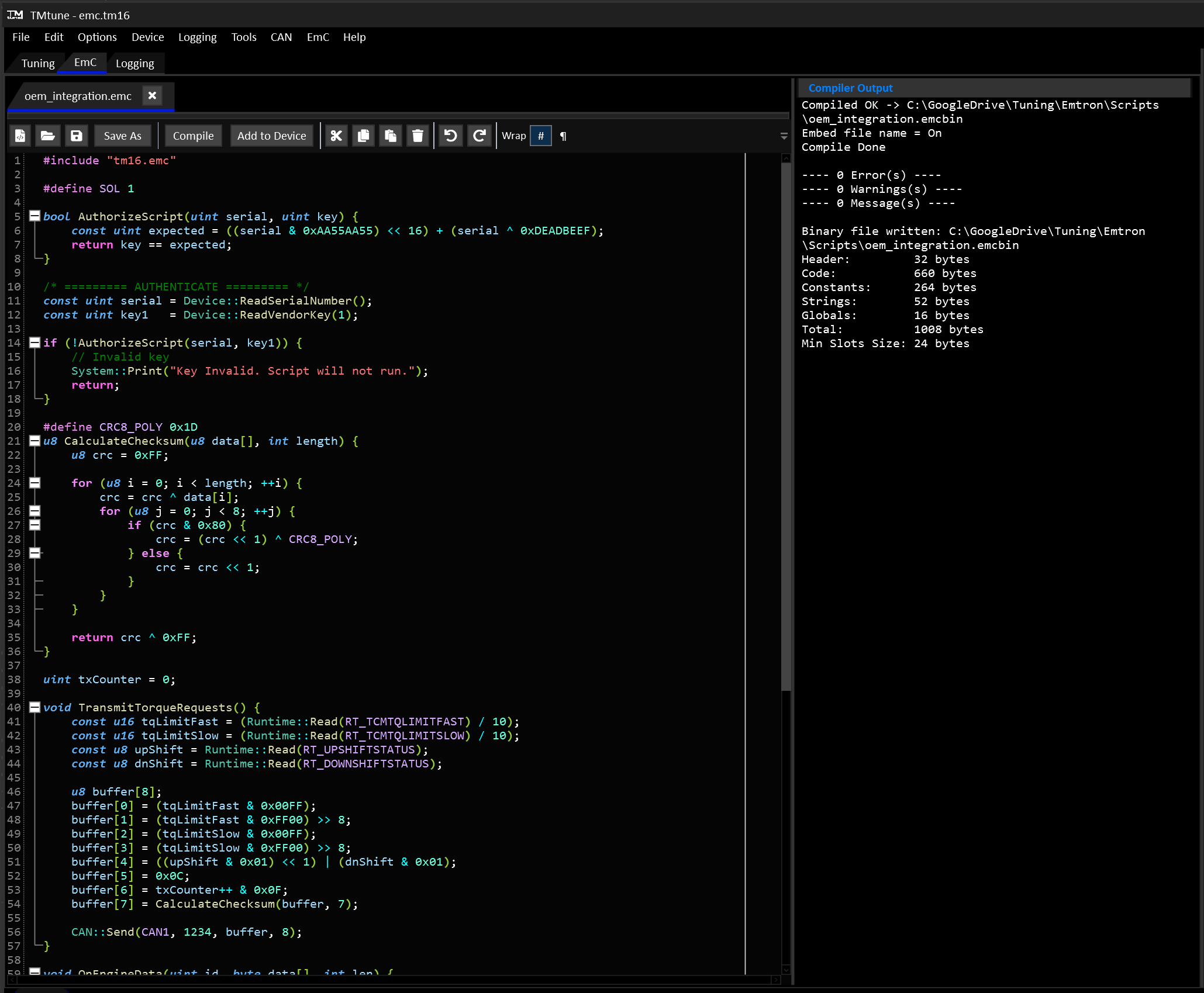
Subsections of Scripting
EmC Language
EmC is a statically-typed, heap-less, C-style scripting language for memory-constrained 32-bit embedded systems. Source files (.emc) compile to a compact bytecode binary (.emcbin) that runs on a stack-based virtual machine with no external dependencies and no runtime heap allocation.
The syntax is close to C. Most C code that avoids pointers, the heap, and the standard library will look familiar.
1. Program Structure
There is no main function. Top-level statements execute in source order when the script runs.
System:: is the namespace for functions provided by the host application, called native functions. A host can also group natives under namespaces of its own. See Native functions.
Functions and classes may be declared at the top level. They can be referenced before their declaration appears in the file (see Forward references).
2. Comments
EmC supports C-style single line and block comments.
3. Types
EmC is a statically typed language. All data types are known at compile time, making execution faster and safer.
| Keyword | Alias | Meaning | Width |
|---|---|---|---|
void | no value (return type) | - | |
bool | true / false | 1 byte | |
char | s8 | signed 8-bit integer | 1 byte |
byte | u8 | unsigned 8-bit integer | 1 byte |
short | s16 | signed 16-bit integer | 2 byte |
ushort | u16 | unsigned 16-bit integer | 2 byte |
int | s32 | signed 32-bit integer | 4 byte |
uint | u32 | unsigned 32-bit integer | 4 byte |
float | f32 | 32-bit IEEE-754 | 4 byte |
string | immutable text constant | ref |
The alias column is just another way to declare the same keyword: s8 and char compile to exactly the same type, so they mix freely and error messages always report the char/byte/… name.
Aliases are provided for convenience as they are a little more descriptive than the classical type names.
char and byte are numeric types, not a distinct character type. Individual character literals are not supported, so an integer must be used.
string is a reference to a compile-time constant. String variables and string native parameters can only ever hold a literal or another string constant. For mutable text, use a byte array (see Strings).
4. Literals
null, NULL, and nil are all accepted and evaluate to integer 0.
An integer literal without a suffix is an int. Add U to make it a uint, as in C. This matters in two places: a plain literal assigned to a uint variable warns about an implicit cast, and an expression is only compiled with unsigned arithmetic and comparisons when one of its operands is unsigned, so x > 0U and x / 2U behave correctly for a uint x above 2147483647. A literal larger than 4294967295 is a compile error. An unsuffixed literal above 2147483647 keeps its bit pattern and wraps negative as an int, with a warning unless it is being assigned to a uint (so uint mask = 0xFFFFFFFF; is fine) or negated.
String literals use double quotes. There are no escape sequences: "\n" is a backslash followed by n, not a newline.
5. Variables
All variables are zero-initialized if no initializer is given.
Scope
- Variables declared at the top level are globals.
- Variables declared inside a function or block are locals.
- Blocks (
{ ... }) introduce a new scope. A local is visible from its declaration to the end of its enclosing block.
const
const marks a variable read-only after its initializer runs. Writing to it later is a compile error.
A const array must be initialized where it is declared, and its elements can’t be written after that. Assignment, compound assignment and ++/-- on an element are all compile errors. This works well for lookup tables:
A const array can only be passed to a const array parameter (see “Array Parameters”).
Naming Style
EmC enforces no naming convention. One common pattern is UpperCamelCase for functions and global variables and lowerCamelCase for locals and parameters, which makes a name’s scope visible at a glance and matches how the native functions are named. The compiler accepts any style, and the choice is entirely yours.
6. Operators
All basic mathematical and bitwise operations are supported.
Arithmetic
Important
Integer division and modulus by zero halt the VM with a “Division By Zero” error. Float division by zero also halts.
Bitwise
Comparison
A comparison always produces a bool.
Logical
Assignment
There is no %=, <<=, or >>=.
Increment / Decrement
Both prefix and postfix forms work on a variable, a class field or an array element:
A postfix ++ or -- has to be the whole expression, as in i++; or int old = counts[b]++;. Using it inside a larger expression, such as a + i++, is a compile error. The index is evaluated once, so counts[Next()]++; calls Next() once.
Narrow types wrap at their own width:
Ternary
Behaves like a single line if/else statement.
Precedence
From tightest to loosest binding:
.[]()(member, index, call)!~++--(unary)*/%+-&|^<<>><><=>===!=&&||?:(ternary)=+=-=*=/=&=|=^=(assignment)
Note that the bitwise and shift operators sit at the same level as + and -. Parenthesize when mixing them with arithmetic.
7. Type Conversions
Numeric types convert implicitly across signed, unsigned, and float categories as needed by an assignment, argument, or operator. There is no explicit cast syntax.
A function call’s return value converts the same way as any other value, so float f = count(); converts an int result to float and int n = 2 * ratio(); converts a float result to int.
The compiler warns when a float is converted to an integer type, because the fractional part is lost. This covers declarations, assignments, arguments, return values and array indexes. Other conversions, such as signed to unsigned, don’t warn by default.
Mixing int and float in arithmetic gives a float, as in C. The value keeps its fraction until it is stored, passed or returned, so int n = i * f * 4; only converts to int once, at the end. When the target is a float, the whole expression is worked out in float, including integer division. So float h = i / 2; with i = 1 gives 0.5, not 0.
Bitwise operators and switch need integer values, so a mixed expression like (i + f) & 3 is a compile error.
Storing a value in a char, byte, short or ushort wraps it to that type’s range, as in C. That happens at every store: a declaration, an assignment, a compound assignment, ++/--, an argument, and a return value. Arithmetic in between is done in int, so a result is only cut down when it’s stored. This makes decoding a signed 16-bit value from two bytes work as expected:
There is no integer overflow or wraparound detection. Arithmetic that exceeds a type’s range wraps silently.
8. Control Flow
if / else if / else
while
A while loop will continue as long as the condition is true.
There is no do/while.
for
A for loop has an initializer, condition, and update expression. The loop will continue as long as the condition is true.
All three clauses are optional. Any of them may be left empty, and for (;;) is an infinite loop.
break & continue
continuewill skip the rest of the loop body and continue to the next loop iteration.breakexits the loop immediately.
break and continue work in while and for loops.
switch
The controlling expression is an integer (float is rejected). case labels are integer literals and must be unique. default is optional. A case without a break falls through to the next case, as in C.
A case with no body falls straight into the next one, which is how several values share a single handler:
A case that has a body but no break runs its own body and then continues into the next case:
Info
switch statements are much more efficient than long if/else chains. They use a jump table to very quickly jump to the correct case label, rather than checking every entry for a match. The tradeoff is they produce more compiled binary size for large ranges.
A switch statement has to produce a jump table entry for every value between its lowest and highest case label value. This means that for large value ranges with a low number of case labels, the compiled output will be huge compared to if/else. The number of case labels has no effect on performance.
The compiler will output a warning if the number of case labels is less than half the value range.
9. Functions
- Scalar parameters are passed by value.
- A non-
voidfunction mustreturna value. - Calling with the wrong number of arguments is a compile error.
- Recursion is supported.
- A bare
return;in top-level code ends the script early. Destructors still run for every class instance declared before it. Returning a value from top-level code is a compile error.
Forward References
A top-level function or class may be used before it is declared in the file. This allows mutual recursion:
Array Parameters
An array parameter is written T name[] or T *name (equivalent). The array’s size is not part of the parameter type, so pass the length as a separate argument. A variable index used inside the function is still checked at runtime against the caller’s actual array, the same as any other array (see “Bounds checking” in the Arrays section).
Passing a non-array where an array parameter is expected, or an array of the wrong element type, is a compile error. So is giving the parameter a size (int values[4]).
Inside the function the parameter is used exactly like an array: index it, or pass it on by name to another array parameter, script or native. It cannot be used as a value on its own.
Declare an array parameter const when the function only reads it. A const parameter can’t be written inside the function, and it accepts both const and ordinary arrays. A const array can only be passed to a const parameter, since an ordinary parameter could write to it. The same applies when a function passes its own const parameter on.
Class parameters
See Classes.
10. Arrays
- Array size is fixed at compile time.
- If an initializer list is present, its length must match the declared size exactly.
int a[3] = {1, 2};is a compile error. - Without an initializer, every element is zero.
Indexing and assignment
Packed storage
char/byte arrays pack 4 elements per 4-byte slot; short/ushort arrays pack 2 per slot. This is transparent to the script; index them normally.
Bounds checking
A literal out-of-range index is a compile error, including a negative one:
A variable or computed index is checked at runtime instead. An out-of-range access halts the VM with an “Array Index Out Of Bounds” error rather than reading or writing whatever happens to sit next to the array:
This covers array parameters too: a function indexing a T name[] parameter with a variable index is checked against the size of whatever array the caller actually passed in, even through several levels of forwarding. It also covers an array field declared inside a class, however it’s reached: directly, through a class-typed parameter, or through a composed/embedded instance. It does not cover what a native function does with an array you pass it. See Native functions.
Bare array references
An array name used without an index has no value. It cannot be assigned to a scalar, returned as a scalar, or passed as a scalar argument. Pass it only to an array parameter (with a length) or index it.
11. Strings
String literals are immutable compile-time constants. Use them directly with the print natives:
For text you need to build or modify at runtime, use a byte buffer and the string natives. Every string native takes an explicit capacity, C snprintf-style. Nothing grows a buffer for you.
Notes and limits:
StrCopy/StrAppendtake astringconstant as the source, not anotherbyte[]buffer.- A freshly declared buffer is zero-filled, so
StrLengthon an untouched buffer is 0. - Content that does not fit the capacity is truncated and null-terminated.
12. Classes
Classes are supported for advanced data structures.
Fields
Declared in the class body. Each instance gets its own copy.
Methods
- Inside a method,
this.fieldand a barefieldname both refer to the current instance’s field. - A method can call a sibling method on the same instance with
this.method().
Constructors
ClassName(params) { ... }. A class has at most one constructor. It runs when an instance is declared with an argument list:
Fields are always zero-initialized first, before the constructor body runs. A class with no constructor is declared without parentheses:
Declaring an instance of a class that has a constructor without an argument list compiles, but produces a warning.
Destructors
~ClassName() { ... }. Runs automatically when the instance goes out of scope:
- A local instance is destroyed at the end of its enclosing block.
- Multiple instances in the same scope are destroyed in reverse declaration order (LIFO).
- Global instances are destroyed once, at script end, in reverse declaration order.
Passing instances
Pass an instance to a function or method by reference with ClassName *param. The callee can call methods on it and read or write its fields, including compound assignment.
Passing an instance of the wrong class, or a non-instance, is a compile error. A bare instance name (no ., no method call, not passed to a class parameter) has no value and cannot be used as one.
Class-typed fields (composition)
A field may itself be a class instance. The embedded instance is laid out inline in its owner and reached with a chain of .:
- Nesting is unlimited:
a.b.c.xresolves as long as each step names a class-typed field. - Compound assignment works through the chain:
o.inner.value += 50;. - An embedded instance can be passed by reference like any other instance:
take(o.inner);wheretaketakesInner *i. - When an instance is created, each embedded field is zero-initialized and its field-default initializers run, outermost first.
- Destructors run automatically and in order: the owner’s destructor body first, then each embedded field’s destructor in reverse declaration order.
Limits:
- No member-initializer syntax. You cannot pass constructor arguments to an embedded field. Embedding a class whose constructor takes arguments is a compile error. A class with no constructor (or a parameterless one) is fine.
- No cycles. A class cannot contain itself, directly or indirectly (
class A { A a; }, orAholding aBthat holds anA). This is a compile error.
Not supported
- Inheritance. Every class is standalone. There is no subclassing.
- Class-typed return values. A function cannot return a class instance.
13. Namespaces
Namespaces are optional. They group top-level declarations under a name so they can be kept tidy and referred to explicitly. They have no runtime cost or effect: a namespaced global is still a plain global, and a namespaced function is still an ordinary function.
Refer to a member from outside with the :: scope operator:
- Unqualified access inside the block. Within
namespace Geometry { }, other members are visible without the prefix (area()can callgridSizeandPointdirectly). Names that don’t resolve inside the namespace fall back to the global scope. - Reopening. The same namespace name may be opened more than once, and the contents are merged.
- Forward references work across the whole file, exactly as they do at the top level.
- No nesting. A
namespacecannot be declared inside anothernamespace. - Native namespaces are reserved. A script cannot declare a namespace that the host’s natives use, and
Systemis always off limits. See Native functions. Mathis reserved for the built-in math functions. See Math functions.
14. Preprocessor
Runs on the token stream before parsing. Two directives are supported.
#include
- Path is resolved relative to the including file first. If it is not found there, any include directories set up by the host are searched in order. Absolute paths are used as is.
- Each file is included at most once, so diamond includes are safe.
- A circular include is a compile error, not a hang.
- A missing file is a compile error.
- Errors inside an included file are reported against that file’s own line numbers.
#define
Object-like macros only.
- A name is a macro only from its
#defineonward. - A macro body may reference an earlier macro, which is re-scanned and expanded.
- Self-referential and mutually-referential macros expand once and stop.
- An empty replacement is allowed and vanishes at the use site.
- Function-like macros (
#define SQ(x) ((x)*(x))) are a compile error. - There are no conditional directives (
#ifdef,#if,#endif,#undef). - A macro defined in an including file is visible inside included files.
15. Native functions
Native functions are provided by the host application. They give a script access to the device it runs on, for example printing, timing and communications. Which natives are available depends on the host. The reference set below is a common starting point.
Calling natives
Every native must be called through its namespace:
A bare Yield(10) is a compile error.
Most natives are in System. A host can group others under namespaces of its own, such as CAN above.
- A namespace used by any native is reserved, so a script cannot declare one with the same name.
Systemis always reserved. - Only the namespace is reserved, not the names inside it. With
CAN::Readavailable, a script is still free to declare its ownReadvariable or function, or aData::Readof its own.
If the script calls a native the host doesn’t provide, it still compiles, but halts with a “Native Function Not Resolved” error when the call runs.
Array arguments
Pass an array to a native by bare name, followed by its length:
The native trusts the length you give it. Its access to the array is not bounds checked, so never pass a length larger than the array.
A native that only reads an array takes it as a const parameter, and accepts both const and ordinary arrays. Passing a const array to a native that isn’t marked const is a compile error.
Callback parameters
Some natives take a script function as an argument, so the host can call back into the script later, for example when a CAN frame arrives. Pass the function’s bare name, with no parentheses:
A callback always returns void, and its parameters must match what the native expects. The compiler checks the parameter count, each parameter’s type, and whether it is an array, and reports a mismatch at the call site. Some natives accept any void function. A wrong parameter count is then only caught when the host calls it, which halts the script with a “Call Arg Count Error”.
An array parameter in a callback is only valid for the duration of the call. Index it or pass it on to another array parameter as usual, and copy anything you want to keep into a script array before returning.
Reference set
These natives are all in the System namespace, so Print is called as System::Print("hi").
| Signature | Purpose |
|---|---|
void SetError(int code) | Signal a recoverable error code to the host. |
void Print(string str) | Write a string, no newline. |
void PrintLine(string str) | Write a string and a newline. |
void PrintInt(int i) | Write an integer and a newline. |
void PrintFloat(float f) | Write a float and a newline. |
void PrintFormat(string str, float f) | Write a format string with one float (PrintFormat("v: %f", 3.14)). |
int StrLength(const byte buf[], int capacity) | Length up to the null terminator or capacity. |
void StrCopy(byte dest[], int destCapacity, string src) | Copy a string constant into a buffer, truncating to fit. |
void StrAppend(byte dest[], int destCapacity, string src) | Append a string constant onto a buffer’s content. |
void IntToStr(byte dest[], int destCapacity, int value) | Format an integer as decimal text into a buffer. |
bool StrEquals(const byte a[], int capA, const byte b[], int capB) | Compare two buffers’ null-terminated contents. |
void PrintBuffer(const byte buf[], int capacity) | Write a buffer’s null-terminated content. |
uint NowMs() | Host uptime in milliseconds. Wraps on overflow - compare with unsigned subtraction. |
uint NowUs() | Host uptime in microseconds. Wraps on overflow, typically much sooner than NowMs. |
void Yield(uint t) | Pause for t milliseconds. |
uint YieldUntil(uint lastTime, uint delay) | Fixed-period pause: sleeps until lastTime + delay, returns the new lastTime to pass back in next iteration. |
SetError
SetError(int) records an error code without halting the VM. The host application can read it after the script finishes. The last call wins. The default is 0.
16. Math functions
A set of math functions is built into the language under the Math namespace. They are part of the VM itself, so they are always available, whatever natives the host provides.
| Function | Result |
|---|---|
Math::Sqrt(x) | Square root. |
Math::Pow(base, exp) | base raised to exp. |
Math::Sin(x), Math::Cos(x), Math::Tan(x) | Trigonometric functions. x is in radians. |
Math::Asin(x), Math::Acos(x), Math::Atan(x) | Inverse trigonometric functions, in radians. |
Math::Atan2(y, x) | Angle of the point (x, y) in radians, in the range -pi to pi. |
Math::Exp(x) | e raised to x. |
Math::Log(x) | Natural logarithm. |
Math::Log2(x), Math::Log10(x) | Base 2 and base 10 logarithms. |
Math::Floor(x), Math::Ceil(x) | Round down / up to a whole number. |
Math::Round(x) | Round to the nearest whole number, halves away from zero. |
Math::Fmod(x, y) | Floating point remainder of x / y. |
Math::Abs(x) | Absolute value. |
Math::Min(a, b), Math::Max(a, b) | Smaller / larger of the two. |
All functions take and return float. An int argument is converted to float first, the same as passing it to a float parameter.
Abs, Min and Max are the exception: when every argument is an integer type they work in integers and return int, so int m = Math::Max(3, 7); is exact with no float round trip. If any argument is a float, including a mixed expression like i + 0.5, the whole call is done in float.
A domain error such as Math::Sqrt(-1.0) or Math::Log(0.0) produces NaN or infinity, as in C. It does not halt the VM.
17. Runtime Model and Limits
- No heap. Globals, locals, and call frames all live in one buffer supplied by the host. The VM never allocates at runtime.
- No whole-script size ceiling. Function entry points are 32-bit offsets, so a compiled binary can be as large as the host is willing to load. Two 16-bit limits do apply: a single
if,else, loop body, orswitchcannot span more than 64 KB of bytecode (the compiler reports “Too much code to jump over”), and the VM’s data area (globals plus stack) is capped at 65,535 slots, which is 256 KB. - Fixed stack. The host sets the stack size. Deep recursion or large local arrays can exhaust it (“Stack Overflow”).
- Bounds checking. Stack overflow/underflow and out-of-range pointer dereferences are caught and halt the VM rather than corrupting memory. The host can disable this for targets that cannot afford the checks. A local, global, or array-parameter index that runs off the end of its array is also caught (“Array Index Out Of Bounds”). See “Bounds checking” under Arrays.
- Division by zero halts the VM (“Division By Zero”) for integer and float operands.
- No overflow detection. Arithmetic wraps silently.
- No exceptions. There is no
try/catch/throw. A genuine runtime error halts the VM. UseSetErrorfor recoverable conditions. - No string escape sequences.
- Language version. A compiled binary records the language version it was built for. A VM won’t load a binary from a newer version, for example a 0.3 script on a 0.2 VM, since it may use instructions that VM doesn’t have. Binaries from older versions still load. Recompile a script with the matching compiler, or update the VM.
Runtime errors
Every run ends with a status. “End” means the script finished normally. Anything else is an error that stopped it. The common ones are:
| Error | Cause |
|---|---|
| Division By Zero | An integer or float division, or a modulus, by zero. |
| Array Index Out Of Bounds | A variable array index was outside the array. |
| Stack Overflow | The script ran out of stack, usually from deep recursion or large local arrays. |
| Native Function Not Resolved | The script called a native the host doesn’t provide. |
| Call Arg Count Error | The host called a callback with the wrong number of arguments. |
| Stack Underflow, Pointer Out Of Bounds, Unknown Instruction | A damaged binary, or a problem in the VM or host rather than in the script. |
A binary can also be refused when it’s loaded, before any of it runs: “Unsupported Version” for a binary compiled for a newer language version, and “Invalid Script” for one that is malformed or fails its checksum.
18. Complete Example
Output:
Script Management
The TCM hosts a powerful in-house developed scripting language called EmC. This allows users to write their own functionality to do almost anything from advanced CAN integrations to special control functions for transmission or vehicle systems.
Info
EmC requires a Developer License and must be activated using the Build Manager on each device.
EmC
EmC is a statically-typed, heap-less, C-style scripting language for 32-bit embedded systems.
Source files (.emc) compile to a compact bytecode binary (.emcbin) that runs on a stack-based virtual machine inside the host device.
Intellectual Property
EmC is compiled before it reaches the hardware, so developers can distribute their own proprietary compiled code without the user having or requiring access to the source code.
Once an EmC binary is uploaded to the device, it cannot read back and exported for redistribution without the original file.
Because EmC is statically typed, a lot of error checking is done at compile time, reducing the chance of runtime errors or undefined behavior.
See EmC language documentation for more detail.
- Up to 8 compiled scripts can live in the TCM at once.
- All scripts total 1MB of compiled binary size.
- Scripts can be assigned up to 32KB of stack memory each.
- Each script runs on it’s own thread.
- Scripts can interact with each other by reading and writing Runtime channels.
Activation
Dealers with a current EmC Developer License can purchase and activate the EmC Application Build on a device.
Once EmC has been enabled for your device’s serial number, use the Build Manager to activate it.
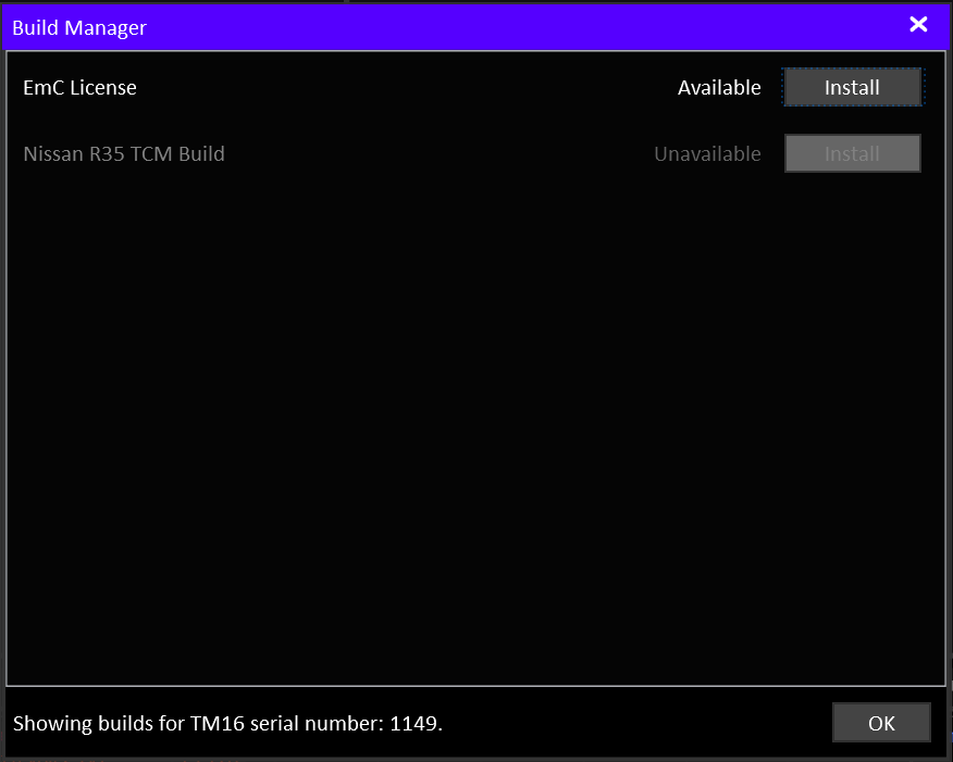
EmC IDE
The EmC development environment is accessed via the “EmC” tab when a cal file is open or a TCM is online. The environment can be opened without a device or cal file from the EmC menu.

Compiling
Press Compile on the toolbar to compile the script (along with any emc files it includes). The compiler result is shown on the RHS.
On a successful compilation, the script to be added to the device script management list by clicking Add to Device.
Errors shown in the compiler output will also he highlighted in red in the editor panel. Warnings shown in the compiler output will also he highlighted in yellow in the editor panel.
Device Script Management
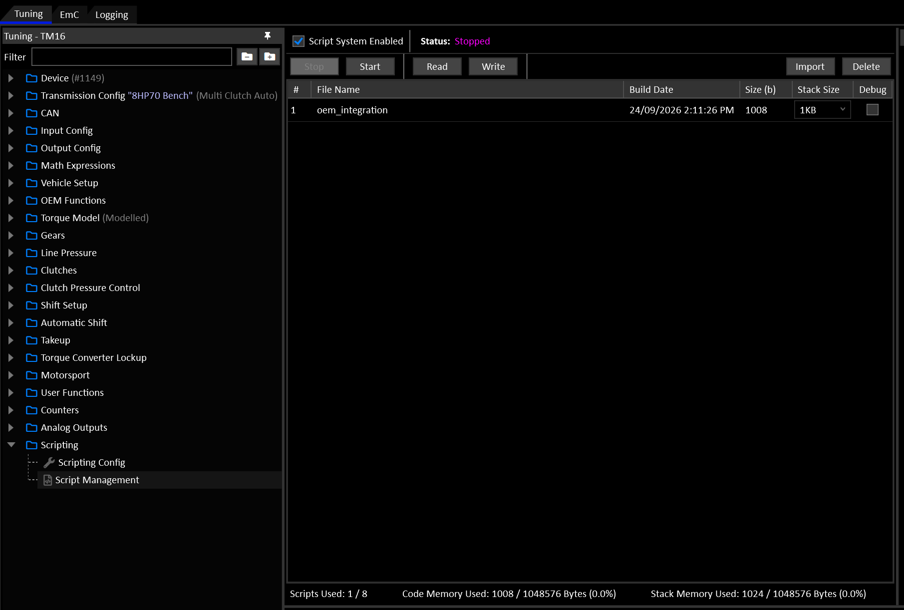
The Script Management view shows the scripts either in the device or staged for upload.
Info
In order to upload changes to the script memory, the script system must be stopped.
Stophalts the script system, ready to upload changes.Startstarts a halted system and starts all scripts running.ReadReads the script memory from the device.Writesends the current script memory and configuration to the device and starts the system.Importimports a compiled EmC binary file (.emcbin). This can be used to import compiled 3rd party scripts without the source files.Deleteremoves the selected script file from the list.
Each Script has it’s own status runtime. A successfully running script’s status will show “OK”.
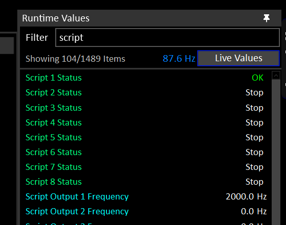
System Functions
This is a reference for every native function callable from a EmC script running on the TCM including:
- General-purpose functions under
System::for debugging and time management. - TCM-specific functions under
Runtime::,Torque::,Device::,CAN::andOutput::for reading live device state, supplying engine torque, talking to the CAN bus and driving script-controlled outputs.
Quick Reference
Strings & Debugging (System::)
| Function | Signature | Purpose |
|---|---|---|
| System::Print | void Print(string str) | Debug-print a string, no newline |
| System::PrintLine | void PrintLine(string str) | Debug-print a string plus newline |
| System::PrintInt | void PrintInt(int i) | Debug-print an integer |
| System::PrintFloat | void PrintFloat(float f) | Debug-print a float |
| System::PrintFormat | void PrintFormat(string str, float f) | Debug-print a format string with one float |
| System::PrintBuffer | void PrintBuffer(byte buf[], int capacity) | Debug-print a byte buffer’s null-terminated content |
| System::StrLength | int StrLength(byte buf[], int capacity) | Length of a buffer’s content up to its null terminator |
| System::StrCopy | void StrCopy(byte dest[], int destCapacity, string src) | Copy a string constant into a buffer, truncating to fit |
| System::StrAppend | void StrAppend(byte dest[], int destCapacity, string src) | Append a string constant onto a buffer’s content, truncating to fit |
| System::IntToStr | void IntToStr(byte dest[], int destCapacity, int value) | Format an integer as decimal text into a buffer |
| System::StrEquals | bool StrEquals(byte a[], int capacityA, byte b[], int capacityB) | Compare two buffers’ null-terminated contents |
Time
| Function | Signature | Purpose |
|---|---|---|
| System::NowMs | uint NowMs() | Device uptime in milliseconds (wraps every ~49.7 days) |
| System::NowUs | uint NowUs() | Device uptime in microseconds (wraps every ~71.58 min) |
Script Yielding
| Function | Signature | Purpose |
|---|---|---|
| System::Yield | void Yield(uint t) | Pause the script for t milliseconds |
| System::YieldUntil | uint YieldUntil(uint lastTime, uint delay) | Fixed-period pause that returns the updated lastTime for the next call |
Runtime Channels (Runtime::)
| Function | Signature | Purpose |
|---|---|---|
| Runtime::Read | int Read(uint id) | Read a live channel value as an integer with the decimal point removed (123.4 reads as 1234) |
| Runtime::ReadReal | float ReadReal(uint id) | Read a live channel value as a float in real units |
| Runtime::Write | bool Write(uint id, int value) | Write a writeable channel value as an integer with the decimal point removed |
| Runtime::WriteReal | bool WriteReal(uint id, float value) | Write a writeable channel value as a float in real units |
Torque Model (Torque::)
| Function | Signature | Purpose |
|---|---|---|
| Torque::GetSupplied | float GetSupplied() | Read Engine Torque (Supplied) in Nm |
| Torque::SetSupplied | void SetSupplied(float tqSupplied) | Supply Engine Torque (Supplied) when Torque Model Source is Script |
| Torque::GetAvailable | float GetAvailable() | Read Engine Torque (Available) in Nm |
| Torque::SetAvailable | void SetAvailable(float tqAvailable) | Supply Engine Torque (Available) when Torque Model Source is Script |
| Torque::GetDriverDemand | float GetDriverDemand() | Read Driver Demand Torque in Nm |
| Torque::SetDriverDemand | void SetDriverDemand(float tqDriver) | Supply Driver Demand Torque when Driver Demand Source is Script |
CAN Bus (CAN::)
| Function | Signature | Purpose |
|---|---|---|
| CAN::SetupNode | bool SetupNode(uint node, bool enable, uint bitrateSelect, bool termination, bool listenOnly) | Enable/disable a CAN node and set its bitrate, termination and listen-only mode |
| CAN::Send | void Send(uint node, uint id, byte buffer[], int length) | Send a raw frame on CAN 1 or CAN 2 |
| CAN::Read | int Read(uint node, uint id, byte buffer[], int length) | Poll the latest received frame for a node/id pair |
| CAN::Subscribe | void Subscribe(uint node, uint idMatch, uint idMask, func(uint id, byte data[], int length) handler) | Register a callback for received frames matching an id/mask |
| CAN::Unsubscribe | void Unsubscribe(uint node, uint idMatch, uint idMask) | Cancel a subscription registered with the same node/match/mask |
| CAN::Poll | int Poll() | Fire the handlers for any frames received since the last call |
Output Control (Output::)
| Function | Signature | Purpose |
|---|---|---|
| Output::SetActiveLevel | void SetActiveLevel(byte outputId, int level) | Set a script output’s active polarity (0 = active-low, 1 = active-high) |
| Output::SetEffectiveResistance | void SetEffectiveResistance(byte outputId, float ohms) | Tell current control the load’s resistance |
| Output::SetFreq | void SetFreq(byte outputId, float frequency) | Set a script output’s PWM/current-chop frequency in Hz |
| Output::SetDuty | void SetDuty(byte outputId, float dutyCycle) | Drive a script output in PWM mode at a fixed duty (0-100) |
| Output::SetCurrent | void SetCurrent(byte outputId, float milliAmps) | Drive a script output in closed-loop current control |
Device Information (Device::)
| Function | Signature | Purpose |
|---|---|---|
| Device::ReadSerialNumber | uint ReadSerialNumber() | Read the device’s serial number |
| Device::ReadVendorKey | uint ReadVendorKey(int keyId) | Read one of two vendor keys (keyId 1 or 2), typically used to lock a script to a specific device |
Calling Convention
Every native function is called through its namespace.
Calling a native bare (Yield(10);, Poll();) or through the wrong namespace (System::Runtime::Read(1);) fails to compile. Function names are case-sensitive and must match the names in this manual exactly.
A callback handler passed to CAN::Subscribe (a func-typed parameter) is the one exception: it’s a bare script function name, not called through any namespace - see CAN Receive Callbacks.
Runtime ids (the uint id arguments to the Runtime:: functions) are plain numbers assigned by the device’s .mdef. Rather than hard-coding them, #include "mtc.emc" and use the RT_ names it defines - see Include Files.
Every CAN:: function takes a node as its first argument, zero indexed: 0 is CAN 1 and 1 is CAN 2. CAN::Subscribe and CAN::Unsubscribe also accept 2 for both buses; everywhere else 2 is rejected. The include file provides CAN1, CAN2 and CAN_BOTH for these.
Included Device Definition Files
Device header file(s) ship along side the compiler, so a script can refer to channels, buses, bitrates, etc by name instead of by number. Include it at the top of the script:
The file name is the device’s name in lower case: tm16.emc for the TM16. The compiler already knows where the shipped headers live, so the plain file name works wherever the script itself is saved. Including the same file more than once (e.g. from two of your own include files) is harmless.
| Group | Names | Meaning |
|---|---|---|
| Constants | LOW, HIGH | 0 and 1, for Output::SetActiveLevel |
| CAN buses | CAN1, CAN2, CAN_BOTH | The node argument of the CAN:: functions (0, 1, 2) |
| CAN Bitrates | CAN_BITRATE_125K, CAN_BITRATE_250K, CAN_BITRATE_500K, CAN_BITRATE_1M, CAN_BITRATE_CUSTOM | The bitrateSelect argument of CAN::SetupNode |
| Runtime Channels | RT_ENGSPD, RT_GEAR, RT_BATTVOLTS, … | The Runtime ID of every channel, for the Runtime:: functions |
A runtime channel’s name is RT_ followed by its abbreviation in upper case (the “Engine Speed” channel becomes RT_ENGSPD). Each define carries the channel’s full label as a trailing comment, so the quickest way to find a channel is to open the header and search for the channel name.
You are free to define your own constants too.
The header only provides names - it doesn’t change what any function does. A channel that isn’t writeable still refuses Runtime::Write whether it’s addressed by RT_ name or by number.
Info
#define is used in preference to const uint declarations because unused defines have no effect on the compiled output. If you create 100 variable declarations (const or not), you will add 100 variables to the compiled script binary, that must also take up space on the stack when running.
String/Debug Output
Print, PrintLine, PrintInt, PrintFloat, PrintFormat and PrintBuffer all write to the same destination: a debug message sent to a connected PC over the device’s Ethernet port, rate-limited so a busy loop can’t flood it. None of them do anything unless all of the following are true:
- The PC is connected to the device and has debug output active, AND
- The specific script has its “Debug” option enabled in its configuration.
[IMPORTANT] Always disable debug when it’s no longer required.
str in Print/PrintLine/PrintFormat must be a string - a compile-time string constant, not a byte[] buffer. Use PrintBuffer for buffer content instead (see String Buffers).
System::Print
Prints a string literal with no newline.
System::PrintLine
Prints a string literal followed by a newline. Use it for the last piece of a line built up from several Print/PrintInt calls. An empty string "" is not accepted as an argument, so end the line with real text, or use PrintFormat with a \n in its format string.
System::PrintInt
Prints i as a single integer value.
System::PrintFloat
Prints f as a decimal float (%f format).
System::PrintFormat
Prints str as a printf-style format string with f as its one and only argument.so only a single %f-style specifier makes sense. Anything else in the string that consumes an argument is undefined, the same way a mismatched printf format is in C.
System::PrintBuffer
Prints buf’s contents up to its null terminator, or up to capacity bytes, whichever comes first.
See StringBuffers.
String Buffers
string constants are immutable and can’t be built or modified at runtime - for text a script assembles itself (formatting a value, building a label from CAN data, etc.) it needs a byte[] buffer instead, plus the five string natives that operate on it. All five are C snprintf-style: every one takes an explicit capacity and truncates rather than overflowing.
Two easy mistakes to make:
StrCopy/StrAppend’s source (src) is always astringconstant, never anotherbyte[]buffer. There’s no buffer-to-buffer append.- A
byte[]buffer can never be passed where astringparameter is expected. A freshly declared buffer is zero-filled, soStrLengthon one that’s never been written returns0.
System::StrLength
Scans up to capacity bytes for a \0 and returns how many bytes precede it: 0 if buf starts with \0, capacity if no terminator is found.
System::StrCopy
Copies src into dest, truncating and null-terminating to fit within destCapacity.
System::StrAppend
Appends src onto dest’s existing null-terminated content, truncating and null-terminating to fit within destCapacity.
System::IntToStr
Formats value as decimal text into dest, truncating and null-terminating to fit within destCapacity.
System::StrEquals
Returns true if a and b’s null-terminated contents are identical, each scanned up to its own capacity.
Timing
NowMs/NowUs read the device’s uptime from the same free-running hardware timer, but with different wrap periods.
Tip
Write comparisons the wraparound-safe way (unsigned subtraction) rather than assuming now only ever increases:
(uint)(now - start) >= threshold)
System::NowMs
Uptime in milliseconds. Wraps every ~49.7 days (2^32 milliseconds), which makes it the safer default for a script tracking longer-running state (e.g. time since ignition-on).
System::NowUs
Uptime in microseconds. Wraps every ~71.58 minutes (2^32 microseconds).
Because the two clocks wrap at different points, NowMs() and NowUs() / 1000 only agree with each other for the first ~71.58 minutes after boot - once NowUs has wrapped, NowMs keeps counting while NowUs has reset near zero, so don’t rely on them staying numerically related.
System::Yield
Pauses the calling script for t milliseconds, letting other threads (and the rest of the script scheduler) run. This is the standard way to pace a script’s own loop instead of spinning:
System::YieldUntil
A fixed-period yield: sleeps until lastTime + delay, then returns the new lastTime (lastTime + delay) for the caller to feed back in on the next iteration. Unlike Yield, which always sleeps for a fixed duration from now, this keeps a loop’s period accurate even if the loop body’s own work takes a variable amount of time each iteration:
The function takes and returns lastTime explicitly rather than updating it in place (EmC has no reference parameters) - always reassign the return value back onto the variable you pass in, or the period will drift.
Runtime Channels
Runtime channels are the live values used throughout the TCM (engine RPM, gear, clutch pressures, launch targets and so on). Each is identified by its Runtime ID, available by name as RT_... from the device’s include file.
Tip
See the Runtimes reference document for a list of all runtime channels, their #define names, factors, decimals etc.
Channels come in two flavours from a script’s point of view:
Read/Writework in the channel’s integer representation: the real value with its decimal point removed, so a channel displayed as123.4(one decimal place) reads as1234, and writing1234sets it to123.4. A channel with no decimal places reads and writes as-is.ReadReal/WriteRealwork in floating point units (123.4) and are the simpler choice unless you specifically want integer maths. The TCM is equipped with an FPU so floating point operations are trivial.
Reads of an ID that doesn’t resolve to anything return 0. Writes only succeed (return true) if the target channel is writeable. Lots of channels are computed outputs, not inputs, and will refuse the write.
Important
Channels driven by Input Functions such as Engine Speed must have their input assignment set to Script or they cannot be written to.
Runtime::Read
Reads the channel as an integer with the decimal point removed. Returns 0 if id is unknown.
Runtime::ReadReal
Reads the channel as a float in its real units. Returns 0 if id is unknown.
Runtime::Write
Writes value, an integer with the decimal point removed, to the channel. Returns true if the channel accepted the write, false if id is unknown or the channel is not writeable.
Runtime::WriteReal
Writes value, a float in the channel’s real units.
Returns true if the channel accepted the write, false if id is unknown or the channel is not writeable.
Torque Model
A script can supply engine torque to the TCM, e.g. when the ECU sends torque in a format the CAN setup can’t decode directly, or when torque needs to be calculated from other channels. See TCM Torque Model for how the TCM uses these values.
Torque::SetSuppliedandTorque::SetAvailableonly take effect while Torque Model Source is set to Script.Torque::SetDriverDemandonly takes effect while Driver Demand Source is set to Script.- In any other source mode the value is ignored.
Values are in Nm. The torque correction and offset tables (when enabled) are applied on top of the value the script supplies: Engine Torque Correction and Engine Torque Offset for Supplied and Available, Driver Demand Torque Correction and Driver Demand Torque Offset for driver demand. The Get functions return the final value after correction and offset. A supplied value is held until the script sets a new one, so a script that stops or faults leaves the TCM using its last torque values.
Important
Always set both Supplied and Available torque. If the ECU only provides one torque value, set it to both. If Engine Torque (Available) is left at 0, the TCM will think the engine has no torque available and request a full cut on every upshift.
Note
The torque channels can’t be written with Runtime::Write or Runtime::WriteReal. Use the Torque:: functions instead.
Torque::GetSupplied
Returns Engine Torque (Supplied) in Nm: the torque the engine is producing now, after any ignition retard or cuts. Works in every Torque Model Source mode.
Torque::SetSupplied
Supplies Engine Torque (Supplied) in Nm. Ignored unless Torque Model Source is Script.
Torque::GetAvailable
Returns Engine Torque (Available) in Nm: the torque the engine would be producing with no retard or cuts. Works in every Torque Model Source mode.
Torque::SetAvailable
Supplies Engine Torque (Available) in Nm. Ignored unless Torque Model Source is Script.
Torque::GetDriverDemand
Returns Driver Demand Torque in Nm. Works in every Driver Demand Source mode.
Torque::SetDriverDemand
Supplies Driver Demand Torque in Nm. Ignored unless Driver Demand Source is Script.
CAN Bus
Every CAN:: function takes a node as its first argument (0 indexed):
0= CAN 1,1= CAN 2Subscribe/Unsubscribealso accept2= both buses.
Node Setup
CAN::SetupNode
Configures and restarts a CAN node from the script, replacing the node’s settings from the calibration.
Returns true on success, false if node is not 0 or 1.
enable-falseturns the node off entirely (no transmit, no receive, termination off). The other arguments are still stored but have no effect until the node is enabled again.bitrateSelect0= Custom bit timing1= 125 kbit/s2= 250 kbit/s3= 500 kbit/s4= 1 Mbit/s- *Any other value leaves the bit timing as it was.
termination- switches the node’s on-board 120R termination resistor on or off.listenOnly-trueputs the node in silent mode: it receives frames but never transmits or acknowledges, and the node’s configured CAN transmit channels are stopped. Use it to read from a bus the TCM must not disturb.
Calling it restarts the node, so any frames in flight on that bus are lost. Call it once at script start, NOT from inside the loop. The new settings are not saved to flash by the call itself, so a script that depends on them should apply them every time it starts.
Raw CAN I/O (polling)
Send/Read are the simple, polling pair. Both target one bus, so node must be 0 or 1. 2 is rejected (Send does nothing, Read returns -1).
CAN::Send
Queues a CAN message with identifier id and the first length bytes of buffer (at most 8) for transmission on node. The call returns as soon as the frame is queued; it does nothing if node is not 0 or 1 or length is 0.
CAN::Read
Copies the most recently received frame with identifier id on node into buffer, up to length bytes, and returns the number of bytes copied. Returns -1 if no frame with that id has been seen on that bus yet.
The device keeps the latest frame for each node/id pair a script has asked about, and each Read call copies out of that store, so reading a frame doesn’t consume it: the same frame is returned again until a newer one arrives. The system holds a fixed number of node/id pairs (16, shared across all running scripts); once it’s full, Read on a pair it isn’t already tracking returns -1. This is fine for a handful of ids a script cares about. If you need every frame on a range of ids, or lower latency, use the callback API below instead.
CAN Receive Callbacks
CAN::Subscribe registers a script function to be called for every received frame whose id matches an id/mask pair, on CAN 1, CAN 2 or both. One subscription can cover many ids (see Id/Mask Matching). Handlers don’t run the instant a frame arrives: matching frames are queued for the script, and CAN::Poll() - called from the script’s own loop - runs each handler in turn on the script’s own thread. This means a callback can never delay real CAN traffic, but also means it only ever fires when the script calls CAN::Poll().
CAN::Subscribe
Subscribes a handler to a range of CAN messages:
node-0= CAN 1,1= CAN 2,2= both (CAN1,CAN2,CAN_BOTHfrom the include file).idMatch/idMask- a frame matches when(frame.id & idMask) == (idMatch & idMask). A mask of0matches every id on the node.handler- a bare script function name (no parentheses, no namespace), which must be declared with exactly this signature:
id is the received frame’s identifier, data holds its payload and length is how many of those bytes are valid (0-8). A handler with the wrong parameter count or types is rejected at compile time.
data is only valid until the handler returns. Index it, or pass it straight on to another function that takes a byte array (such as CAN::Send), but copy it into a script-declared array if you need the bytes afterwards. Each frame delivered to a handler also uses a little extra script stack on top of the handler’s own locals, so a script running very close to its stack limit can halt with a stack-overflow fault on delivery rather than silently missing the callback.
Calling Subscribe again with the same node/idMatch/idMask replaces the existing subscription’s handler rather than adding a second one.
CAN::Unsubscribe
Removes a subscription. Pass the exact same three values it was registered with.
CAN::Poll
Runs the handlers for every matching frame received since the last call, oldest first, and returns how many handlers were fired. A subscribing script must call it once per loop iteration, before yielding, or queued frames simply sit until the next call.
The queue holds a fixed number of frames per script. If a script falls behind a busy bus (e.g. it’s blocked doing other work), the oldest undelivered frames are dropped rather than the queue growing. Keep the loop tight and call Poll() regularly if you’re subscribing to high frequency message(s) or a wide mask. Calling Poll() from inside a handler (directly or indirectly) does nothing and returns 0.
Id/Mask Matching
The match is a bitwise AND against both sides, not a range check:
- Bits set in
idMaskare the ones that must match. - Bits clear in
idMaskare don’t-care and match any value.
A few common patterns:
The frame’s actual ID is always passed to the handler as its first argument, so a single wide-mask subscription can still tell which specific id triggered each call:
Output Control
Script outputs are a dedicated pool of up to 24 output channels that can be used to drive solenoids etc.outputId ranges from 1-24, not 0-based. ID 0 or anything above 24 resolves to nothing and does nothing.
Each output has to be assigned to a physical pin in the device’s configuration before a script can usefully drive it. An unassigned output accepts every call here without error but has no effect on hardware.
Info
The script has no way of knowing which physical output the user assigned to a given Script Output.
Eg: Script Output 1, with ID 1, maybe be assigned to drive Solenoid Output 7 (or any other output pin by the end user).
Info
SetDuty and SetCurrent set the output’s drive mode. Calling one switches the output into that mode and zeroes the other’s setpoint, so the two are mutually exclusive per output.
Whichever was called most recently wins.SetFreq applies to both modes.
Output::SetActiveLevel
Sets whether the output is driven active-high (1) or active-low (0).
LOW and HIGH definitions are in the device include file.
Output::SetEffectiveResistance
Auxiliary Outputs Only
Tells the current control system the resistance of the connected load. Used to help translate the current target into a drive duty. Only relevant in current-control mode when the output is assigned to an auxiliary output rather than a solenoid output.
Info
If the output’s effective resistance is set to 0 (Recommended and default), the system will work it out on it’s own. The only drawback is that the first application of the solenoid may take a few extra milliseconds to settle on the current target.
Tip
Where possible, preference using the solenoid outputs, not auxiliary outputs to drive current-controlled loads.
Output::SetFreq
Sets the output’s switching frequency in Hz:
- PWM rate in PWM (duty) mode.
- Base frequency in current-control mode.
PWM Range: 0.5 - 20000 Hz
Current Control Range: See below
Current Control Frequency
When an output is in current control mode, it’s frequency must be one of the following options:
- 110 Hz
- 200 Hz
- 300 Hz
- 400 Hz
- 500 Hz
- 600 Hz
- 700 Hz
- 800 Hz
- 900 Hz
- 1000 Hz
- 2000 Hz
- 3000 Hz
- 4000 Hz
PWM Mode Frequency
In PWM mode, any frequency up to 20000 Hz (20 KHz) is fine.
Once the duty cycle has been set, putting the output into fixed PWM mode, the frequency can be changed at will, even without updating the duty cycle again. This makes it possible to do variable frequency outputs such as a tacho output.
Output::SetDuty
Puts the output in fixed-duty PWM mode at dutyCycle percent (0-100) and clears any current target.
Output::SetCurrent
Puts the output in closed-loop current-control mode with a target of milliAmps and clears any duty setpoint.
Output Current Range
- Solenoid Outputs in single channel mode can command up to 1.5A.
- Solenoid Outputs in paired channel mode can command up to 2.7A.
- Auxiliary Outputs can command up to 5A. (high side or low side).
Info
Solenoid Outputs are the preferred output for current controlled loads.
Device Identity
A common use is locking a script to a specific device or vendor: compare the serial number and/or a vendor key that only the vendor knows and gives to the user, against an expected value at script start and refuse to run if it doesn’t match.
Device::ReadSerialNumber
Returns the device’s serial number.
Device::ReadVendorKey
Returns one of two general-purpose 32-bit calibration values (“Script Vendor Hardware Key 1/2”), set like any other calibration value. keyId is 1 or 2; any other value returns 0.
Info
The Script Vendor Hardware Key # variables are kept at the device level. This means that uploading a cal file with different values in the keys, will not change the values in the device. They will be ignored from the cal file data. This stops the sharing of cal files that run the same scripts from breaking script execution when uploaded.
Tuning
Subsections of Tuning
Emtron ECU Integration
This document details the steps required for the TCM and ECU to integrate with each other.
Minimum ECU Firmware Version: 2.21.0
TM16 to Emtron ECU CAN Protocol
The TM16 CAN protocol uses ID’s in the range of 336 to 345 (0x150 to 0x159). Care must be taken to ensure that no other devices are using ID’s withing that range.
Channels controlled by Input Functions (eg: Engine Speed) must have their input source set to CAN.
Transmission Channels
The following channels are transmitted by the TCM:
- Gear
- Gear Request (Next Gear)
- Input Shaft Speed
- Output Shaft Speed
- Torque Limit (Slow / Throttle)
- Torque Limit (Fast / Ignition)
- Up Shift Switch
- Down Shift Switch
- Transmission Fluid Temp
Engine Channels
The following channels are transmitted but the ECU:
- Engine Speed
- Manifold Absolute Pressure
- Throttle Area Demand
- Pedal Position Demand
- Engine Torque (No Reductions)
- Engine Torque (Final)
- Driver Demand Torque
- Brake Switch
- Engine Temperature
- Idle Target
- Idle Status
- Overrun Fuel Cut Status
- CE Light
TM16 Setup
- Set up the CAN Bus:
- Ensure the CAN Node is set to the same bitrate as the ECU (eg: 1 MBps)
- Ensure the CAN bus is correctly terminated
- Ensure proper CAN bus topology and wiring
- Assign a CAN Channel to: “Emtron Transmission Control Rx”
- Assign a second CAN Channel to: “Emtron Transmission Control Tx”
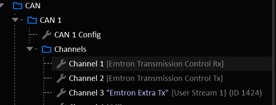
- Set the following input function sources to “CAN”:
- Engine Speed (Main)
- Throttle Position (Main)
- Pedal Position (Main)
- Manifold Absolute Pressure
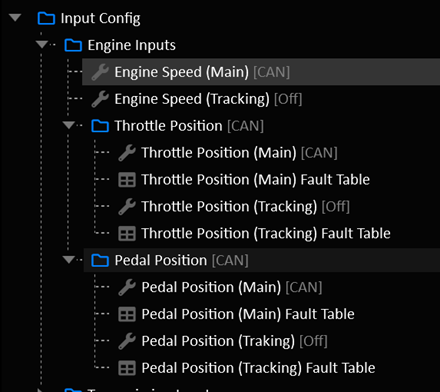
- Set the Torque Model to CAN:
- Torque Model Source
- Driver Demand Source
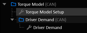
ECU Setup
- Set up the CAN Bus:
- Ensure the CAN Node is set to the same bitrate as the TCM (eg: 1 MBps)
- Assign a CAN Channel to “Emtron TM16”.

- Enable Gearshift Control: Emtron TM16
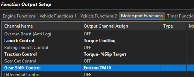
- Assign the following inputs to “CAN Bus OEM”:
- Input Shaft Speed
- Output Shaft Speed
- Gear Upshift Switch
- Gear Downshift Switch
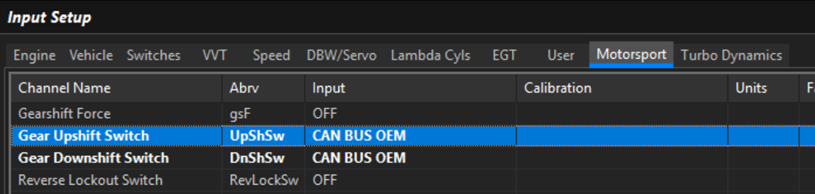
- Assign Gear Detection to “CAN Bus OEM”
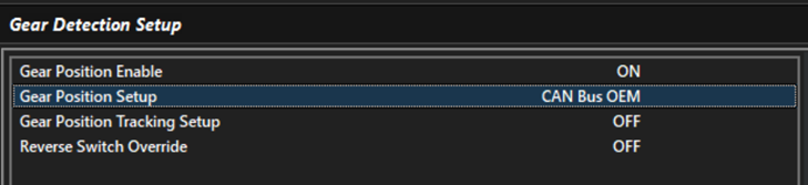
Fill in the Transmission Gear Ratio Table to match the TCM

Setup the Torque Model
- Normal Torque Model validation applies. Ensure the torque model is well sorted and frictional loss is validated.
- Set the CAN Bus Reported Torque Modifier Tables to zero unless you have a specific reason to change it.
It is critical that the ECU’s torque model is well sorted.
- In the TM16 Menu:
- Set TM16 Throttle Torque Gain to Zero
- Set TM16 Retard Torque Gain to Zero
- Set TCM WOT Torque Lockout Value to -1000 to disable
- Setup the Engine Cut Setup to suit your application
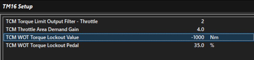
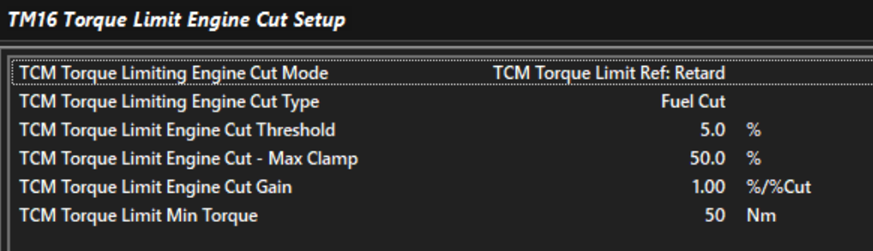
- Up Shift Setup:
- In Motorsport > Geashift Control TM16: Configure the upshift to your application.
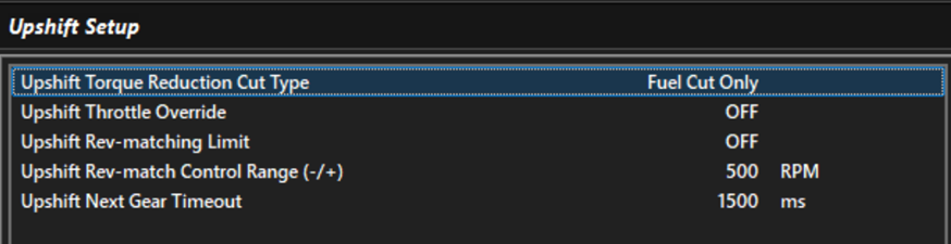
- Down Shift Setup:
- In Motorsport > Gearshift Control TM16, configure Downshift for your application.
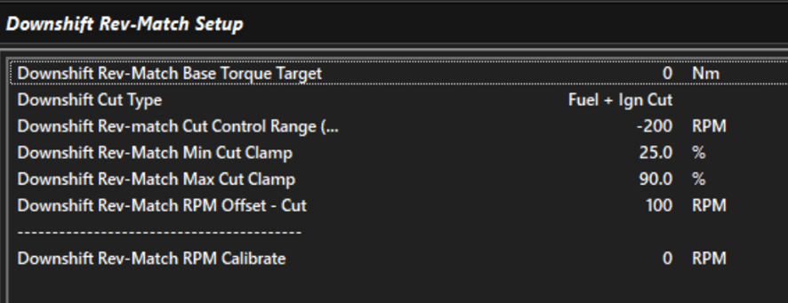
Most applications will use a Base Torque Target of 0 nm. This results in the engine holding itself at the rev match target until the clutch grabs it.
- Set up the Downshift Rev-Match Torque Target Margin Table:
This is the amount of torque applied at the start of the downshift to get the engine to the Rev-Match target. Engine torque is reduced to the Base Torque Target as the engine speed reaches the Rev-Match Target.

Important Notes
Upshift Switch
Upshift Switch is only transmitted when the TCM wants a torque limit during the shift. Otherwise, the Gear Request value will simply change to the next gear and the shift will progress without torque intervention. The ECU will abide by the torque limit specified by the TCM during a shit.
Downshift Switch
Downshift Switch is only transmitted when the TCM wants a Rev-Match. Otherwise, the shift will happen without intervention.
Rev Match Target
The ECU will calculate its own Rev-Match target RPM based on the Output Shaft Speed and Gear Ratio.
It is critical that the gear ratio table is correct.
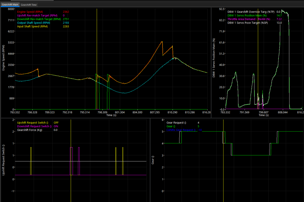
Automatic Shifting
Automatic shifting chooses the gear in Drive and Sport. It can also add automatic up shifts, down shifts and kickdown to Manual mode, for example to shift up at the rev limit or down before the engine lugs.
There are three ways to tell the TCM when to shift:
- Speed - Simple: one up shift table and one down shift table give the speed to shift at.
- Speed - Per Gear: a separate table for every up shift and down shift.
- Gear Request: the table holds the gear to be in.
Whichever is used, every automatic shift still has to pass the same checks as a manual shift (input shaft speed limits, Takeup, time since the last shift and so on, see When an Automatic Shift Is Blocked).
Enabling
Turn on Enable in Automatic Shift > Auto Shift Setup. The rest of the settings and the Drive Mode, Sport Mode, Manual Mode and Hill Control folders appear once it is on.
| Setting | Description |
|---|---|
| Enable | Turns automatic shifting on. Also needed for the Manual mode automatic shifts. |
| Table Mode | Speed - Simple, Speed - Per Gear or Gear Request, see Table Modes. |
| Speed Reference | The channel the speed tables are compared against, see Speed Reference. Not used in Gear Request mode. |
| Gear Request Table Hysteresis | Gear Request mode only, see Hysteresis. |
| Sport Tables | Off: Sport uses the Drive Mode tables. On: Sport uses the tables in the Sport Mode folder. |
| Up / Down Shift Switch Behaviour | What an Up Shift or Down Shift switch press does in Drive or Sport, see Up / Down Shift Switches in Drive and Sport. |
| Manual Override Timeout | See Drive Modes. |
| Shift Lead Time Compensation | Starts shifts early to make up for the time a shift takes, see Shift Lead Time Compensation. In Drive and Sport it is used in the Speed modes. It is also used by the Manual mode automatic shifts in every Table Mode. |
| Hill Ascent Control, Hill Descent Control and their settings | See Hill Control. Speed modes only. |
Speed Reference
In the Speed modes, the up shift and down shift tables hold a speed, in the units of the Speed Reference:
| Speed Reference | Shift points are | Notes |
|---|---|---|
| Engine Speed | RPM | Includes torque converter slip, which can be large at low speed and high load. |
| Input Shaft Speed | RPM | Follows the gearbox directly. A good default. |
| Input Shaft Speed (Calculated) | RPM | Calculated from Output Shaft Speed and the current gear ratio. |
| Vehicle Speed, Drive Speed | km/h | A road speed. |
| Output Shaft Speed, Output Shaft Speed (Calculated) | RPM | Proportional to road speed. |
| Off | - | No automatic shifts in the Speed modes. |
With an RPM reference (engine or input shaft), the same number can suit every gear, for example “shift up at 6500 RPM at full pedal”. With a road-speed reference (vehicle, drive or output shaft speed), every gear needs its own shift points: use Speed - Per Gear, or put Gear on an axis of the Simple tables.
Skip shifts are worked out from the gear ratios, so they need an Engine Speed or Input Shaft Speed reference. With a road-speed reference each automatic shift moves one gear, see Skip Shifts.
Table Modes
| Table Mode | Shift tables (Drive Mode folder) | Shift tables (Sport Mode folder) |
|---|---|---|
| Speed - Simple | Drive Mode Up Shift Speed, Drive Mode Down Shift Speed | Sport Mode Up Shift Speed, Sport Mode Down Shift Speed |
| Speed - Per Gear | Drive Up Shift 1 to 2 … and Drive Down Shift 2 to 1 …, one for each shift up to the Number of Forward Gears | Sport Up Shift 1 to 2 …, Sport Down Shift 2 to 1 … |
| Gear Request | Drive Mode Gear Request | Sport Mode Gear Request |
Every mode also uses:
- Drive Mode Up Shift Enable and Drive Mode Down Shift Enable (and the Sport versions), see Shift Enable Tables.
- Drive Mode Shift Trigger Delay (and Sport Mode Shift Trigger Delay), see Shift Trigger Delay.
The table axes can be any channel. Typical choices are Pedal Position or Throttle Position against Gear, a speed, or Transmission Fluid Temperature.
Speed Modes
How a Shift Is Triggered
In Drive and Sport, every control cycle:
- Up shift when the Speed Reference is at or above the up shift speed, the Up Shift Enable table is on, and both have been true for longer than the Shift Trigger Delay.
- Down shift when the Speed Reference is at or below the down shift speed, the Down Shift Enable table is on, and both have been true for longer than the Shift Trigger Delay.
Up shifts are checked first. A shift speed of 0 means no shift in that direction.
In Speed - Simple mode with Gear on an axis, the column for a gear holds the shift point from that gear. In the up shift table, the gear 3 column is the 3 to 4 shift point. In the down shift table, it is the 3 to 2 shift point. Set the top gear’s up shift column to 0.
Up and Down Shift Speeds
Leave a gap between the up shift and down shift points, or the transmission will shift back and forth. With an RPM reference, check the speed after each shift:
- After an up shift the RPM drops by the ratio step. On a ZF 8HP, 6500 RPM in 2nd becomes about 4400 RPM in 3rd. The 3rd gear down shift speed must be well below that.
- After a down shift the RPM rises by the ratio step. The up shift speed for the lower gear must be well above that.
With a road-speed reference the speed doesn’t change through the shift, so simply keep each gear’s down shift speed below the speed it was up shifted at.
Typical shapes:
- Up shift speed rising with pedal: early, economical up shifts at light pedal, and full use of the engine’s speed range at full pedal.
- Down shift speed rising with pedal: pressing the pedal further down shifts sooner. This is the Drive mode kickdown.
Shift Enable Tables
The Up Shift Enable and Down Shift Enable tables switch automatic shifting in each direction on (1) or off (0), based on any channels. For example:
Transmission Fluid Temperature: hold lower gears while the fluid warms up.- Lateral acceleration: no up shifts mid-corner in Sport.
- A User Function or switch: a “hold gear” button.
Any value above 0 counts as on. Between an on cell and an off cell, the shift stays enabled right up to the off cell.
Shift Trigger Delay
The Shift Trigger Delay tables (ms) set how long a shift condition must hold before the shift is requested. This stops a speed that briefly crosses a shift point, or a quick pedal movement, from causing a shift. Putting Pedal Position on an axis lets kickdowns at high pedal be quick while light-pedal shifts wait longer.
The delay starts again after every shift, so each shift needs its own shift condition to hold for the delay.
The delay is also what allows skip shifts, see Skip Shifts.
Skip Shifts
Up Shift Stacking Limit and Down Shift Stacking Limit (Shift Setup > Up Shift > Up Shift Setup and Shift Setup > Down Shift > Down Shift Setup) set the most gears one automatic shift can move. 0 and 1 both mean one gear at a time for automatic shifts.
Above 1, the TCM keeps going to the next gear while the speed that gear would give is still past the shift point, for example dropping from 6th straight to 3rd when the pedal is floored. This needs an Engine Speed or Input Shaft Speed (or Input Shaft Speed (Calculated)) Speed Reference. A road speed doesn’t change when the gear changes, so with a Vehicle, Drive or Output Shaft Speed reference the stacking limits are not used and each automatic shift moves one gear. A skip shift never goes past the top gear or below the gear in the Initial Gear table. It is shortened to keep Input Shaft Speed between Input Shaft Speed Min and Input Shaft Speed Max. On a dual-clutch transmission a skip shift has to change to the other clutch, so the TCM may shorten it by a gear.
The number of gears is worked out when the Shift Trigger Delay runs out. A skip shift needs a Shift Trigger Delay above 0. With a delay of 0, the shift is requested the moment the shift point is crossed, when the speed is only just past it, so only one gear is ever justified and the transmission shifts one gear at a time whatever the stacking limit. The delay gives the speed, or a shift point that moves with the pedal, time to get further past, and that is what lets the TCM skip gears. For skip-shifting kickdowns, keep the delay short at high pedal, but not 0.
Tip
Start with both stacking limits at 1. Raise them only once the single-gear shift points are working, and check skip shifts in a log, including coming to a stop.
Gear Request Mode
In Gear Request mode, the Drive Mode Gear Request and Sport Mode Gear Request tables hold the gear to be in (1 to 12). The axes can be anything, typically Vehicle Speed against Pedal Position.
The table is interpolated, so between a 3 cell and a 4 cell its value moves smoothly from 3.0 to 4.0. The Auto Shift Gear Table channel shows the value.
Hysteresis
Gear Request Table Hysteresis (0-100%) sets how far past the halfway point between two gears the table value must go before the TCM shifts:
| Hysteresis | From 3rd, up shift to 4th at | From 4th, down shift to 3rd at |
|---|---|---|
| 0% | 3.50 | 3.50 |
| 50% | 3.75 | 3.25 |
| 100% | 4.00 | 3.00 |
At 100% the shift points are exactly where the cells are: up to 4th when the table reaches the 4 cell, back to 3rd only when it reaches the 3 cell. The spacing between neighbouring cells is then the hysteresis. 0% gives no hysteresis and isn’t recommended.
Holding the Gear
A cell of 0 means “hold the current gear”. Any table value below 1 holds.
Hold cells interpolate too
Between a 0 cell and a 4 cell, the table value passes through 1, 2 and 3, and those gears will be requested. Keep hold cells next to other hold cells, or put two axis breakpoints very close together where a hold region meets a gear region.
To hold the gear under particular conditions (a hold switch, cold fluid, cornering), the Up Shift Enable and Down Shift Enable tables are usually easier: they hold the gear without interpolating against the gear cells.
Limits
The table can ask for any gear, but each shift is limited:
- It moves no more than the stacking limit (see Skip Shifts). As in the Speed modes, a skip shift needs a Shift Trigger Delay above 0, so the table value has time to move more than one gear.
- It never goes above the top gear or below the gear in the Initial Gear table.
- An up shift is shortened to the highest gear that keeps
Input Shaft Speedabove Input Shaft Speed Min. A down shift is shortened to the lowest gear that keeps it below Input Shaft Speed Max. - The Up/Down Shift Enable and Shift Trigger Delay tables still apply.
Speed Reference, Shift Lead Time Compensation and Hill Control are not used by Gear Request mode. Shift Lead Time Compensation still applies to the Manual mode Auto Up Shift and Auto Down Shift.
Sport Mode
With Sport Tables on, Sport uses every table in the Sport Mode folder: the shift speed or gear request tables, the enable tables and the trigger delay. With it off, Sport behaves like Drive. See Drive Modes for how Sport is selected.
Shift Lead Time Compensation
A shift takes time to complete. While the speed is rising quickly, the engine is already past the up shift point by the time the shift finishes. With Shift Lead Time Compensation on, the TCM looks at how fast the Speed Reference is changing and starts the shift early by the amount it will change during the shift. Up shifts under hard acceleration then finish close to the table’s up shift speed. Down shifts while slowing down are started early in the same way.
The shift time is taken from the clutch fill time, plus the up shift transfer time for up shifts (see Multi-Clutch Shifting). The Shift Trigger Delay is allowed for as well: the shift point is moved early by the change over the shift time plus the delay, so the delay still filters out a speed that only briefly crosses the shift point, and the shift still finishes near the table’s speed.
Compensation never brings an up shift point forward by more than half of its table value, so a very low up shift speed under hard acceleration still gives a sensible shift.
It only acts while both are true:
Engine Speedis at or above Shift Lead Time Engine Speed Min.- Pedal position (or throttle position if there is no pedal) is at or above Shift Lead Time Pedal/Throttle Min.
It also applies to the Manual mode Auto Up Shift and Auto Down Shift.
Tip
Get the shift points right with compensation off first. Then turn it on and check in a log that full-pedal up shifts finish where you want them.
Hill Control
Hill Control (Speed modes only) changes the down shift points on steep grades, using Pitch Angle (X) from the TCM’s IMU (positive nose up). The IMU must be mounted and calibrated. Hill Control is off while the IMU is calibrating or has a hardware error.
Hill Ascent
With Hill Ascent Control on, Hill Ascent becomes active when Pitch Angle (X) stays above Hill Ascent Pitch Threshold for Hill Ascent Delay. It ends once the pitch has been below the threshold minus Hill Ascent Pitch Hysteresis for the same delay, so a bump in the road doesn’t end it.
While it is active, the Hill Ascent Down Shift Speed table (in Speed Reference units) is used as the down shift speed when it is higher than the normal one, and the up shift speed is raised by the same amount. The transmission down shifts sooner on the climb and holds the lower gear instead of shifting up and down.
Hill Descent
With Hill Descent Control on, Hill Descent becomes active when Pitch Angle (X) stays below Hill Descent Pitch Threshold (a negative angle, nose down) for Hill Descent Delay. It ends once the pitch has been above the threshold plus Hill Descent Pitch Hysteresis for the same delay.
While it is active, the Hill Descent Down Shift Speed table works the same way, to hold a lower gear for engine braking.
Tip
The body pitches nose up under hard acceleration and nose down under braking. Set the delays long enough that this doesn’t activate Hill Control on flat ground. Put Gear on an axis of the hill tables if each gear needs its own down shift speed.
Hill Ascent Control and Hill Descent Control show ON while each is active and its table is above 0.
Manual Mode
Manual mode normally only shifts when the driver asks. Automatic Shift > Manual Mode > Manual Mode Auto Shift Setup adds optional automatic shifts. They need automatic shifting Enable on, and also work while Manual has been selected by Manual Override.
| Setting | Description |
|---|---|
| Speed Reference | The channel used by the Manual Mode tables and Kickdown Speed. Same options as Speed Reference. Off turns all Manual mode automatic shifts off. |
| Auto Up Shift | See Auto Up Shift and Auto Down Shift. |
| Auto Up Shift User Enable | Optional User Function. When assigned, Auto Up Shift only works while it is ON. |
| Auto Down Shift | See Auto Up Shift and Auto Down Shift. |
| Auto Down Shift User Enable | Optional User Function. When assigned, Auto Down Shift only works while it is ON. |
| Kickdown | See Kickdown. |
| Kickdown User Enable | Optional User Function. When assigned, Kickdown only works while it is ON. |
Auto Up Shift and Auto Down Shift
- Auto Up Shift: shifts up one gear as soon as the Speed Reference reaches Manual Mode Up Shift Speed. Typically used to shift at the rev limit if the driver doesn’t.
- Auto Down Shift: shifts down one gear as soon as the Speed Reference falls to Manual Mode Down Shift Speed. Typically used to stop the engine lugging or stalling. It doesn’t shift below the Initial Gear.
These shifts only wait for a very short fixed delay, enough to ignore a single bad speed reading. A value of 0 in either table means no shift.
Kickdown
With Kickdown on, the TCM down shifts when the Speed Reference has been below Kickdown Speed for Kickdown Shift Trigger Delay (ms). With Pedal Position on an axis of the Kickdown Speed table (0 at light pedal, a speed at full pedal), flooring the pedal at low RPM in a high gear kicks down.
The Kickdown Setup page sets:
- Kickdown Minimum Gear: kickdown only acts above this gear and never shifts below it.
- Kickdown Stacking Limit: the most gears one kickdown can drop. Above 1, it drops as many gears as needed to bring the Speed Reference above Kickdown Speed, but never below the Initial Gear and never so far that
Input Shaft Speedwould go above Input Shaft Speed Max. 0 and 1 both mean one gear. As with Skip Shifts, dropping more than one gear needs an Engine Speed or Input Shaft Speed reference, and a Kickdown Shift Trigger Delay above 0.
While a kickdown is being requested, Auto Up Shift and Auto Down Shift are ignored.
Coming to a Stop
In Drive and Sport, if the car stops in a gear above the Initial Gear, the TCM shifts down towards the Initial Gear even when the shift tables don’t ask for it. This covers a 0 cell in a down shift table, a Gear Request hold cell, or braking harder than the down shifts can keep up with. Each shift moves as many gears as Down Shift Stacking Limit allows.
The car counts as stopped when all of these are true:
Output Shaft Speedis low enough that even the Initial Gear would put the input shaft at or below Input Shaft Speed Min.- The speed of the shaft the engaged gear is on (
Input Shaft Speed, or on a dual-clutch transmission the active clutch’s shaft) is at or below Input Shaft Speed Min. Vehicle SpeedandDrive Speedread 0, if they are set up.
The Down Shift Enable table must be on, and the stop must last for the Shift Trigger Delay. Because every speed source has to agree, one failed speed sensor reading 0 can’t cause a down shift while driving. With Input Shaft Speed Min at 0, only a complete stop counts.
This is a backstop. Tune the down shift tables so the transmission is normally already in the Initial Gear by the time the car stops.
When an Automatic Shift Is Blocked
An automatic shift is not made while any of these apply. Auto Shift Status shows what automatic shifting is doing (Auto Shift Status), and Shift Request Status shows why a requested shift was refused (Shift Request Status).
| Condition | Shown as |
|---|---|
| The Up Shift Enable or Down Shift Enable table is off | Auto Shift Status: Up/Down Shift Disabled - Enable Table |
| The Shift Trigger Delay hasn’t passed | Auto Shift Status: Up/Down Shift Trigger Delay |
The new gear would put Input Shaft Speed below Input Shaft Speed Min (Transmission Config) | Shift Request Status: Up Shift Lockout - Input Shaft Speed Min |
The new gear would put Input Shaft Speed above Input Shaft Speed Max (Transmission Config) | Shift Request Status: Down Shift Lockout - Input Shaft Speed Max |
| Already in the top gear (Number of Forward Gears) | No up shift is requested |
| The new gear is below the gear in the Initial Gear table (Shift Setup). Driver down shifts are not limited by this. | The down shift stops at the Initial Gear |
| Takeup is slipping the clutch, with Suppress Auto Mode Up/Down Shifts During Takeup on | Shift Request Status: Up/Down Shift Lockout - Takeup |
| Next Up Shift Delay / Next Down Shift Delay (Shift Setup > Up Shift / Down Shift) hasn’t passed since the last shift, or a shift is in progress | Up Shift Status / Down Shift Status are not Ready |
Input Shaft Speed Min and Max are the main protection against lugging and over-revving. Set them before tuning the shift tables.
When Drive is selected from Neutral, the TCM engages the gear in the Initial Gear table. If the car is already moving, it picks the highest gear that keeps Input Shaft Speed above Input Shaft Speed Min.
Up / Down Shift Switches in Drive and Sport
Up / Down Shift Switch Behaviour sets what an Up Shift or Down Shift switch press does in Drive or Sport:
| Setting | Behaviour |
|---|---|
| Manual Override | The press changes to Manual and makes the shift. Drive or Sport returns after Manual Override Timeout, see Manual Override. |
| Ignore | Up Shift and Down Shift presses do nothing in Drive or Sport. Select Manual to shift with the switches. |
Holding Down Shift in 1st to select Neutral, and holding Up Shift in Neutral to select Drive, work with either setting (see Drive Modes).
Monitoring
| Channel | Description |
|---|---|
| Auto Shift Status | What automatic shifting is doing, see below. |
| Auto Up Shift Speed | The up shift point for the current gear, in Speed Reference units, including any Hill Control and Shift Lead Time Compensation change. 0 means no up shift. |
| Auto Down Shift Speed | The down shift point for the current gear, with the same changes. 0 or below means no down shift. |
| Kickdown Speed | The current Manual mode kickdown speed. 0 when Kickdown is off or the gear is at or below Kickdown Minimum Gear. |
| Auto Shift Gear Table | Gear Request mode: the interpolated table value. |
| Hill Ascent Control, Hill Descent Control | ON while Hill Control is active. |
| Requested Gear | The gear the TCM is asking for. |
| Gear | The engaged gear. |
| Shift Request Status | Why a requested shift is being refused, see Shift Request Status. |
| Up Shift Status, Down Shift Status | Ready when the next shift in that direction may start. |
| Transmission Drive Mode | Drive, Sport or Manual. |
| Pitch Angle (X) | The pitch used by Hill Control. |
The automatic shift channels read 0 (Auto Shift Status: Off) in Park, Reverse and Neutral.
Auto Shift Status
| Status | Meaning |
|---|---|
| Off | Automatic shifting is off, or the TCM is in Park, Reverse or Neutral. In Manual, none of the Manual mode automatic shifts are on. |
| No Shift | Running, and no shift is wanted. |
| Up Shift Trigger Delay, Down Shift Trigger Delay | A shift point has been crossed and the Shift Trigger Delay is running. In Manual, the short fixed delay of Auto Up/Down Shift. |
| Up Shift Disabled - Enable Table, Down Shift Disabled - Enable Table | A shift point has been crossed, but the Up/Down Shift Enable table is off. |
| Gear Request Hold | Gear Request mode, and the table value is below 1. |
| Hill Ascent, Hill Descent | Hill Control has raised the down shift point (and up shift point), and no shift is wanted. |
| Stopped - Shifting to Initial Gear | The car has stopped above the Initial Gear, see Coming to a Stop. |
| Up Shift Requested, Down Shift Requested | The shift is being requested. If it doesn’t happen, check Shift Request Status. |
| Kickdown | Manual mode Kickdown is active. |
Tuning Procedure
- Basics first. Check the gear ratios, Number of Forward Gears, Initial Gear, Input Shaft Speed Min and Input Shaft Speed Max, and Next Up Shift Delay / Next Down Shift Delay. Get the shifts themselves working well with the switches in Manual (see Multi-Clutch Shifting).
- Choose the mode. Pick a Table Mode and, for the Speed modes, a Speed Reference. Input Shaft Speed with Speed - Simple is the quickest start. Gear Request suits a road-speed based shift map.
- Start simple. Set both stacking limits to 1, and leave Sport Tables, Shift Lead Time Compensation and Hill Control off. Set the enable tables to 1 everywhere and the trigger delays to a few hundred milliseconds.
- Up shifts. Fill the up shift tables: early at light pedal, near the top of the engine’s useful speed range at full pedal.
- Down shifts. Fill the down shift tables, leaving a clear gap below the speed each up shift lands at, and make sure each gear down shifts before the car slows to a stop.
- Drive and log. Look for hunting (repeated up and down shifts), shifts that come too late at full pedal, and lugging at light pedal. Adjust the tables and trigger delays. When an expected shift doesn’t happen,
Auto Shift StatusandShift Request Statusshow why. - Refine. Add enable table conditions (fluid temperature, cornering), Sport tables, skip shifts and Shift Lead Time Compensation, one at a time.
- Hill Control and Manual mode. Set these up last, on a known grade and with Manual selected.
Channels worth logging while tuning:
- Auto Shift Status
- Gear
- Requested Gear
- Transmission Drive Mode
- Auto Up Shift Speed
- Auto Down Shift Speed
- Auto Shift Gear Table (Gear Request mode)
- Shift Request Status
- Your Speed Reference
- Pedal Position or Throttle Position
- Input Shaft Speed
- Your table axes
Clutch Capacity Adaption
The Clutches Geometry Model and engine inertia value will control the majority of the clutch torque applied during a shift. During a shift, the closed loop PID algorithm will make adjustments to the final clutch torque to try and keep the slip curve on target. After a shift, as long as the conditions are met, the Clutch Capacity Adaption system will look at the previous shift’s closed loop output and make small adjustments to the relevant clutch’s Learned Capacity Scaler.
Clutch Learned Capacity Scaler Tables
Each Clutch has a Learned Capacity Scaler Table.
- A value of 100% means no correction is applied.
Clamping pressure remains unchanged. - A value below 100% suggests that the actual clutch capacity is less than described by the clutch geometry model.
More clamping pressure will be applied. - A value above 100% suggests that the actual clutch capacity is higher than described by the clutch geometry model.
Less clamping pressure will be applied.
These tables are stored automatically on power off.
Uploading a cal file will NOT overwrite the tables.
Important
Clutch Learned Capacity Scaler Table’s have strict axis requirements:
- X Axis: MUST be Transmission Fluid Temperature.
- Y Axis: MUST be Gear or Off.
- Z Axis: Not used.
Clutch Modelling
The TCM will use the clutch geometry model to calculate the torque capacity of each clutch. These settings are critical to correct transmission behavior.
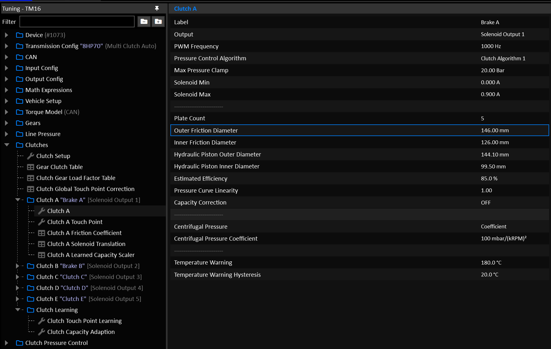
Clutch Geometry
Clutch geometry is taken into account in two directions:
- Calculating how much pressure to apply to hold a given torque.
- Calculating how much torque a given pressure can hold.
Plate Count
The number of friction plates in the clutch assembly. Aftermarket clutch kits often have increased plate counts, make sure to enter the correct number here.
Friction Diameters
The inner and outer diameters of the friction plate(s) should be entered accurately. Ideally these should be physically measured.
Hydraulic Piston Diameters
The hydraulic piston refers to the chamber that is filled with fluid in order to apply clamping force to the clutch. In the case of a fully open chamber without a shaft running through it (cylinder as opposed to a doughnut), an inner diameter of 0.0mm is valid.
Estimated Efficiency
Estimates the inefficiencies or mechanical losses involved in converting a given hydraulic pressure to a clamping torque capacity.
Typical Value: 85.0%
Pressure Curve Linearity
Bends the clutch’s Torque to Pressure translation into a non linear curve.
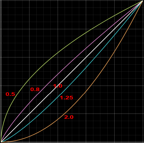
Typical Value: 1.00
Capacity Correction
Enables a table that allows the user to manipulate the final calculations.
In most cases this should NOT be used.
Typical Value: OFF
Clutch Friction Coefficient
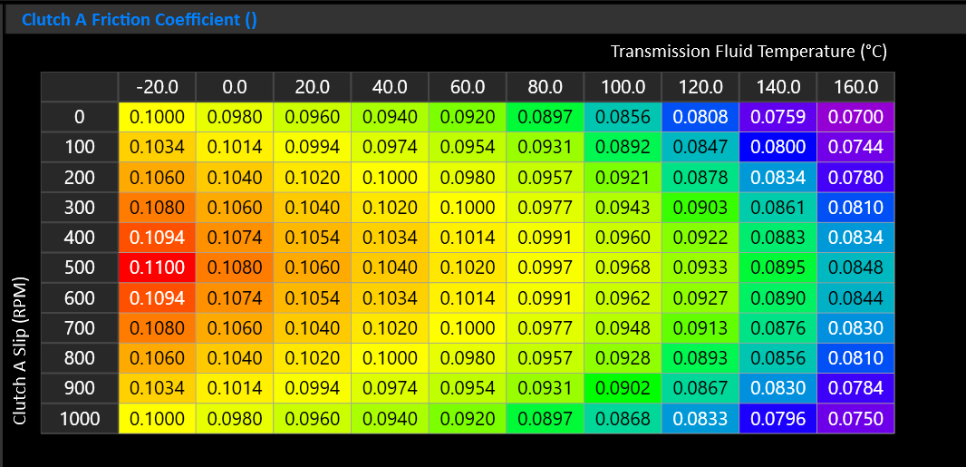
This table controls the frictional behavior of the clutch. Typically a wet clutch will have an increase in friction as it heats up with moderate slip, before falling back off as slip increases.
If you’re unsure, a generic table is provided that can be loaded in as a good starting point.
Centrifugal Pressure
Wet clutch drums spinning at speed generate centrifugal hydraulic pressure that acts on the piston independently of commanded pressure. At high drum speeds this can cause an offgoing clutch to partially engage even when you command only touch-point pressure.
On some transmissions dragging will be evident as a torque interruption or slip resistance during rev-matched downshifts. It may feel like the car is being pushed when the clutches should be fully slipping.
Select the mode used to calculate Clutch Centrifugal Pressure.
- Modelled = Clutch geometry based.
- Coefficient = Uses a coefficient that is independent of clutch geometry.
Modelled Centrifugal Pressure
When Clutch Centrifugal Pressure is in Modelled mode, the Clutch’s Centrifugal Pressure is calculated using the clutch geometry. Cancellation Efficiency represents how well the clutch resists the build up of centrifugal pressure.
- 0% = Full Modelled Centrifugal Pressure, maximum correction.
- 100% = No Modelled Centrifugal Pressure, no correction.
Centrifugal Pressure Coefficient
The coefficient compensates by subtracting from the total target pressure for the offgoing clutch.
- Start at 0 (disabled).
- Increase in steps of 20-30.
At 3000 RPM, each step of 10 removes appox. 0.09 bar of commanded pressure.
Typical Value: 0 or 100 - 200
Clutch Gear Load Factor
Not required for DCT Transmissions
Tip
This table is considered “Set & Forget”. It should be setup early on and left, rather than used as a tuning table.
Multi-clutch automatic transmissions use multiple clutches and brakes to create each gear. These elements do not share torque equally. Depending on the gear ratio and planetary gearset layout, one element may carry much more reaction torque than another. Each clutch will often have a different input torque applied to it depending on the combinations of clutches and gears also applied for a particular gear.
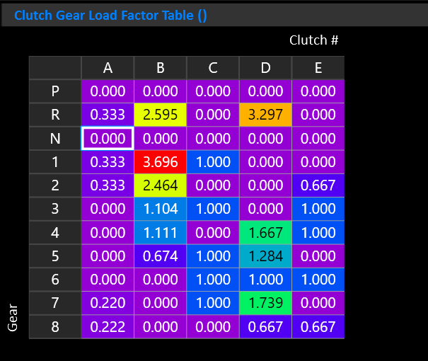
The Clutch Gear Load Factor table accounts for this internal torque multiplication on a per gear and per clutch basis.
This allows the TCM to estimate how much torque capacity each applied element needs in each gear.
Important
- X Axis must be “Clutch #”
- Y Axis must be “Gear”
- Z Axis is not used
The values in this table are not gear ratios or pressure multipliers. They are torque-capacity multipliers used before the torque-to-pressure calculation.
The resultant input torque for each clutch is shown by the “Clutch N Input Torque” runtime.
Important Notes:
- Load Factors can be calculated from the transmissions gear set.
- Only elements that are applied in a gear should have non-zero values. Elements that are released in that gear should be set to zero.
- Increasing a value will increase the calculated torque capacity requirement for that element in that gear, resulting in higher commanded pressure.
- Decreasing a value will reduce the calculated pressure requirement.
- If the value is too low, the clutch or brake may slip under load.
- If the value is too high, the shift or gear engagement may become harsh, inefficient, or create unnecessary clutch stress.
- It’s recommended to set each Clutch’s Learned Capacity Scaler Table Y axis of “Gear”. This allows the clutches to learn on a per-gear basis.
Clutch Pressure Control
The TCM needs to apply pressure to the clutch(s) in two main scenarios:
- In Gear (Active Clutch Pressure)
- During a shift
Other sub systems such as Takeup can takeover the clutch pressure control. They’re documented separately.
Active Clutch Pressure
The Active Clutch Pressure refers to the pressure applied to a clutch that is transmitting normal in-gear torque. The primary influencing factor on Active Clutch Pressure is Torque.
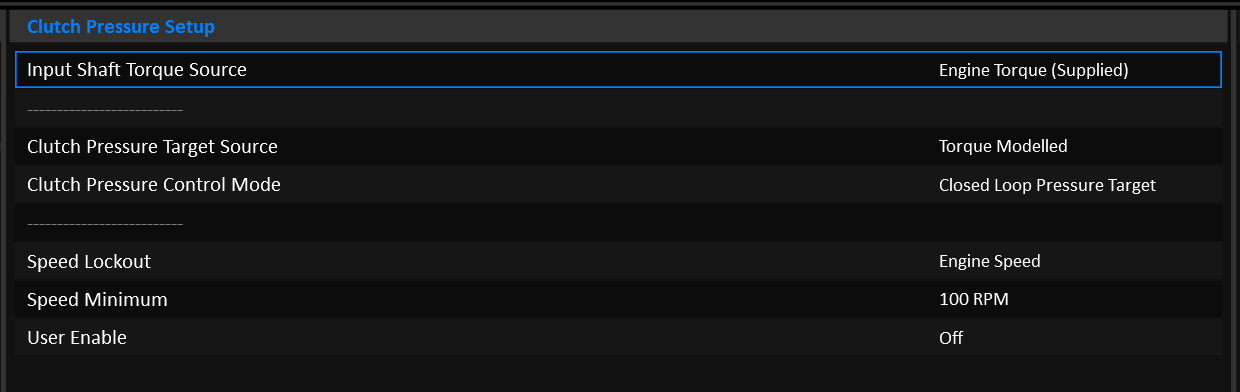
Input Shaft Torque Source
Torque based clutch pressure uses the Input Shaft Torque runtime for it’s calculations. The source of Input Shaft Torque can come from:
- Engine Torque (Supplied)
- Engine Torque (Available)
- Engine Torque (Supplied & Inertia Corrected)
Most setups would use
Engine Torque (Supplied).
Clutch Pressure Target Source
The pressure applied can be calculated in a number of ways:
- Torque Modelled
- User Defined
- Line Pressure Controlled
Tip
DCT Transmissions should almost always use Torque Modelled mode.
Target Source: Torque Modelled
---
title: Torque Modelled Clutch Pressure
---
graph LR;
  Prs(Clutch Pressure) -->|Bar| PID(PID)
  Tq(Input Shaft Torque) -->|Nm| TqCap{Sum: Required Torque Capacity}
  Clamp(Clamping Torque Margin) -->|Nm| TqCap
  TqCap -->|Nm| Geo(Clutch Model)
  Geo -->|Bar| Src{<strong>Clutch Pressure Target Source</strong>}
  Src -->|Bar| Sol(Solenoid Translation)
  Sol -->|Amps| PID
  PID --> |Amps| Curr[Solenoid Current]
  Src -->|Bar| PID
It is absolutely critical that the engine torque data is accurate.
Clutch Pressure is calculated using the Clutch’s geometry model. The pressure that comes out of the clutch model is intended to be the minimum pressure required to hold a given input torque, no more. The user can (and should) apply a Clamping Torque Margin on top of the Input Shaft Torque so that the clutch is commanded to hold slightly more torque and apply a slightly higher pressure as a result.
PID Control can be enabled if a Clutch Pressure Sensor is available.
For detailed information on how to setup the clutch model, see the Clutch Model documentation.
Target Source: User Defined
---
title: User Defined Clutch Pressure
---
graph LR;
  Prs(Clutch Pressure) -->|Bar| PID(PID)
  Tgt(Active Clutch Pressure Target) -->|Bar| TgtFnl{Target * Correction \+ Offset}
  Corr(Active Clutch Pressure Correction) -->|%| TgtFnl
  Offs(Active Clutch Pressure Offset) -->|Bar| TgtFnl
  TgtFnl -->|Bar| Src{<strong>Clutch Pressure Target Source</strong>}
  Src -->|Bar| Sol(Solenoid Translation)
  Sol -->|Amps| PID
  PID --> |Amps| Curr[Solenoid Current]
  Src -->|Bar| PID
In user defined mode, the Clutch Pressure Target simply comes from a Table. Optionally a Correction and Offset can be applied.
PID Control can be enabled if a Clutch Pressure Sensor is available.
Target Source: Line Pressure Controlled
---
title: Line Pressure Controlled Clutch Pressure
---
graph LR;
  LnPrs(Line Pressure) -->|Bar| Src{<strong>Clutch Pressure Target Source</strong>}

  PrsMax(Clutch Model: Max Pressure) --> |Bar| Sol(Solenoid Translation)
  Sol --> |Amps| Curr[Solenoid Current]
This mode is a special case for transmissions that simply expose all active clutches to full line pressure when in gear. This is the case for transmissions such as the ZF 8HP.
The Pressure Target and Solenoid Current are completely decoupled in this mode:
- The clutch solenoid is held at the current that achieves the maximum pressure (as configured in the Clutch Setup) according to it’s Solenoid Translation table.
- Line Pressure is copied into the
Active Clutch Pressureand Clutch # Pressure Target runtimes simply to give them something useful to display.
PID control cannot be used.
Shift Pressures
During a shift, the clutch pressure is fully modelled. No user defined pressure mode is available. The process of controlling a shift with user defined tables would put an enormous tuning burden on the end user that would require a lot of time to configure. The user can still tune a lot about how the shift feels, they just don’t have to worry about the actual pressures involved.
Calculating the pressure during a shift is very similar to when in gear, but the input torque will depend on weather the clutch is oncoming or offgoing, and the phase of the shift.
---
title: Torque Modelled Clutch Pressure
---
graph LR;
  Prs(Clutch Pressure) -->|Bar| PrsPid(Pressure PID)
  Tq(Input Shaft Torque) -->|Nm| ShtTq{Clutch/Phase/Slip Torque Manipulation}
  EngIn(Engine Inertia) -->|kg⋅m²| ShtTq
  EngSpdDt(Engine Speed Delta) -->|RPM/s| ShtTq
  GearSpd(Oncoming/Offgoing Gear Speeds) -->|RPM| ShtTq
  SlpTgt(Slip Target) -->|RPM| ShtTq
  Slip(Clutch Slip) -->|RPM| ShtTq
  ShTime(Shift Time Targets) -->|ms| ShtTq

  SlpTgt(Slip Target) -->|RPM| ShtPid
  Slip(Clutch Slip) -->|RPM| ShtPid
  ShtTq -->|Nm| ShtPid(Shift PID)
  ShtPid -->|Nm| TqFinal(Shift Torque)
  TqFinal -->|Nm| Geo(Clutch Model)
  PrsRate(Clutch Pressure Rate Limits) -->|Bar/s| Src
  Geo -->|Bar| Src{<strong>Clutch Pressure Target</strong>}
  Src -->|Bar| Sol(Solenoid Translation)
  Sol -->|Amps| PrsPid
  PrsPid --> |Amps| Curr[Solenoid Current]
  Src -->|Bar| PrsPid
It is absolutely critical that the engine torque data is accurate.
For detailed information on the shift phases, see the Multi-Clutch Shifting documentation.
For detailed information on how to setup the clutch model, see the Clutch Model documentation.
Clutch Touch Points
One of the most important things to setup on a new installation is the clutch touch points.
The touch point refers to the amount of pressure applied to the clutch before any meaningful torque capacity is applied.
- Below the touch point, the clutch is fully slipping.
- Above the touch point, the clutch is starting to hold torque.
The clutch’s torque capacity starts at the touch point. It’s effective pressure is it’s total pressure less it’s touch point. For example:
The user MUST find the touch point of each clutch. Failing to do so will result in poor drivability and shifting.
Touch Point Tuning
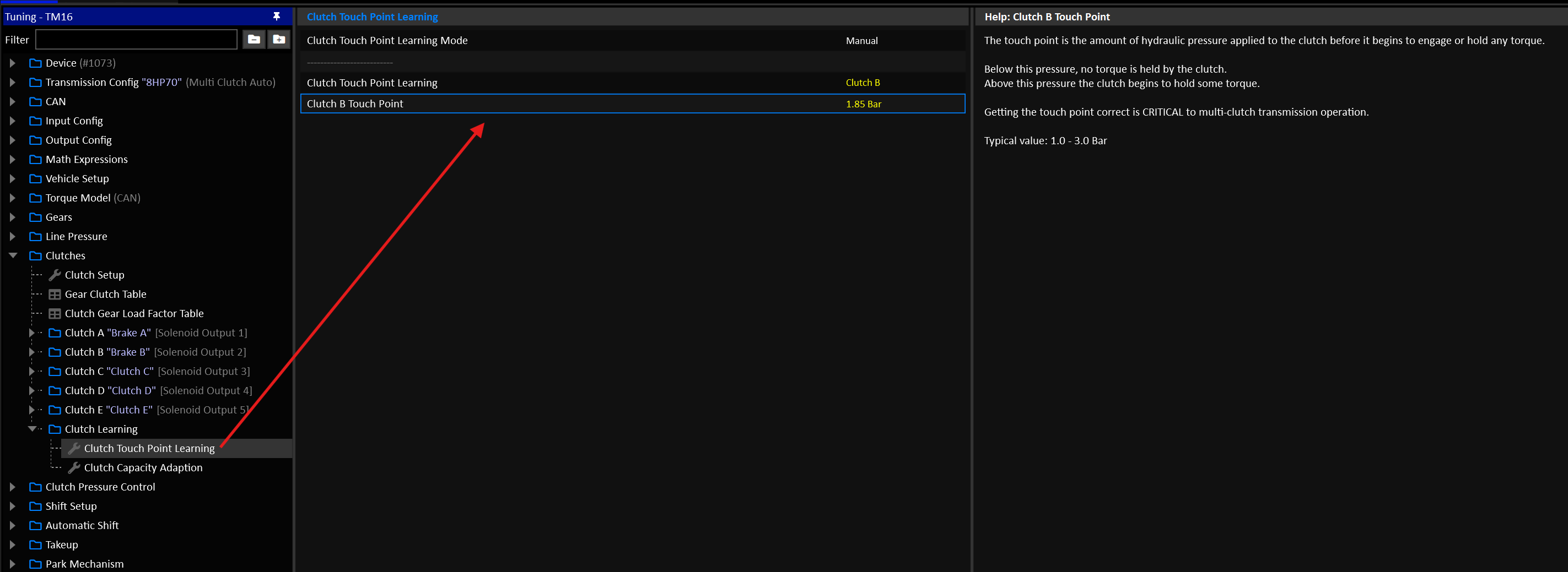
To find the touch points, the following condition must be met:
- Transmission Fluid Temperature: 60-90°C
- Gear: Neutral
- Brake: ON
- Input Shaft Speed: 500-2000 RPM
- Output Shaft Speed: 0 RPM
Automated Touch Point Learning
You can put the TCM into automated learning mode for a given clutch. For this system to work, the engine idle speed needs to be very stable. On engines where the idle speed is rough (large camshafts etc), it’s likely better to do manually.
Set the clutch to be tested and the TCM will engage all relevant surrounding clutches that would result in a driving gear using the clutch in question. It will then slowly ramp the clutch pressure up and look for a dip in Input Shaft Speed. This process will be repeated 5 times and the result of those tests will be averaged to find the final touch point.
The test will exit if the entry conditions are no longer met, Eg: The user releases the brake.
If the automated test errors out, an erroneous value may be applied to the clutch’s touch point and the test should be run again.
Manual Touch Point Learning
- Set the clutch to be tested and the TCM will engage all relevant surrounding clutches that would result in a driving gear using the clutch in question.
- Slowly increase the Touch Point Setting and watch for the moment where the clutch starts to drag on the input shaft.
- The actual touch point will be a little before this, where any more pressure results in noticeable drag.
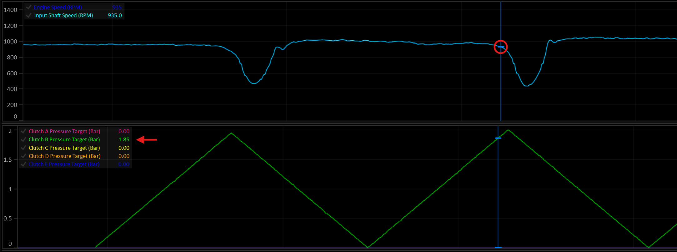
In this example, as Clutch B reaches ~1.85 Bar, the Input Shaft Speed begins to noticeably dip as drag is applied to the input shaft. The actual touch point, before the clutch begins to drag on the input shaft, would be slightly before that at about 1.75 Bar.
Touch Point Correction
A correction scaler can be applied on either a global or per-clutch level. If you find that at varying fluid temperatures the touch points need adjustment, these corrections can address that.
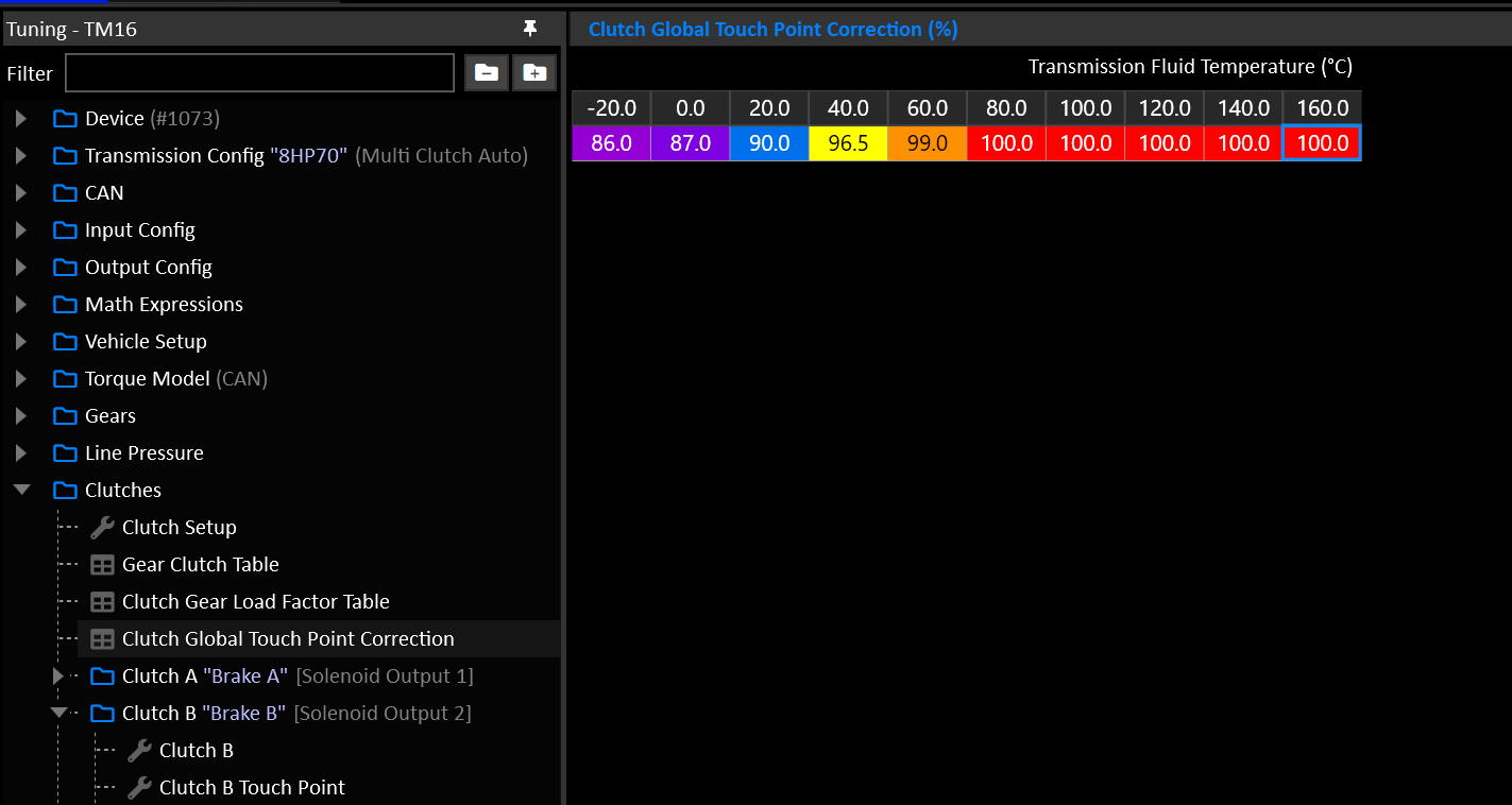
Here, at 20°C a nominal Touch Point of 1.75 Bar would become 1.57 Bar.
Data Logging
The TCM has a built-in data logger that records selected channels to eMMC memory.
| Logging Specs | |
|---|---|
| Max Capacity | 8GB |
| Max Channels | 500 |
| Max Frequency | 1000 Hz |
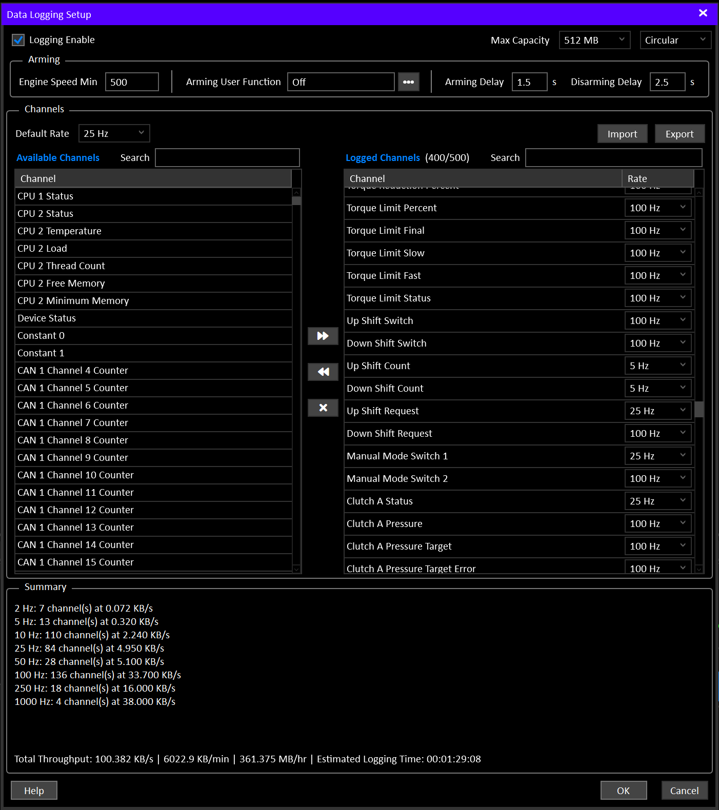
Logging Enable must be ON in Data Logging Setup, and at least one channel must be selected. With Logging Enable OFF the logger is completely inactive and ignores all arming conditions.
Sessions
Each time the logger arms, a new recording session starts. Everything recorded until it disarms belongs to that session.
A single download can contain many sessions (e.g. several on/off cycles across a track day). When the log is downloaded, all sessions are joined together in time order, with a marker at each session boundary so they can still be told apart on a chart.
Channels
A maximum of 500 channels can be selected for logging.
Each channel can be recorded at any of the following frequencies:
- 1 Hz
- 2 Hz
- 5 Hz
- 10 Hz
- 25 Hz
- 50 Hz
- 100 Hz
- 250 Hz
- 500 Hz
- 1000 Hz
Each frequency option can have a maximum of 255 channels assigned.
For Example: You can choose 255 channels at 100 Hz and 100 Channels at 50Hz, but you cannot choose 355 channels at 100 Hz.
Channels are moved from Available Channels into Logged Channels, where each one is assigned a rate. Default Rate sets the rate newly added channels start at, and the rate of several channels can be changed at once from the right-click menu. The setup screen will not allow either channel limit to be exceeded.
A channel list (channels and rates) can be saved to a file and reloaded with Export and Import. This is useful for keeping a few standard setups (e.g. “track day”, “dyno session”) and switching between them, or between vehicles.
Tip
To maximize memory usage, only log channels as fast as necessary.
- Slow moving signals like temperature’s only need to be 5-25 Hz
- Fast moving signals like clutch pressure benefit from being faster (100-250 Hz)
Capacity
The maximum capacity of the logging memory is a little under 8GB. Some space is reserved for config storage and other system functions. The memory capacity used by the Data Logging system can be set from 128MB to 8GB. Downloading a log from a fully filled 8GB capacity will take a very long time (over an hour), so it can be useful to limit the maximum logging capacity to make it more practical.
One-Shot / Circular Mode
Data logging can be used in two distinct modes:
- One-Shot: Once full, logging stops. No new data is recorded until the memory is erased.
- Circular: Once full, the oldest data will be overwritten with new data.
Circular mode is extremely useful for set and forget logging. You can enable it and leave it running. In the event that something happens that you want to review, the most recent data will always be available.
Limiting the total capacity in circular mode makes periodic log downloads more manageable.
Example:
A typical “full coverage” logging set might have 400 channels in it. Setting the capacity to 512MB might result in about 1.5 hours of total logging time, which will only take a couple of minutes to download in the event that you want to review it.
Partial Sessions
In circular mode, when the logging capacity is reached and a logging session is still recording, writing wraps back to the start of the memory, overwriting the oldest session data. A session that gets overwritten will loose it’s channel information first, followed by it’s oldest data. If the user has not changed the logging channel selection or frequencies, the partially overwritten data can still be decoded as it’s channel layout will match the newer sessions. If the user changes the channel or frequency layout, the entire old session will be lost.
Note
Switching from Circular back to One-Shot after the log has wrapped will erase the log. Once data has been overwritten in a loop, there is no single continuous recording left to keep.
Estimated Logging Time
Data Logging Setup shows a live Estimated Logging Time for the selected channels and rates. This is the figure to check before a recording session.
As a guide to the scale involved, the table below uses 10 channels at a single rate, assuming a typical mix of channel sizes:
| Rate | Data rate | Fills 1 GB in | Fills 8 GB in |
|---|---|---|---|
| 1 Hz | ~40 B/s | ~310 days | ~6.8 years |
| 2 Hz | ~80 B/s | ~155 days | ~3.4 years |
| 5 Hz | ~200 B/s | ~62 days | ~1.4 years |
| 10 Hz | ~400 B/s | ~31 days | ~249 days |
| 25 Hz | ~1.0 KB/s | ~12.4 days | ~99 days |
| 50 Hz | ~2.0 KB/s | ~6.2 days | ~50 days |
| 100 Hz | ~4.0 KB/s | ~3.1 days | ~25 days |
| 250 Hz | ~10 KB/s | ~30 hours | ~10 days |
| 500 Hz | ~20 KB/s | ~15 hours | ~5 days |
| 1000 Hz | ~40 KB/s | ~7.5 hours | ~2.5 days |
Logging 10 channels at every rate at once (100 channels) comes to roughly 76 KB/s, which fills 1 GB in around 4 hours and 8 GB in around 31 hours. Choosing a sensible rate for each channel is the biggest factor in how long a recording lasts.
Arming / Disarming
The logger can be armed in a number of ways:
| Condition | Description |
|---|---|
| Logging Enable Switch | When ON, the logger will run as long as Engine Speed Min is exceeded. |
| Arming User Function | The logger will run when the selected User Function is ON and Engine Speed Min is exceeded. |
Info
If Engine Speed Min is greater than zero, it will lockout the logger until it’s exceeded.
If the Logging Enable Switch is OFF AND Arming User Function is OFF, the logger will enable when Engine Speed Min is exceeded. This is the absolute minimum required arming condition.
Arming / Disarming Delays
- Arming Delay: Delays arming until the arming conditions have been true for the delay time (0-25 seconds).
- Disarming Delay: Delays disarming until the arming conditions have false for the delay time (0-25 seconds).
Downloading
Logging is paused while a log is downloaded, and resumes automatically afterwards if the logger is still armed. Logging and downloading cannot happen at the same time.
Before downloading, the number of sessions recorded since the last erase and how full the memory is are shown. If nothing has been recorded since the last erase, Download and Erase are unavailable.
Downloads run over Ethernet at roughly 1.5 MB/s. As a guide, a full 1 GB log takes around 12 minutes to download, and a full 8 GB log around an hour and a half.
Once downloaded, a Log Details screen is shown before the log file is saved. Vehicle and Transmission are filled in from the Device Label and Transmission Label settings, and the remaining details (driver, venue, weather, notes, etc.) can be added.
Erasing
Erasing clears the entire log. Logging is paused and resumed automatically around the erase, and confirmation is requested if the log contains data.
Log Markers
When configured, the Log Marker Switch input can be used to mark moments in time in the logged data.
On the rising edge of the switch, the next single batch of log data will be marked. This mark will show up in the plotted data as a dotted blue line.
Power Loss Behavior
The logging system commits data from RAM to permanent memory approximately once per second. The TCM should be wired to be in control of it’s own power supply. This allows it to shutdown the data logging system and ensure that any pending data sitting in RAM is committed before powering itself down.
In the event of an unexpected power loss, any data still in RAM will be lost. This is typically ~1 second worth of data.
Drive Modes
Drive Modes refer to the main transmission states such as Park, Reverse, Neutral, and Drive (Auto, Sport, Manual). Selection of the desired drive mode can be achieved a variety of ways including:
- CAN bus shifter (preset or custom)
- Analog shifter position
- Digital shifter position matrix
- Switches or buttons
- Up Shift & Down Shift switches
- Combinations of the above
Drive Mode Input Priorities
Drive mode input sources have fixed priorities. This allows them to be used in conjunction with one-another with predictable results. Inputs with higher priority will override inputs with lower priority.
| Priority | Input Source |
|---|---|
| 1 (Highest) | Park Request Switch |
| 2 | Neutral Request Switch |
| 3 | Shifter Position (Park / Reverse / Neutral) |
| 4 | Reverse Request Switch |
| 5 | Manual Switch |
| 6 | Sport Switch |
| 7 | Drive Switch |
| 8 | Shifter Position (Drive / Sport / Manual) |
| 9 | Up Shift Switch |
| 10 (Lowest) | Down Shift Switch |
Example: If the shifter is in the Neutral position, but the Park Request Switch is enabled and in the active (ON) state, the transmission will remain in Park until the Park Request Switch becomes inactive (OFF) because the Park Switch has higher priority than the Shifter Position input.
Manual Override
Manual Override puts the TCM into Manual while Drive or Sport is selected, without the driver having to select Manual. It is applied after the input priorities above, and can come from the Manual Override Switch or from the Up Shift & Down Shift switches.
While the Manual Switch has selected Manual, the Manual Override inputs have no effect.
Manual Override Switch
While the Manual Override Switch is ON, selecting Drive or Sport gives Manual instead. Turning the switch OFF returns the TCM to Drive or Sport.
This works however Drive or Sport is selected (shifter, Drive or Sport Switch, or holding Up Shift from Neutral), and whether the switch is turned ON before or after Drive or Sport is selected.
Example: The
Manual Override Switchis already ON when the TCM starts up. Selecting Drive from Neutral goes straight to Manual. Turning the switch OFF then changes to Drive.
Selecting Park, Reverse or Neutral ends the override. If the switch is still ON when Drive or Sport is selected again, the TCM goes back to Manual.
Up / Down Shift Switches
Set Up / Down Shift Switch Behaviour (Automatic Shift > Auto Shift Setup) to Manual Override to have an Up Shift or Down Shift press in Drive or Sport change to Manual. The press also requests the shift.
The TCM returns to Drive or Sport when any of the following happens:
- Manual Override Timeout: No Up Shift or Down Shift press has been made for this time. Each press restarts the timer. Set to 0 to stay in Manual until cancelled.
- The
Manual Switchis pressed. - Park, Reverse or Neutral is selected.
If the Manual Override Switch is also ON, the TCM stays in Manual until that switch is turned OFF.
Cancelling with the Manual Switch
Pressing the Manual Switch only cancels the override when the switch is connected to a TCM input. It doesn’t work when the Manual Switch comes from CAN or a script.
Engine Torque
Important
Accurate engine torque modelling is critical for transmission performance.
Engine Inertia
Engine inertia is used to calculate the clutch torque required to sync the engine speed during a shift. It also informs the rev-match torque calculation.
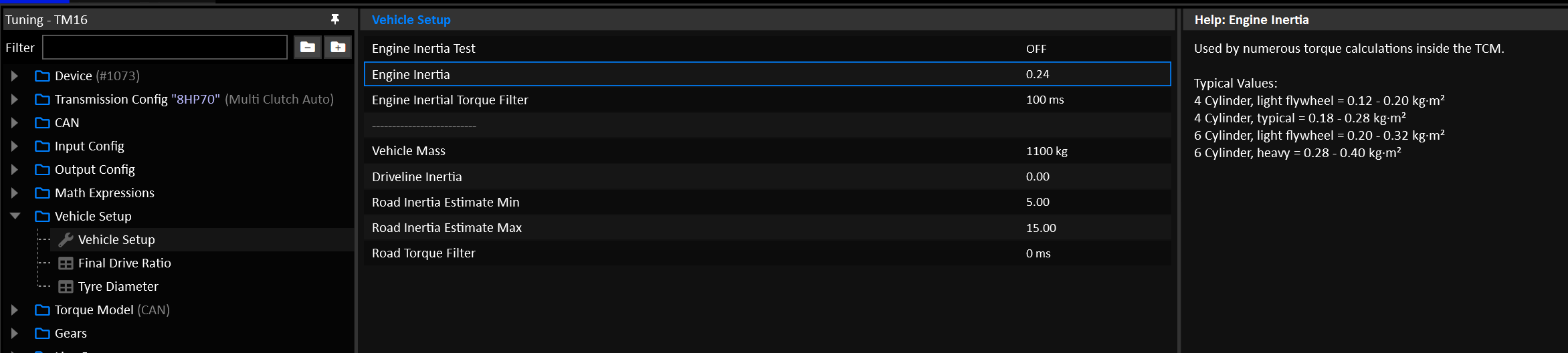
| Engine / configuration | Typical Inertia (kg·m²) |
|---|---|
| Small 4-cyl light flywheel | 0.12 – 0.20 |
| Typical 4-cyl production | 0.18 – 0.28 |
| Performance 6-cyl (light flywheel) | 0.20 – 0.32 |
| Heavier 6-cyl / street flywheel | 0.28 – 0.40 |
| Big heavy flywheel / truck | 0.40 – 0.70+ |
Launch Control
Warning
Launch Control is a motorsport orientated function can lead to transmission and/or other driveline component damage if not used correctly.
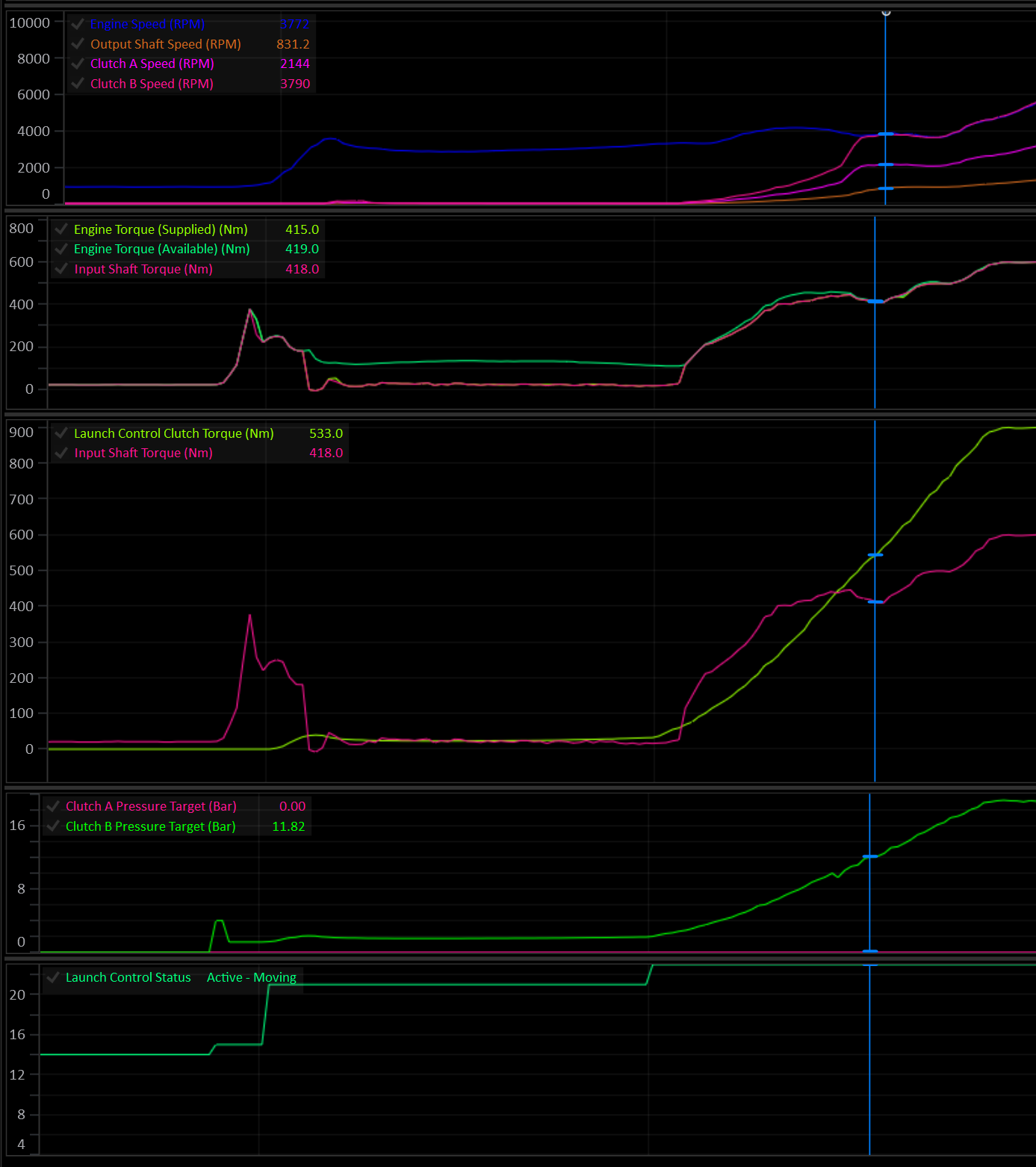
Overview
Launch Control can be configured in a variety of way depending on the desired control outcome.
Launch control can be configured to:
- Control clutch torque and clutch torque rate.
- Generate an Engine Speed Target to be sent to the engine.
- Generate a torque limit to to be sent to the engine.
There are 5 main states/phases the Launch system can be in:
| State | Meaning |
|---|---|
| Disarmed | Off, or arming conditions not currently met. |
| Armed | Arming conditions met, waiting for launch lockouts to clear. |
| Static | Car stationary, launch active. Clutch is typically held open/slipping to a torque target. |
| Preload | (Optional) Clutch is pre-loaded to a torque target for a fixed dwell time before the final dump. |
| Moving | Clutch torque is actively controlled through the launch. Ends when a disarm condition is met. |
Set Enable to ON in Launch Control Setup to turn Launch Control on. While disabled, it has no effect on clutch pressure, engine speed target or torque limit.
Clutch Control
The primary function of Launch Control is to override the clutch pressure by generating a clutch torque request.
Clutch Control is enabled in Launch Control Setup.
Launch Control never engages a clutch that isn’t already part of the currently selected gear. It can only override the pressure target of a clutch the TCM has already activated for that gear. It cannot bring in an extra clutch on its own.
Launch Control Clutch Select
Care should be taken to ensure the Launch Control Clutch Select table is set up correctly. In most case the table will be identical to the Takeup Clutch Select table.
Important
The Clutch Select table’s X axis MUST be Clutch #.
The table is re-evaluated each time the system re-arms into the Static phase. This allows the table’s Y axis to be another channel such as Gear.
When Clutch Control is disabled, Launch Control does not touch clutch pressure at all — only the engine RPM target / torque limit outputs (if enabled) are active.
Arming & Disarming
Arming
The system arms when every configured arming condition is simultaneously true. Each condition is independently optional (Eg: 0 = OFF). Enable only the conditions relevant to your application.
At least one condition must be configured, or the system will report “Disarmed - No Arming Config” and never arm.
| Condition | Enable via | Threshold |
|---|---|---|
| Launch Switch | Launch Arming Switch = ON | Launch Arming Switch = ON |
| Brake Switch | Brake Switch Arming = ON | Brake Switch 1 = ON |
| Brake Pressure | Arming Brake Pressure Minimum > 0 | Brake Pressure Front > Threshold |
| Transbrake Switch | Transbrake Switch Arming = ON | Transbrake Switch= ON |
| User Function | Arming User Function ≠ Off | User Function # Status = ON |
Static → Moving
Releasing any configured arming condition while in Static or Preload is what triggers the transition into Preload/Moving.
Lockouts (Armed → Static)
Once armed, the system waits for all configured lockouts to clear before entering the Static phase.
At least one lockout must be configured, or the system will report “Lockout - No Lockout Config” and will not enter Static.
| Lockout | Enable via | Condition to clear |
|---|---|---|
| Gear | Always active | Gear ≥ 1st |
| Clutch By Wire | Always active | CBW must not be active |
| Pedal/throttle position | Static Lockout Pedal/Throttle Position > 0 | Pedal Position* ≥ Threshold |
| Output Shaft Speed | Static Lockout Output Shaft Speed > 0 | Output Shaft Speed < Threshold |
| Drive Speed | Static Lockout Drive Speed > 0 | Drive Speed < Threshold |
| Engine speed | Static Lockout Engine Speed > 0 | Engine Speed > Threshold |
| User Function | Static Lockout User Function ≠ Off | User Function # Status = ON |
* If
Pedal Positioninput is not configured,Throttle Positionis used.
Disarming (Static / Preload / Moving → Disarmed)
While active, the system aborts back to Disarmed immediately if:
- The TCM begins a shift.
- The gear selector leaves Drive/Manual (enters Park/Neutral/Reverse)
- Any one of the following (each optional) stays true for longer than the
Disarming Time(ms):
| Disarm condition | Enable via | Trips when |
|---|---|---|
| Pedal/Throttle Position | Disarming Pedal/Throttle Position > 0 | Pedal Position* < Threshold |
| Output Shaft Speed | Disarming Output Shaft Speed > 0 | Output Shaft Speed > Threshold |
| Drive Speed | Disarming Drive Speed > 0 | Drive Speed > Threshold |
| Engine Speed | Disarming Engine Speed > 0 | Engine Speed < Threshold |
| Clutch Slip | Disarming Clutch Slip > -1000 | Clutch Slip < Threshold (clutch locked) |
* If
Pedal Positioninput is not configured,Throttle Positionis used.
If no disarming condition is configured, the system disarms immediately (nothing is holding it active).
Active Launch Phases
Static
In the Static phase the car is stationary with the engine is held at the desired launch RPM (this is to be controlled by the engine ECU). The TCM can generate a torque limit and/or Engine Speed Target to be issued to the engine via CAN.
Static Clutch Torque: Typically the clutch is either fully open or a small amount of torque is applied for the engine to load up against.
Caution
Applying clutch torque during static phase will lead to very high clutch temperatures and should be treated with caution.
Preload (optional)
Enabled when Preload Stage = ON in Launch Control Setup.
Preload is a dwell phase between Static and Moving where the clutch can be held at a preload torque target for a calibrated time, before the final dump.
It can be triggered in three ways:
| Trigger | Enable via | Behaviour |
|---|---|---|
| Auto | Preload Stage = ON, Preload User Enable = OFF, Preload Switch = OFF | Entered automatically the instant the arming condition is released. |
| Preload Switch | Preload Switch = ON | Entered as soon as Launch Preload Switch = ON. Can be requested before the arming condition is released, to preload ahead of the Moving phase. |
| Preload User Enable | Preload User Enable ≠ OFF | Entered as soon as User Function # Status = ON. Can be requested before the arming condition is released, to preload ahead of the Moving phase. |
Preload → Moving
- Preload will exit to Moving when
Launch Control Preload Timetable value expires, orMax Preload Timeexpires. - If Preload was entered manually (User Function or Preload Switch) rather than automatically, releasing the arming condition while still in Preload will cut it short and transition immediately to Moving.
Preload Clutch Torque: Typically, a small amount of torque is applied for the engine to load up against. The clutch torque rate is relatively slow so the engine doesn’t suddenly get dragged down.
Example:
- The driver arms launch with the
Launch Switchand enters Static. - A generous but not excessive time is entered into the Preload Time table (and Max Preload Time).
- Moments before launching the
Preload Switchis pressed and the system enters Preload. - Clutch pressure is ramped up & engine torque increases.
- Before the
Launch Preload Timeexpires, theLaunch Switchis released at the exact moment the driver wishes to launch. - The system then enters the Moving phase and ramps the clutch up to full lock torque.
In this scenario, the clutch can be loaded before launching, clutch temperature is minimised, and the driver is still in full control of the moment of launch.
Moving
During the moving phase, clutch torque is ramped up to full lock torque at a controlled rate.
Moving Clutch Torque: The final clutch torque should result in the clutch being fully locked. In a properly modelled system, the clutch will lock when it’s applied torque meets or exceeds the Input Shaft Torque. In a multi-clutch transmission with gear clutch load factors other than 1.0, this may vary and should be considered.
Moving Clutch Torque Rate: Clutch torque should be ramped in fast enough to minimise slip and engine flaring, while not dragging the engine speed down.
Tip
Most of the fine tuning time will be spent dialing in a suitable Moving Clutch Torque Rate.
Per-Phase Calibration Tables
Each of Static / Preload / Moving phases has its own set of tables. Torque Limits are enabled per-phase.
| Output | Enable via (per phase) | Table(s) |
|---|---|---|
| Engine Speed Target | Engine Speed Target Tables = ON (applies to all 3 phases) | Static/Preload/Moving Engine Speed Target |
| Engine Torque Limit | Static/Preload/Moving Torque Limit = ON | Static/Preload/Moving Torque Limit |
| Clutch Torque | Clutch Control = ON (applies to all 3 phases) | Static/Preload/Moving Clutch Torque |
| Clutch Torque Rate | Clutch Control = ON (applies to all 3 phases) | Static/Preload/Moving Clutch Torque Rate |
A phase’s torque limit is only applied while that phase is active. It’s released as soon as Launch Control moves to a phase without one, so a limit is never carried over from an earlier phase.
Runtime Channels
The following runtime channels are generated by the Launch control system:
- Launch Control Status (see Launch Control Status enumeration)
- Launch Control Engine Speed Target
- Launch Control Torque Limit
- Launch Control Clutch Torque
- Launch Control Static Time
- Launch Control Preload Time
- Launch Control Moving Time
Launch Control Status reports the current phase, or which arming condition or lockout is being waited on, which makes it the first channel to check when Launch Control won’t activate. The Static, Preload and Moving Time channels record how long each phase of the most recent launch took, for review after the run.
Interaction with Other Systems
Caution
Care should be taken to ensure other system lockouts are configured, in particular: Takeup.
- Transbrake: Transbrake clutches are unconditionally part of the active clutch set while held; Launch Control can overlay pressure on them like any other active clutch but never adds to the set itself.
- Takeup: If Takeup’s own
Launch Control Lockoutoption is set, Takeup control locks itself out whenever Launch Control is active (Static/Preload/Moving), so the two won’t fight over clutch pressure. - Clutch-By-Wire (CBW): An active CBW request blocks Launch Control from ever reaching Static (see lockout table above).
Multi-Clutch Shifting
Shifting on multi-clutch transmissions happens over 4 phase:
- Fill
- Torque Transfer
- Inertial Sync
- Lock
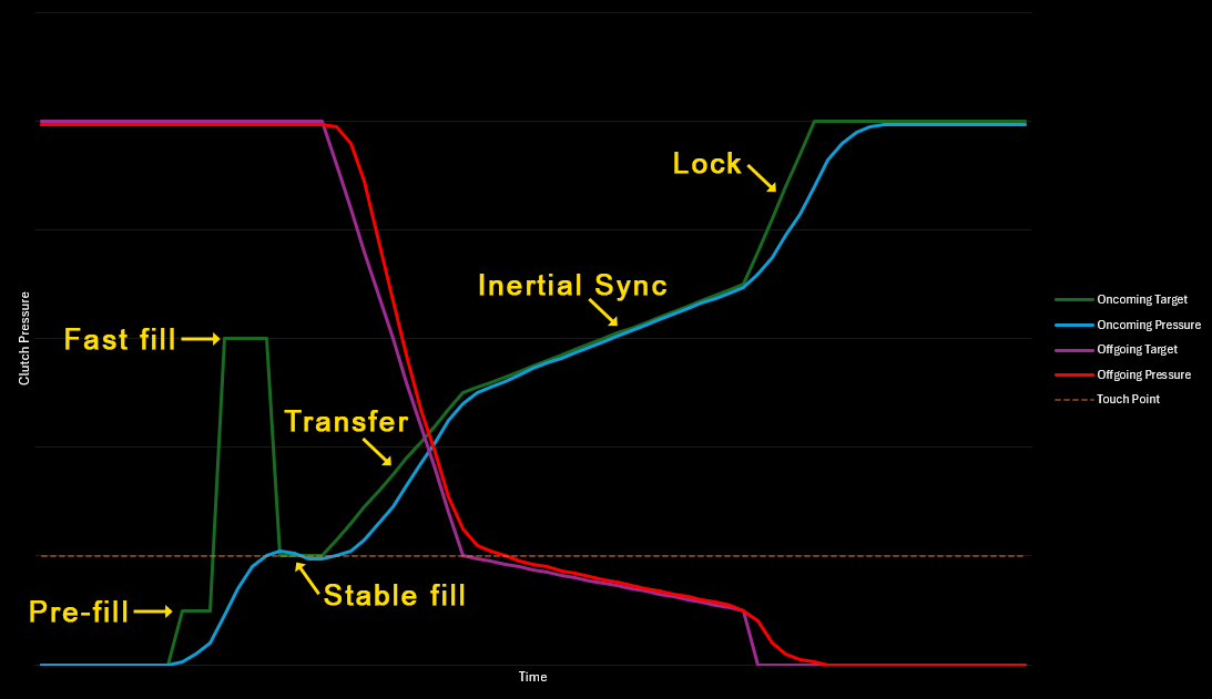
A simplified representation of the clutch pressures during the 4 shift phases.
The TCM will calculate all required clutch pressures based on supplied and available engine torque. As long as the clutch geometry is configured reasonably and the torque data from the engine is accurate, there’s very little tuning required.
It is absolutely critical that the engine torque data is accurate.
For detailed information on how the TCM converts torque to clutch pressure, see this section on Shift Pressures.
For detailed information on how to setup the clutch model, see the Clutch Model documentation.
Line Pressure
Caution
DO NOT try to tune the shifting on a multi-clutch transmission by manipulating the Line Pressure.
Line Pressure should be sufficient to supply all the pressure the clutches need during a shift, but the clutches should control their own pressures.
Clutch pressure can be considered a minimum value for the Line Pressure Target.
Some transmissions will require the Line Pressure to be set very high for the duration of a shift, giving maximum flow control to the clutch solenoids.
Depending on the transmission in question, setting the Line Pressure to “Downstream Pressure Offset” mode can simplify this process.
Fill Phase
Any clutch that is disengaged will have it’s pressure fully bled off. The job of the fill phase is simply to ensure that the oncoming clutch pressure chamber is filled with fluid so that it can operate as fast as possible once the shift actually starts.
Generally, the clutch pressure at the end of the Fill phase will be the clutch’s touch point pressure. The Fill phase is not intended to apply any meaningful clutch pressure.
Unlike the rest of the shift phases, the fill phase doesn’t use torque, it is purely pressure based.
The Fill phase is broken into 3 sub phases:
- Pre-Fill
- Fast Fill
- Stable Fill
The amount of time spent in each phase is limited by the Total Fill Time table and the phase order.
Example:
- Pre-fill = 20ms
- Fast fill = 40ms
- Total fill time = 100ms
Stable fill = 100 - (20 + 40) = 40ms
Setting a fill phase time to zero will result in that phase being skipped. It’s perfectly valid in many cases to skip the Pre-fill or the Fast Fill phase. It’s also common for high torque, high speed shifts to consist of only the Fast-Fill phase. In this case, the Pre-fill Time would be 0 and the Fast Fill Time would take up the entire Total Fill Time.
Regardless of the Pre-fill and Fast Fill times, the Fill phase will always exit once the Total Fill Time has elapsed.
Pre-Fill
The Pre-fill phase simply opens the clutch pressure solenoid at the very start of the shift. The specified pressure is absolute and disregards the touch point.
Pre-fill pressure does not usually exceed the touch point pressure.
Typical Pressure: 0.5 - 1.5 Bar Typical Time: 0-100ms
Setting the
Pre-Fill Timeto 0 will skip the Pre-fill phase.
Fast Fill
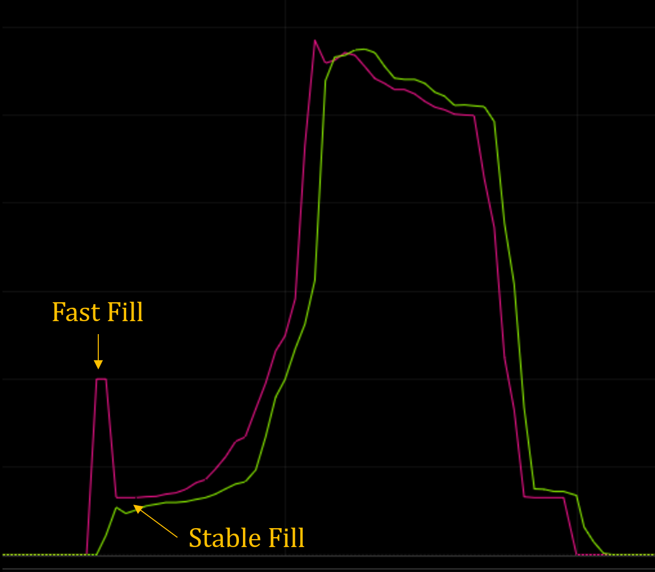
During Fast Fill, the clutch pressure solenoid is driven very high for a short period. The intention is to allow a fast in-rush of fluid to fill the clutch chamber as fast as possible.
Caution
A correctly configured combination of Fast Fill Pressure and Fast Fill Time should result in the actual pressure ramping up very quickly to, but never in excess of the touch point.
Typical Pressure: 3.0 - 5.0 Bar Typical Time: 20-50ms
Stable Fill
After the Pre-fill and Fast Fill phases are complete, any remaining Fill Time will be spent in the Stable Fill phase.
The pressure specified during Stable Fill is an offset of the clutch’s touch point pressure.
Example:
- Touch Point = 1.3 Bar.
- Stable Fill Pressure Offset = -0.1 Bar.
Stable Fill Pressure = 1.3 + -0.1 = 1.2 Bar.
Typical Pressure Offset: 0.0 Bar (Settle on the Touch Point)
Torque Transfer Phase
The Torque transfer phase begins the process of transferring supplied engine torque over to the oncoming clutch. In most cases, the oncoming clutch will still be fully slipping by the end of the phase, but it will be holding most of if not all the torque.
Up Shift & Overrun Down Shift
Torque is transferred to the oncoming clutch while the offgoing clutch is mostly released. By the end of the phase, the oncoming clutch will be carrying all the torque, but it will still be fully slipping at the offgoing gear speed. It’s the Inertial Sync phase’s job to reduce the slip to zero.
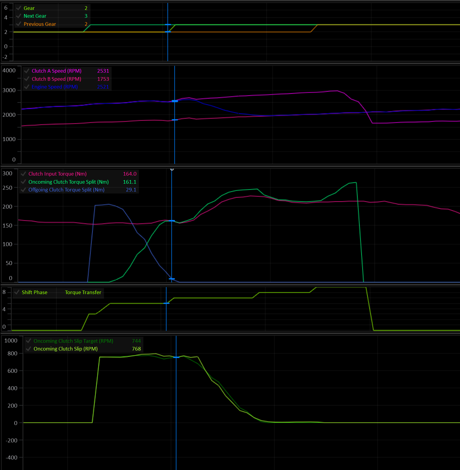
Note the engine speed is still matching Clutch A (offgoing) at the end of the transfer phase.
Driven Down Shift
During a driven down shift, the offgoing clutch’s torque capacity is reduced to deliberately introduce a controlled amount of slip that will bring the Input Shaft Speed up to the ongoing gear speed. As the clutch slip approaches zero, the oncoming clutch is ramped in to catch the input load, while the offgoing clutch is tapered out.
By the end of the Transfer phase the oncoming clutch slip should be near zero.
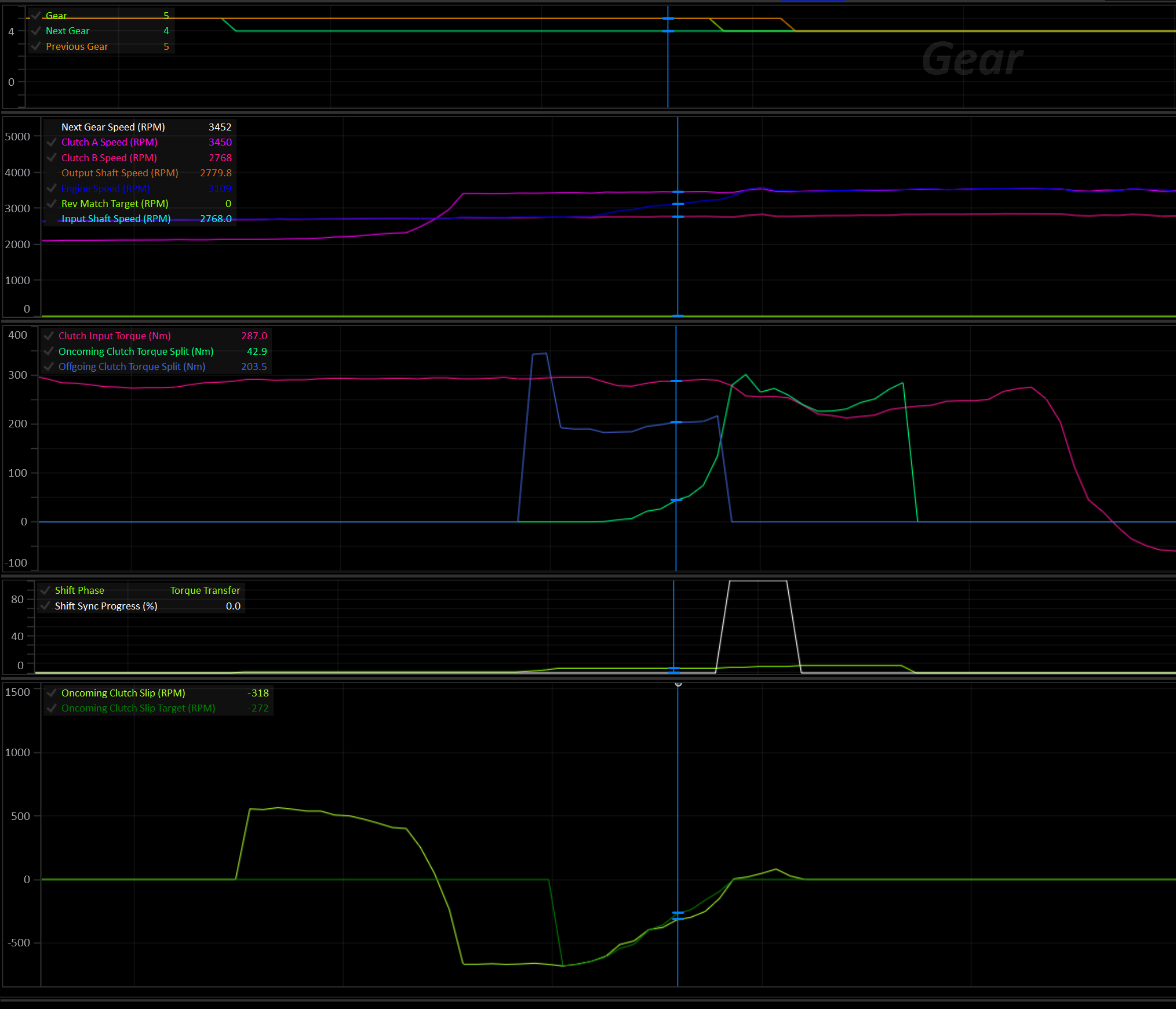
Driven Down Shift with ideal speed synchronization.
Down Shift Rev Match
During a rev match, both the offgoing and oncoming clutch are reduced to zero torque capacity. They will both settle on their touch points, allowing the engine to freely rev.
As the oncoming slip approaches zero, the oncoming clutch is ramped in to catch the input torque load.
Fast Fill During Transfer
When enabled, the Fast fill (and stable fill) phases are merged into the Torque Transfer phase. Both the transfer pressure and the fast/stable fill pressure are calculated at once. The highest of two is applied to the clutch.
This results in shorter shift times and faster pressure rates as the transfer pressure will simply take over as soon as it exceeds the fill pressure.
During fast shifts, the drop back to stable fill pressure can be effectively skipped.
Pre-fill always happens first if it’s time is non-zero.
Inertial Sync Phase
During this phase, clutch slip is reduced to near zero and the Input Shaft Speed is synced to the oncoming gear speed. Additional torque capacity is applied to the oncoming clutch to achieve this.
The engine’s inertia and torque is considered when calculating how much torque to apply to control the slip.
At high input torque, prolonged sync times will result in increased clutch heat and wear.
The main “Gear” runtime will change to the next gear at the start of the Inertial Sync phase.
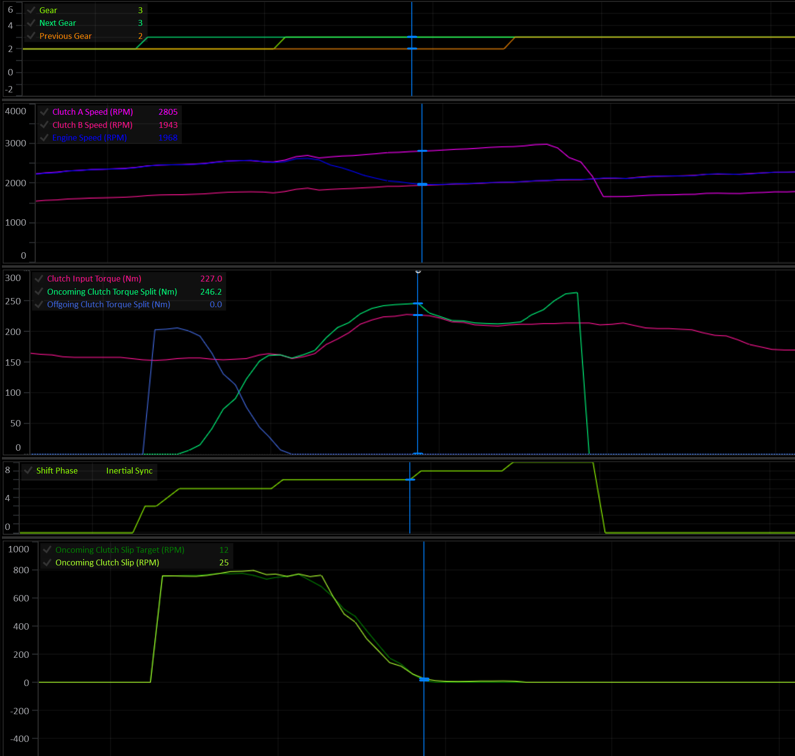
The Engine Speed is now matching Clutch B (oncoming) at the end of the Inertial Sync phase.
Torque Reductions
Any torque reduction that is enabled by the user is applied now to aid in syncing the Input Shaft Speed. Using torque reductions mean less clutch capacity is needed to achieve synchronization.
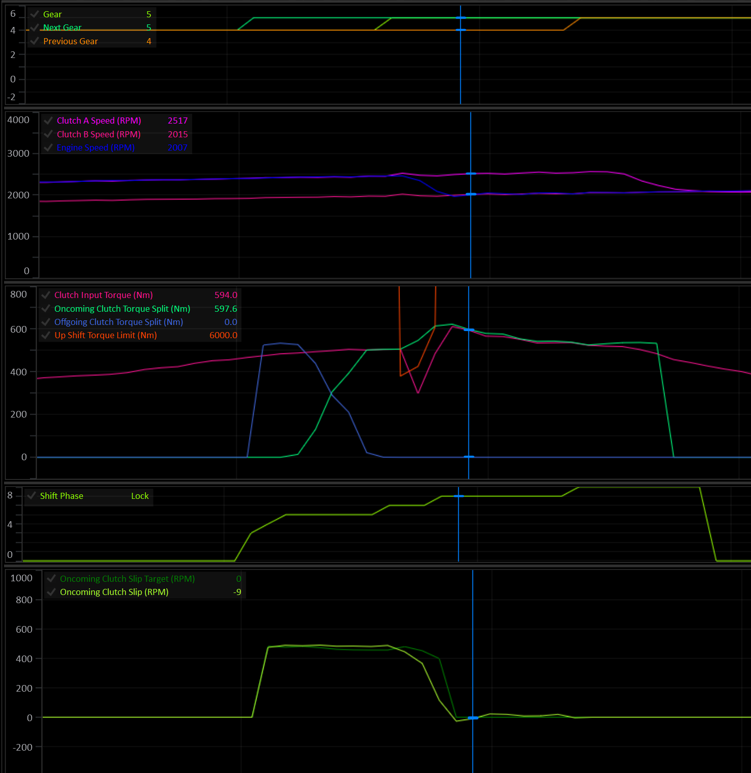
Up shift torque limit gets applied at the start of the Inertial Sync phase and is removed as slip approaches zero.
Tip
If the engine continues to limit torque after the clutch is synced and locked, the shift will feel harsh.
There are 3 tables that control the up shift torque limit:
- Up Shift Torque Limit Enable: determines if a torque limit is allowed or not.
- Up Shift Torque Limit: Absolute explicit torque limit value.
- Up Shift Torque Reduction: Torque reduction as a percentage of Engine Torque (Available).
The lowest torque limit output from the tables will be used.
For Example:
Because 480 Nm is less than the 500 Nm absolute limit, 480 Nm will be used.
Lock Phase
The Lock phase is used to eliminate any remaining clutch slip. A user definable amount of additional torque capacity is applied to the clutch during the lock phase.
Shift Tuning
The torque modelled approach to shifting dramatically reduces the tuning complexity of gear shifts for the end user, provided the input torque is accurate and the Clutch Configuration is accurate.
The goal when tuning a shift is simply to achieve the slip target throughout the shift. If the slip is on target then the only thing left to do is dial in the feel by manipulating the shift target times.
The runtimes to watch are Oncoming Clutch Slip Target and Oncoming Clutch Slip. Ideally they should lay over each other.
If a shift feels harsh, check the slip curve. If the slip is on target, extend the shift times before looking for a way to alter the clutch pressure or clutch torque capacity.
Tuning Considerations:
- The Clutches Geometry Model has the most influence over clutch torque calculations during a shift.
- The amount of torque to added to sync engine speed during the Inertial Sync Phase is determined by the Engine’s Inertia setting. Incorrect engine inertia will result in poor synchronization.
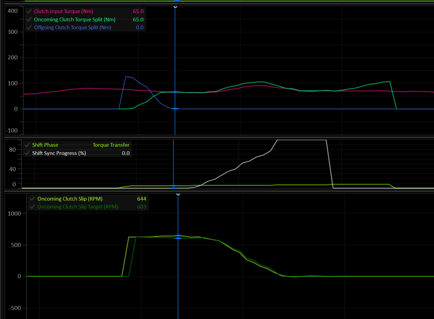
Ideal clutch slip curve during an upshift.
Shift Runtimes
When looking to see what’s happening during a shift there are several important runtime channels to watch:
- Shift Phase: Shows which phase the shift is currently in.
- Clutch Input Torque: This is the torque that all the clutch pressure calculations use as their input reference. Most of the time this is the same as
Engine Torque (Supplied). - Clutch # Input Torque: Each clutch may have a different input torque depending on it’s current Gear Load Factor Table value.
Clutch # Input Torque = Clutch Input Torque x Clutch # Gear Load Factor - Oncoming Clutch Torque Split: During a shift, this is the calculated torque that the oncoming clutch is required to hold. The value seen here is before any closed loop intervention. It’s the raw output of the shift modelling and inertia factors.
- Offgoing Clutch Torque Split: During a shift, this is the calculated torque that the offgoing clutch is required to hold. The value seen here is before any closed loop intervention. It’s the raw output of the shift modelling and inertia factors.
- Oncoming Clutch Slip Target: How much slip the oncoming clutch should have for an ideal shift, to meet the user’s shift time targets.
- Oncoming Clutch Slip: The actual slip of the oncoming clutch. During ideal shift conditions, this will usually lay over the top of the target value. It’s very possible and expected that under some conditions this will not be the case, for example: During a rev-matched downshift where the synchronization of the engine speed is not controlled by the TCM.
- Shift P Gain: Shift closed loop control proportional output.
- Shift I Gain: Shift closed loop control integral output.
- Shift D Gain: Shift closed loop control derivative output.
- Clutch # Torque Capacity: The actual calculated torque capacity of the clutch derived from it’s currently applied pressure. This value is after all closed loop control and rate limiting has been applied.
Touch Points
Important
It is critical that the Clutch Touch Points are setup at the outset. Poorly configured touch points will always lead to bad shifting and drivability.
For detailed information on setting touch points see here.
Clutch Capacity Learning
The Clutches Geometry Model and engine inertia value will control the majority of the clutch torque applied during a shift. During a shift, the closed loop PID algorithm will make adjustments to the final clutch torque to try and keep the slip curve on target. After a shift, as long as the conditions are met, the Clutch Capacity Adaption system will look at the previous shift’s closed loop output and make small adjustments to the relevant clutch’s Learned Capacity Scaler.
Shift Fork Control
This guide covers setup and calibration of the hydraulically actuated Shift Forks used to control gear selection in Dual Clutch Transmissions (DCT).
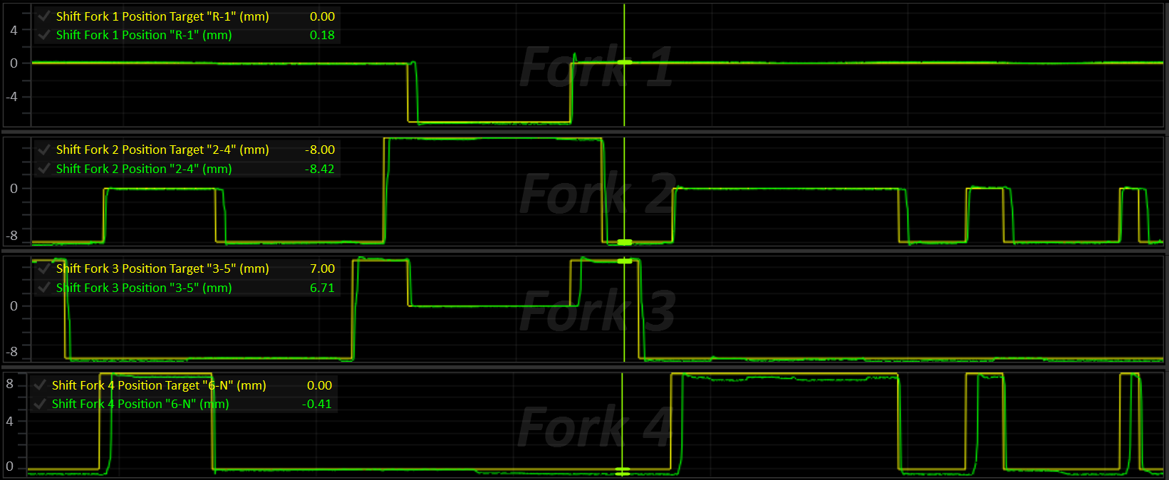
Concepts
Axes
A DCT has two input shafts (“axes”), each carrying its own clutch. While one axis is transmitting drive, the other is free to pre-select the next gear so that the shift itself is just a clutch hand-off, with no torque interruption. Every gear (including Reverse) belongs to one of these two axes:
| Clutch | Axis | Typical Gears |
|---|---|---|
| A | A | Even gears |
| B | B | Odd gears |
The active axis is whichever axis currently has a gear engaged and is transmitting drive.
The inactive axis is free to move its fork(s) to pre-select the next gear.
Clutch Axes
The TCM will always assume that the clutch and axis are a matched pair:
- Clutch A is on Axis A
- Clutch B is on Axis B
Shift Forks
A shift fork is a physical selector that can sit in one of three positions (“slots”):
| Slot | Meaning |
|---|---|
| Low | Engages the fork’s “Low” gear |
| Centre | Neutral (no gear engaged on that fork) |
| High | Engages the fork’s “High” gear |
Each fork belongs to one axis (or, for a shared Reverse fork, both axes) and is responsible for up to two gears, one on its Low side and one on its High side.
Up to 8 forks and 8 shift solenoids are supported.
While driving:
- The active axis must already have its current gear’s fork engaged (all other forks on that axis in Neutral).
- The inactive axis may have, at most, the pre-selected next gear’s fork engaged (all others in Neutral).
Only one fork is ever moved at a time. A fork on the active axis is never moved unless it’s explicitly required (e.g. a shift out of Neutral/Park), and a fork that needs to return to Neutral is always preferred over one that’s about to engage a new gear, so the way is cleared before a new gear goes in.
Fork Position Sensing
Each fork has a position sensor that is scaled and calibrated to report the fork’s measured position in millimeters. Some forks also have a secondary tracking sensor used purely for cross-checking / diagnostics.
Fork Position 1-8 inputs are configured in Input Setup.
The fork’s calibrated Low / Centre / High positions and tolerance bands are what translate this raw position into a slot (Low / Centre / High / Moving).
Fork Management
At all times the shift fork system is actively performing the following tasks:
- Each fork’s target is set:
- Active-axis forks target the current gear.
- Inactive-axis forks target the pre-selected gear.
- Everything else targets Neutral.
- Each fork’s own position/slot state is updated.
- Axis “binding” is detected if more than one fork on an axis reports being in gear at once.
- An axis fault is raised if any fork on that axis is in a position error state.
Fork Movement
- If a fork is currently moving, its movement is monitored until complete.
- Otherwise, the next fork that needs to move is found (inactive axis first, unless an active-axis move is explicitly allowed) and its movement begins.
- The physical shift solenoids are driven to move the current fork, or to hold the idle/default solenoid pattern when nothing is moving.
- If Axis Pressure Control solenoids are in use, their pressure is modulated to control fork movement speed.
- The moving fork is driven either toward its target position (default), or through a series of engagement phases when Engagement Phase Control is enabled.
Shift Procedure
- The currently engaged gear and its axis are marked as active.
- The Preselection system predicts the next shift direction (up or down) and selects the next gear on the inactive axis.
- On a shift request, the next gear’s fork is determined and pre-selected (if it’s not already) on the inactive axis.
- Once the pre-selected gear’s axis is ready (fork in target slot, no axis error), the clutch hand-off for the shift can proceed.
- After the shift completes, the new gear’s axis is marked as active, the offgoing axis is marked inactive.
- The Preselection system resumes prediction of the next shift on the newly inactive axis.
Configuration & Calibration
Shift Fork Setup (Global)
These apply to whichever fork is currently moving, regardless of which fork it is.
| Setting | Description |
|---|---|
| Shift Fork Stable Velocity (+/-) | Fork velocity threshold (± mm/s). Once a fork is inside its target slot’s tolerance band and below this velocity, its “stable” timer starts. Set to 0 to disable the velocity check (stability then depends only on being in-slot) |
| Shift Fork Stable Time | Time (ms) the fork must remain in-slot and stable before the move is considered complete |
| Engagement Phase Control | Selects how a moving fork is driven. OFF = the fork is driven toward its target position. ON = the fork is driven through a series of engagement phases, see Engagement Phase Control |
| Fork Move Idle Target | Idle speed requested from the ECU while a gear is engaged from Neutral or Park at a standstill. Engagement Phase Control only, see Standstill Engagement Aids |
Shift Fork Setup (Per-Fork)
Each fork (numbered 1–8) is independent and must be configured individually. Below, “#” stands for the fork number, eg: “Shift Fork 3 Axis”.
| Setting | Description |
|---|---|
| Shift Fork # Axis | Parent axis: Disabled / Axis A / Axis B / Both (shared, e.g. Reverse) |
| Shift Fork # Label | Free-text label for the fork (shown in the tuning software UI) |
| Shift Fork # Position L Gear | Gear engaged when the fork is in its Low slot. OFF = slot unused. |
| Shift Fork # Position H Gear | Gear engaged when the fork is in its High slot. OFF = slot unused. |
| Shift Fork # Position L | Target fork position for the Low slot (mm) |
| Shift Fork # Centre | Target fork position for the Centre (Neutral) slot (mm) |
| Shift Fork # Position H | Target fork position for the High slot (mm) |
| Shift Fork # Position L Tolerance (+/-) | Position tolerance (± band) around the Low slot (mm) |
| Shift Fork # Centre Tolerance (+/-) | Position tolerance (± band) around the Centre slot (mm) |
| Shift Fork # Position H Tolerance (+/-) | Position tolerance (± band) around the High slot (mm) |
| Shift Fork # Error Detection | Enables position error detection; bit 1 auto-clears the error once the fork returns to its target slot |
| Shift Fork # Error Auto Clear | Auto-clears the error once the fork returns to its target slot |
| Shift Fork # Error Delay | Time the fork may be out of its target slot before a position fault is raised (0–25.0 s) |
| Shift Fork # Retry Limit | Number of retries allowed after the first attempt before the fork raises a position fault. 0 = a single attempt only. See Per-Fork Position Error and Stalls and Retries |
| Shift Fork # Test | Bench/service test override: Off / Force Low, / Force Centre, / Force High. Only takes effect while the requested gear is Neutral or Park |
Notes:
- The Low and High slot positions do not need to be numerically low/high — the firmware automatically detects whether the fork’s travel is inverted (i.e. the Low position is a larger number than Centre) and corrects the shift-direction logic accordingly.
- Whichever gear ends up on the Low slot vs. High slot is purely a function of fork travel direction — set the Low/High gear assignments to match the physical gear each end of travel actually engages.
- A fork does not need both slots populated — a single-sided fork (e.g. Reverse-only) should leave the unused Low/High gear assignment at
0.
Shift Solenoid Selection
Which solenoids are energised to move a fork in a direction is controlled by the solenoid select tables.
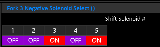
| Table | Description |
|---|---|
| Shift Fork # Positive Solenoid Select | Selects which shift solenoid(s) (1–8) are energised to move the fork in the positive position direction (+ mm) |
| Shift Fork # Negative Solenoid Select | Selects which shift solenoid(s) (1–8) are energised to to move the fork in the negative position direction (- mm) |
| Shift Fork Idle Solenoid Select | Shift solenoid(s) held on when no fork is currently moving (idle hold pattern) |
| Default Shift Solenoid Select | Shift solenoid(s) always added to the active pattern in addition to the moving/idle pattern, when the default overlay is enabled |
| Default Shift Solenoid Enable | Enables/disables the default solenoid overlay above (non-zero = enabled) |
Important
The solenoid select table’s X-axes must be Shift Solenoid #. Multiple solenoids can be selected at once.
Per-Fork Position Sensor Calibration
Shift Fork n Position is reported in mm.
Each fork has a position sensor that can be calibrated in Input Config > Transmission Inputs > Shift Fork Positions.
It is critical that these position sensor inputs are assigned and calibrated correctly.
Fork Movement Pressure Control
While a fork is moving, its physical movement can optionally be driven by a
closed-loop position PID acting on hydraulic pressure (rather than a fixed pressure). The need for pressure control will depend on the transmission design.
When enabled, the Axis Pressure solenoids are controlled to achieve the desired pressure.
With Engagement Phase Control ON, the PID is not used. The pressure is instead set by the force of the current engagement phase, as a percentage of the maximum fork movement pressure (see Engagement Phase Control).
| Setting / Table | Description |
|---|---|
| Axis Pressure Override | Enables the axis pressure override: while set, the axis pressure of whichever axis is physically moving is driven by the fork-movement PID (or by Engagement Phase Control) instead of the normal active/inactive axis pressure targets |
| Fork Movement Pressure Base | Base (feed-forward) pressure added ahead of the PID output (Bar). Engagement Phase Control OFF only |
| Fork Movement Pressure Proportional Gain | PID proportional gain for fork movement pressure control. Engagement Phase Control OFF only |
| Fork Movement Pressure Integral Gain | PID integral gain for fork movement pressure control. Engagement Phase Control OFF only |
| Fork Movement Pressure Derivative Gain | PID derivative gain for fork movement pressure control. Engagement Phase Control OFF only |
| Axis Pressure Override Integral Min / Max | PID integral clamp (Bar). Engagement Phase Control OFF only |
| Axis Pressure Override Min / Max | Output pressure clamp (final PID output is constrained to this range) (Bar) |
| Fork Movement Pressure Max | Maximum fork movement pressure (Bar). The lower of this table and Axis Pressure Override Max is used. 0 = use Axis Pressure Override Max. With Engagement Phase Control ON, this is the pressure that equals 100% fork force |
Fork Movement Current Control
Transmissions that set fork force through the shift solenoid current rather than axis pressure (e.g. Getrag GS7) use Variable Force shift solenoids. While a solenoid is energised, its current is taken from its Shift Solenoid # Current table. The table’s axis can be chosen to suit the fork movement mode:
| Table Axis | Behaviour |
|---|---|
Active Shift Fork Position Error | High current far from the target slot, tapering as the fork arrives. Suits position control (Engagement Phase Control OFF). |
Shift Fork Force Demand | Current follows the force requested for the fork (0 - 100%), so the table becomes a force-to-current map. Required for Engagement Phase Control. |
Leave Axis Pressure Override OFF on these transmissions.
Torque Limiting During Fork Movement
Active Axis Fork Movement Torque Limit can be applied applied while a fork on the currently active axis is moving (e.g. Shifts out of Neutral/Park, where the axis being engaged is also the “active” axis).
Engagement Phase Control
Engagement Phase Control is an alternative way of driving a moving fork, built around how a synchroniser engages a gear. Instead of simply pushing the fork toward its target position, the TCM steps the fork through a series of phases (approach, synchronise, engage and settle), each with its own force. If the fork stalls, it’s backed off, rested and tried again with a little more force, rather than being held hard against the synchroniser.
This makes the biggest difference when engaging a gear from Neutral or Park at a standstill, where drag from the open clutch keeps the shaft spinning. A fork that is just pushed harder tends to sit on the synchroniser, using it as a brake against the clutch drag. Engagement Phase Control detects this, backs off and retries, and limits how hard and how long the synchroniser is worked.
It works with both pressure-actuated forks (e.g. Nissan GR6) and forks whose force is set by the shift solenoid current (e.g. Getrag GS7).
Enabling Engagement Phase Control
Set Engagement Phase Control to ON in Shift Fork Setup. The Shift Fork Engagement Phase Control folder will then appear, containing the settings and tables described below.
All fork forces are set as a percentage (0 - 100%) of the fork’s maximum force. How that percentage is turned into an output depends on how the forks are actuated:
| Fork Actuation | Setup |
|---|---|
| Axis Pressure (e.g. Nissan GR6) | Set Axis Pressure Override to ON. 100% force is the lower of Fork Movement Pressure Max and Axis Pressure Override Max. Axis Pressure Override Min sets the minimum pressure while a fork is moving. The fork movement PID tables are not used. |
| Shift Solenoid Current (e.g. Getrag GS7) | Leave Axis Pressure Override OFF. Set the Solenoid Type of the shift solenoids that move the forks to Variable Force, and set the axis of each of their Shift Solenoid # Current tables to Shift Fork Force Demand. The table then converts the requested force (%) into solenoid current. |
Axis Pressure Example
- Fork Movement Pressure Max = 18.0 Bar
- Current phase force = 40%
- Fork movement pressure = 40% of 18.0 Bar = 7.2 Bar
Fork Travel and Sync Slip
Two channels are central to how Engagement Phase Control works, and to tuning it:
Shift Fork Travelis the moving fork’s progress, from 0% at the slot it’s leaving to 100% at its target slot. Where the synchroniser sits within that travel is set by Sync Zone Start and Sync Zone End. The sync zone is shared by all forks in both directions, so it must cover every fork’s synchroniser.Shift Fork Sync Slipis the speed difference the synchroniser has to remove before the gear can engage: the speed of the target axis clutch compared to the speed the target gear would turn it at. The shaft is considered synchronised once this falls below Synchro Slip Complete Threshold. Correct clutch speed and output shaft speed readings are required.
Move Phases
Each fork move steps through the following phases, reported by Shift Fork Move Phase:
| Phase | Description |
|---|---|
| Idle | No fork is moving. |
| Approach | The fork leaves its slot at Shift Fork Approach Force and travels toward the synchroniser, until it reaches Sync Zone Start. |
| Sync | The synchroniser is loaded. Force starts at Shift Fork Sync Force Start and rises at Sync Force Ramp Rate up to the force ceiling for this attempt (Sync Force Max on the first attempt). Sync ends once the blocker ring releases and the fork passes Sync Zone End. |
| Engage | The blocker ring has released and the fork rides the dog teeth into the slot. Once the shaft is synchronised, the force changes to Shift Fork Engage Force. Until then, the force the ring released at is held, as the ring lets go slightly before the shaft is fully synchronised. If the fork is pushed back onto the ring, it returns to Sync. |
| Settle | The fork has reached its target slot and the shift solenoids are off. The move is complete once the fork has been stable in the slot for Shift Fork Stable Time (see Shift Fork Stable Velocity). If the fork bounces out of the slot, the solenoids stay off until it has come to rest, so a fork overshooting Neutral isn’t pushed back and forth between the two directions. If it comes to rest outside the slot, it’s driven back in. |
| Back Off | After a stall, the fork is pulled back toward the slot it came from by Back-Off Distance at Back-Off Force, for no longer than Back-Off Time. The fork is never pulled back past the slot it came from. |
| Rest | The shift solenoids are turned off for Retry Rest Time, allowing the synchroniser to re-centre before the next attempt. |
| Error | All attempts have been used. The fork enters its position error state, see Per-Fork Position Error. |
A fork returning to Neutral has no synchroniser to work against, so it goes straight from Approach to Engage.
Stalls and Retries
When a fork stops making progress toward its target, the TCM records why in Shift Fork Stall Type, backs the fork off, rests, then tries again.
| Stall Type | Phase | Cause |
|---|---|---|
| None | - | No stall has occurred during this move. |
| Mechanical | Approach | The fork stopped making progress for Approach Stall Time, or didn’t reach Sync Zone Start within Approach Timeout. The stall timer only starts once the fork has begun to move. |
| Blocker Ring | Sync | The blocker ring didn’t release within Sync Timeout. Or, the shaft was synchronised but the fork didn’t move for Synchro Settled Timeout with the force at its ceiling (clutch drag is holding the ring in place). |
| Equilibrium | Sync | With the force at its ceiling, Shift Fork Sync Slip didn’t fall by at least Synchro Slip Progress Validation within each Synchro Slip Progress Window. The synchroniser can’t overcome the clutch drag, so the attempt is abandoned early rather than using the synchroniser as a brake for the full Sync Timeout. |
| Dog Teeth | Engage | The fork sat, or bounced, on the dog teeth without making progress for Dog Engagement Stall Time. |
Retries work as follows:
- Each retry raises the Sync force ceiling by Sync Retry Force Step (up to 100%). The first attempt can be gentle, with force only increasing when the synchroniser needs it.
- Each fork is allowed its Shift Fork # Retry Limit retries after the first attempt. Once they have all failed, the fork enters its position error state.
- The fork’s Error Delay still limits the total time of the whole move, including every attempt.
- After a synchroniser stall (Blocker Ring or Equilibrium), the rest ends early as soon as the shaft is synchronised.
- After a Dog Teeth stall, the rest ends early as soon as the shaft has turned relative to the gear, giving the teeth a new position to engage.
Shift Fork Crash Count counts (per fork, since power up) engagements where the dog teeth went in while the shaft was still slipping above Synchro Slip Complete Threshold, i.e. the gear was forced through the synchroniser. A rising count means the Sync force ceiling is too high, or there is too much drag on the target axis.
Synchroniser Heat Protection
Repeated attempts heat the synchroniser. Shift Fork Sync Energy estimates this for each fork by accumulating slip x force x time while the synchroniser is loaded, and decays over roughly 20 seconds.
While Shift Fork Sync Energy is above Sync Energy Limit, the rest between attempts is extended from Retry Rest Time to Sync Energy Limit Cooldown. Set Sync Energy Limit to 0 to disable.
Standstill Engagement Aids
Two optional functions help engage a gear from Neutral or Park while the vehicle is stationary.
Dog Engagement Stall Clutch Pulse
If the fork stalls on the dog teeth with the shaft already synchronised, the teeth are likely sitting tip to tip. When enabled, the target axis clutch is briefly applied during the rest, at its touch point + Dog Engagement Stall Clutch Pulse Pressure for Dog Engagement Stall Clutch Pulse Time. This turns the shaft a few degrees so the teeth can line up on the next attempt.
- Only the clutch on the axis being engaged is pulsed, and only while nothing is engaged on that axis.
- It’s never used after a synchroniser stall.
Shift Fork Clutch Pulse Statusis ON while the pulse is applied, and the clutch status reportsOn - Shift Fork Clutch Pulse.
Fork Move Idle Target (Shift Fork Setup)
A lower engine idle speed means less clutch drag for the synchroniser to overcome. While a gear is being engaged from Neutral or Park at a standstill, the Fork Move Idle Target is output on Shift Fork Idle Speed Request (0 at all other times). To use it, transmit Shift Fork Idle Speed Request to the ECU in a CAN message and configure the ECU to use it as its idle target. Set to 0 to disable.
Engagement Phase Settings
Found in Shift Fork Engagement Phase Control > Shift Fork Engagement Phase Setup.
| Setting | Description |
|---|---|
| Approach Stall Time | Time the fork may go without making progress during Approach before a Mechanical stall is declared. The timer only starts once the fork has begun to move, so it doesn’t need to allow for break-away (ms) |
| Approach Timeout | Approach must reach Sync Zone Start within this time, or a Mechanical stall is declared (ms) |
| Sync Zone Start | Fork travel at which the fork reaches the blocker ring and the Sync phase begins (0% = slot being left, 100% = target slot). Set comfortably below the travel where forks are seen to stall on the synchroniser (%) |
| Sync Zone End | Fork travel at which the blocker ring is considered released and the Engage phase begins. Set above the highest synchroniser stall position, and below where the dog teeth are reached (%) |
| Sync Timeout | Longest time the synchroniser is loaded in one attempt before the fork backs off. Limits synchroniser heating (ms) |
| Sync Force Ramp Rate | Rate the force rises from Shift Fork Sync Force Start up to the force ceiling. A slow ramp spends longer at a force where the synchroniser can work. A fast ramp reaches the ceiling quickly and is more likely to push through the blocker ring before the shaft is synchronised (%/s) |
| Sync Force Max | Force ceiling for the first attempt. Should be below the force that pushes the fork through the blocker ring while the shaft is still spinning (%) |
| Sync Retry Force Step | Added to the force ceiling on each retry, up to 100% (%) |
| Synchro Slip Progress Validation | With the force at its ceiling, Shift Fork Sync Slip must fall by at least this much every Synchro Slip Progress Window, or an Equilibrium stall is declared (RPM) |
| Synchro Slip Progress Window | Time window over which slip progress is checked (ms) |
| Synchro Slip Complete Threshold | Shift Fork Sync Slip below which the shaft is considered synchronised (RPM) |
| Synchro Settled Timeout | If the shaft is synchronised with the force at its ceiling, but the fork isn’t moving for this long, a Blocker Ring stall is declared so the ring can re-centre (ms) |
| Sync Energy Limit | Synchroniser heat limit, compared with Shift Fork Sync Energy. 0 = disabled |
| Sync Energy Limit Cooldown | Rest time used instead of Retry Rest Time while the synchroniser is over its Sync Energy Limit (ms) |
| Dog Engagement Stall Time | Time the fork may go without making progress on the dog teeth during Engage before it backs off (ms) |
| Back-Off Distance | How far the fork is pulled back toward the slot it came from after a stall. Enough to fully unload the blocker ring or clear the dog teeth (mm) |
| Back-Off Time | Longest time the back off is driven if Back-Off Distance isn’t reached (ms) |
| Back-Off Force | Force used to pull the fork back after a stall. It only needs to unload the ring or lift the fork off the dog teeth, not move quickly (%) |
| Retry Rest Time | Time the shift solenoids are off between attempts (ms) |
| Dog Engagement Stall Clutch Pulse | Enables the dog stall clutch pulse, see Standstill Engagement Aids |
| Dog Engagement Stall Clutch Pulse Pressure | Pressure above the clutch touch point applied during the pulse. Just enough to turn an unloaded shaft (Bar) |
| Dog Engagement Stall Clutch Pulse Time | Length of the pulse. The rest between attempts is held until the pulse has finished (ms) |
Force Tables:
| Table | Description |
|---|---|
| Shift Fork Approach Force | Force from leaving the slot until the fork reaches Sync Zone Start. Enough to move the fork briskly, without throwing it at the blocker ring. Too low and the fork won’t break away, resulting in a Mechanical stall (%) |
| Shift Fork Sync Force Start | Force when the fork first loads the blocker ring. The synchroniser works best at a moderate force, so starting low gives it a chance to synchronise the shaft before the force ramps up. Consider spanning this table against Output Shaft Speed, so pre-selection while driving starts closer to the ceiling and only standstill engagements start gently (%) |
| Shift Fork Engage Force | Force used to push the fork through the dog teeth into the slot once the shaft is synchronised. Too low and the fork will stall on the dog teeth. Too high and it will slam into the slot (%) |
Tuning Engagement Phase Control
Complete the standard Calibration Procedure first. Fork travel is measured between the calibrated slot positions, so these must be accurate.
Check
Shift Fork Sync Slipreads sensibly during a fork movement. It relies on correct clutch speed and output shaft speed readings.Set up the force range for the fork actuation type, see Enabling Engagement Phase Control.
Enable Engagement Phase Control and log a number of engagements from Neutral at a standstill, as well as pre-selections while driving. Log
Shift Fork Move Phase,Shift Fork Stall Type,Shift Fork Move Attempt,Shift Fork Travel,Shift Fork Sync Slip,Shift Fork Force DemandandShift Fork Crash Count, along with each fork’s Position.Set the sync zone from
Shift Fork Travelat the point where each fork stalls on the synchroniser. Sync Zone Start should be below the lowest stall point, and Sync Zone End above the highest.Set Shift Fork Sync Force Start low enough that the synchroniser has a chance to work before the force ramps up to its ceiling. Only then raise Sync Force Max if forks still fail to engage.
Watch
Shift Fork Crash Count. A rising count means the force ceiling is overpowering the blocker ring rather than letting the synchroniser work. The fix is less force or less drag (e.g. a lower idle with Fork Move Idle Target), not more force.Review stall types at a standstill. Repeated Equilibrium stalls mean clutch drag is too high for the synchroniser to overcome, so reduce drag rather than adding force. Repeated Dog Teeth stalls with the shaft synchronised can be helped by the Dog Engagement Stall Clutch Pulse.
Set each fork’s Retry Limit and Error Delay last, once engagement is reliable.
Errors & Diagnostics
Per-Fork Position Error
If a fork’s error-detection is enabled, a fork that fails to reach its target slot within its Error Delay (or whose position sensor reports a fault) raises a Fork # Movement fault and enters an internal error state.
From the error state, the firmware automatically retries the move, up to the fork’s Retry Limit, 1 second apart. With Engagement Phase Control ON, retries are made within the move itself (see Stalls and Retries), so there are no further automatic retries once the fork has entered the error state. If Error Auto Clear is enabled, the error clears automatically once the fork successfully reaches its target slot again (and the position sensor is healthy) — this is normally only allowed to happen when the fork’s target is Centre (Neutral), so a fork always has to prove it can get back to a safe state before being trusted again.
Using the tuning software’s “Clear All Codes” action also resets every fork’s retry count, in addition to clearing the fault codes themselves — so a fork that had exhausted its retries gets a fresh set of attempts on its next movement, rather than immediately re-latching into a fault.
Axis errors
Each axis is also monitored as a whole:
| Fault | Cause |
|---|---|
| Axis A Bound / Axis B Bound | More than one fork on that axis reports being in gear simultaneously — i.e. the axis is mechanically bound between two gears |
| Axis A Fault / Axis B Fault | At least one fork on that axis is in a position error state |
While an axis is in fault, no fork on that axis will be moved until the fault clears.
Related channels for diagnosis
See Runtime Channels for the full list. Each fork’s Status and Position Error, and the Moving Shift Fork channel, are usually the first things worth logging when diagnosing a shift fork issue.
Runtime Channels
Per-Fork Channels (# = fork number, 1–8):
| Channel | Description |
|---|---|
| Shift Fork # Position | Measured fork position, mm |
| Shift Fork # Position Target | Target fork position, mm |
| Shift Fork # Position Error | Position error (target − measured), mm |
| Shift Fork # Velocity | Measured fork velocity, mm/s |
| Shift Fork # Status | see Shift Fork Status enumeration |
| Shift Fork # Tracking | Secondary/tracking position sensor reading (diagnostic only) |
System-Wide Channels:
| Channel | Description |
|---|---|
| Selected Gear A | Gear currently engaged on Axis A |
| Selected Gear B | Gear currently engaged on Axis B |
| Active Gear Shift Fork | Fork responsible for the currently active (engaged) gear |
| Preselected Gear Shift Fork | Fork responsible for the pre-selected next gear |
| Moving Shift Fork | Fork currently moving |
| Active Shift Fork Position | Position of whichever fork is currently moving |
| Active Shift Fork Position Target | Target position of whichever fork is currently moving |
| Active Shift Fork Position Error | Position error of whichever fork is currently moving |
| Active Axis Pressure Target | Active axis clutch pressure target, Bar |
| Inactive Axis Pressure Target | Inactive axis clutch pressure target, Bar |
| Active Axis Fork Movement Torque Limit | Torque limit currently applied due to active-axis fork movement |
| Shift Fork Movement Pressure | Fork movement pressure demand output, Bar |
| Shift Fork Movement Pressure Base | Fork movement pressure base/feed-forward term |
| Shift Fork Movement Pressure P Gain | Fork movement pressure PID proportional term |
| Shift Fork Movement Pressure I Gain | Fork movement pressure PID integral term |
| Shift Fork Movement Pressure D Gain | Fork movement pressure PID derivative term |
| Shift Fork Force Demand | Force requested for the moving fork, % of maximum. Also reported with Engagement Phase Control OFF while Axis Pressure Override is ON |
Engagement Phase Control Channels:
| Channel | Description |
|---|---|
| Shift Fork Move Phase | Phase of the moving fork, see Shift Fork Move Phase enumeration |
| Shift Fork Stall Type | Reason for the most recent back off, see Shift Fork Stall Type enumeration and Stalls and Retries |
| Shift Fork Move Attempt | Attempt number of the current move, 1 = first attempt. 0 when no fork is moving |
| Shift Fork Phase Time | Time spent in the current phase, ms |
| Shift Fork Travel | Fork progress from the slot it’s leaving (0%) to its target slot (100%) |
| Shift Fork Sync Slip | Speed difference the synchroniser has to remove, RPM. 0 for a return to Neutral |
| Shift Fork Crash Count | Number of engagements of the moving fork, since power up, where the dog teeth went in with the shaft still slipping |
| Shift Fork Sync Energy | Heat estimate for the moving fork’s synchroniser, compared with Sync Energy Limit |
| Shift Fork Clutch Pulse Status | ON while the Dog Engagement Stall Clutch Pulse is applied |
| Shift Fork Idle Speed Request | Idle speed requested from the ECU during a standstill engagement, RPM. 0 when not requested |
Calibration Procedure
Enable each fork — set the Axis setting for every physical fork fitted (Axis A, B, or Both for a shared Reverse fork). Leave unused fork slots OFF.
Wire up and calibrate position sensors first, via the standard analog input mapping/translation tools, so that each fork’s Position channel reads a correctly-scaled value (mm) across the whole range of travel.
Set tolerance bands (Low/Centre/High Tolerance) tight enough to confirm the dog teeth/synchro are actually engaged, but loose enough to tolerate normal sensor noise and mechanical play.
Assign gears to each slot via Position L Gear / Position H Gear. You may have to put some educated guesses into the positions initially.
Assign shift solenoids per fork (Positive/Negative Solenoid Select) and confirm direction — command a move with Test mode and verify the fork moves the correct way and its Status reports moving in the expected direction, then settles into the correct slot.
Set idle/default solenoid patterns (Idle Solenoid Select, Default Select / Enable) as required by the actuator hardware.
Find and record the three slot positions for each fork with the vehicle safely supported and the driveline free to move by hand, or using the fork’s Test setting to command it to each slot in turn (only works while the requested gear is Neutral or Park):
- Force to Low, record the settled Position reading into Position L.
- Force to Centre, record Centre position.
- Force to High, record Position H.
- Set Test back to Off when done.
Tune move-complete detection — Stable Velocity and Stable Time — so a fork isn’t reported as “done” while still settling, but without adding unnecessary delay to every shift.
Tune fork movement pressure (if using closed-loop pressure control): set the Movement Pressure Base and PID gains, and the Pressure Override Min/Max and Integral Min/Max clamps, then set Axis Pressure Override to ON if pressure-based fork actuation is desired instead of fixed axis pressure targets. If using Engagement Phase Control, follow Tuning Engagement Phase Control instead.
Set error detection last, once movement is proven reliable. Set each fork’s Error detect / Auto-Clear and Error Delay, generous enough to allow for normal shift timing but tight enough to catch a stuck fork.
Verify full shift sequences in all gears, both directions, watching the Active Gear Shift Fork, Preselected Gear Shift Fork and Moving Shift Fork channels. Watch each fork’s Status & Position, for consistent, movement and engagement. Confirm no Axis Bound/Axis Fault faults occur across the full gear range.
Takeup
Takeup manages the smooth application (and release) of clutch torque from a standing start. The equivalent of a driver gently feeding out a manual clutch pedal, done automatically. It’s a critical function for dual-clutch transmissions, and an optional feature on multi-clutch transmissions that are also equipped with a torque converter.
Takeup doesn’t select gears or bring in extra clutches on its own — it only takes over the pressure of whichever clutch is already engaged for the current gear, for as long as the car is moving off from (or slowing to) a stop.
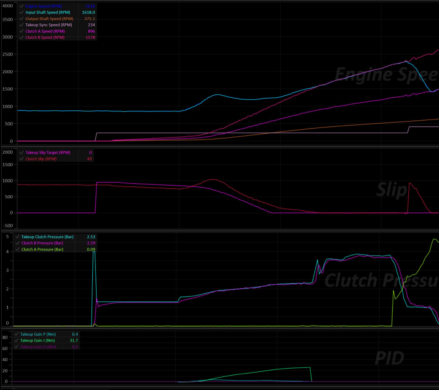
Enabling and Selecting the Clutch
Set Enable to turn Takeup on. Once enabled, the Takeup Clutch Select table determines which clutch Takeup is allowed to take control of, per gear. This only has effect for a clutch that’s already part of the active clutch set for the current gear; it cannot bring in a clutch on its own. Configure one clutch per gear for a standard standing-start setup.
Takeup Clutch Select Table
- X Axis: MUST be
Clutch #. - Y Axis: MUST be
Gear.
Select a clutch for each gear, even if it’s not intended for normal operation.
If a clutch is not selected for the current gear, the Takeup system will not arm in that gear. In the event of a failure where the transmission is forced to stay in a unintended gear, this may result in the car being undriveable.
Speed Target Mode
Speed Target Mode sets what the closed-loop slip controller is trying to synchronize to.
| Mode | Behaviour |
|---|---|
| Off | Takeup Target Mode is 0 — Takeup is disabled regardless of the Enable setting. |
| Engine Speed | The Takeup Engine Speed Target table gives a target Engine Speed. The controller works out the clutch slip and synchronous Output Shaft Speed needed to bring the engine to that RPM in the current gear. |
| Input Shaft Speed | The Takeup Input Shaft Speed Target table gives a target Input Shaft Speed directly, again converted to a slip target and synchronous Output Shaft Speed for the current gear. |
| Clutch Slip | The Takeup Slip Target table is used directly as a raw the clutch slip target. No speed synchronization is calculated. |
In all three modes, as the car accelerates and Output Shaft Speed approaches the calculated Takeup Sync Speed, the required slip target tapers down toward zero — this is what lets the clutch lock up smoothly instead of stepping straight from “slipping” to “locked”.
Takeup States
Takeup is a 5-state machine:
| State | Meaning |
|---|---|
| Off | Function disabled, or just enabled while already moving faster than the Arming Output Shaft Speed. |
| Ready | Car stopped/slow. Clutch is held at a small Initial Clutch Torque (optionally preceded by a Fast Fill pulse). Waiting for the driver to get on the throttle. |
| Active | The car is actually launching. A closed-loop controller slips the clutch through to lock-up, tracking the Speed Target Mode’s target. |
| Exit | Takeup Sync Speed and Takeup Slip Target have been met. Pressure ramps the rest of the way up to full lock-up at a dedicated rate. |
| Driving | Fully locked, normal driving. Takeup is watching Output Shaft Speed in the background in case the car slows back down to a stop. |
Ready → Active
The transition from Ready to Active happens once all of the following are true:
- Brake Switch is off
- Pedal/Throttle is above Pedal/Throttle Min
- Engine Torque (Supplied) is above Engine Torque Min.
The system transitions back to Ready if any of the same three conditions reverse (with a small amount of built-in hysteresis so it doesn’t chatter back and forth right at the threshold).
Ready → Exit
If the car picks up speed past Takeup Sync Speed while still in Ready, before the driver has touched the pedal (e.g. rolling away on a hill, or creeping forward under a positive Initial Clutch Torque), Takeup skips Active and goes straight to Exit. The clutch is ramped up to full lock at the Takeup Exit Pressure Ramp Rate rather than sitting at Initial Clutch Torque while the car outruns it. This doesn’t happen while Bleed Off is active.
Active → Exit
Once Output Shaft Speed has risen above the calculated Takeup Sync Speed and Clutch Slip has fallen below the Exit Slip Threshold, the system hands off to the Exit state. The clutch pressure is ramped the rest of the way to full pressure at the Takeup Exit Pressure Ramp Rate.
If Output Shaft Speed falls back below Takeup Sync Speed (minus Output Shaft Speed Sync Hysteresis) before the ramp finishes, it returns to Active rather than continuing to lock up.
Exit → Driving
Once the ramped pressure has caught up to the normal fully-locked clutch pressure, Takeup hands off to the Driving state and stops actively managing that clutch’s pressure.
Driving → Active (coming back down to a stop)
Takeup continuously compares Output Shaft Speed against a re-arming point: Takeup Sync Speed (minus Output Shaft Speed Sync Hysteresis), optionally adjusted earlier by Decel Arming Lead Time during a fast deceleration so the release has a head start rather than only reacting once the car has nearly stopped.
If Arming Output Shaft Speed is set above 0, Output Shaft Speed must also drop below that fixed speed before Takeup re-arms. Set it to 0 to rely on the synchronous-speed comparison alone.
Caution
Pay attention to the table axis setup of the selected slip target table. The Takeup Sync Speed will likely move around if the table is spanned against channels such as Pedal Position. This can result in unintended Takeup re-arming. The Arming Output Shaft Speed setting is useful for eliminating this concern.
Stall-Saver: If Output Shaft Speed drops to the point that Input Shaft Speed would fall below the transmission’s configured Input Shaft Speed Min, Takeup re-arms immediately regardless of the above.
The same re-arming point also gates the way back out. Active (and Ready, when the car rolls past sync on its own) won’t hand off to Exit until Output Shaft Speed is above the re-arming point plus Output Shaft Speed Sync Hysteresis (or above Takeup Sync Speed, whichever is higher). This stops a fast coast-down from bouncing between Exit and Active, which would otherwise show up as a saw-tooth on the clutch pressure.
Lockouts
Takeup is held out of operation — clutch pressure and state are frozen — whenever any of the following are true:
| Lockout | Condition | Cooldown |
|---|---|---|
| Engine stopped | Engine Speed = 0 RPM | — |
| Neutral / Park | Selected Gear = Neutral or Park | — |
| User Lockout | The assigned User Function is OFF (only checked if one is assigned) | — |
| Clutch By Wire | Clutch By Wire Scaler is below Clutch By Wire Lockout (set the lockout to 100% to disable this check entirely) | Clutch By Wire Lockout Cooldown Time |
| Transbrake | Enabled via Transbrake Lockout; trips while the Transbrake is on or in its bump cooldown | Transbrake Lockout Cooldown Time |
| Launch Control | Enabled via Launch Control Lockout; trips while Launch Control is active | Launch Control Lockout Cooldown Time |
The Clutch-By-Wire, Transbrake, and Launch Control lockouts each have their own cooldown timer. Once the underlying condition clears, Takeup stays locked out for the configured cooldown period before it’s allowed to resume, rather than snapping back on the instant the condition goes away. When Takeup comes back out of one of these three lockouts, it re-evaluates whether the car is already moving fast enough to go straight to Driving, or whether it should resume in Ready.
Tip
If Takeup is enabled alongside Launch Control’s clutch override, it’s strongly recommended to enable the Launch Control Lockout so the two systems don’t fight over the same clutch.
Bleed Off
When enabled, Bleed Off removes all pressure from the takeup clutch, so it’s ready to fill from empty. It can be triggered by the Brake Switch (Bleed Off with Brake Switch) and/or the Takeup Bleed Off Enable table.
Two optional lockouts prevent Bleed Off from kicking in:
- Bleed Off Pedal/Throttle Max
- Bleed Off Output Shaft Speed Max
Above either one, Bleed Off is locked out even if the brake/table would otherwise call for it. Setting one of these lockouts to 0 will disable that particular check.
Fast Fill
Once Bleed Off ends (e.g. the brake is released), the clutch chamber has to be filled from empty before it can hold any torque. Fast Fill Pressure and Fast Fill Time open the solenoid to a higher target pressure for a short period to fill the chamber quickly.
Too much of either and the clutch will grab; too little and take-up will feel soft/delayed.
Initial Clutch Torque
After the fill, the clutch is held at Takeup Initial Clutch Torque (a torque value, converted to a pressure using the clutch’s own torque/pressure model and touch point) while waiting in Ready for the driver to get on the throttle. A positive value here makes the car creep, like a manual gearbox car with the clutch slightly out.
Active State: Closed-Loop Control
Once Active, clutch torque is the sum of a feed-forward term and a PID correction, clamped to Takeup Torque Min/Takeup Torque Max, then converted to a pressure via the clutch’s torque/pressure model and added to its touch point.
Feed forward — set via Torque Feed Forward Mode:
- User Defined — looked up directly from the Takeup Clutch Torque Feed Forward table.
- Calculated (Experimental) — derived automatically from input shaft torque and the current slip ratio. It’s recommended to start with the User Defined table and let the PID do most of the work rather than relying on the experimental mode.
PID control closes the gap between actual clutch slip and the target computed from Speed Target Mode, using:
- Proportional Gain
- Integral Gain
- Derivative Gain
- Integral Min / Integral Max
The resulting torque command is converted to pressure and then rate-limited by Takeup Pressure Positive Ramp Rate/Takeup Pressure Negative Ramp Rate so the clutch can’t be commanded to move faster than the driveline can physically respond to.
An engine torque limit (optional, via Torque Limit = ON in Takeup Setup) applies the Takeup Engine Torque Limit to the engine while the clutch is actively slipping, to stop the slipping clutch from being overdriven (see Engine Torque Limiting).
Engine Torque Limiting
Two separate, independent torque limits can apply while Takeup is running:
- Takeup Engine Torque Limit: Applies continuously while the clutch is in Active or Exit (i.e. actively slipping). This protects the slipping clutch from being overdriven by the engine.
- Shift Torque Limit: Applies only if a gear shift starts while Takeup is Active — it caps engine torque to 0 Nm for the duration, to stop the engine flaring and the clutch grabbing hard as the shift completes and control hands back to Takeup.
Both limits automatically defer to Launch Control’s torque limit if Launch Control is also active, so the two functions don’t fight each other.
Interaction with Automatic Shifting
Suppress Auto Mode Up Shifts During Takeup and Suppress Auto Mode Down Shifts During Takeup independently block automatic up/down shifts for as long as Takeup is actively slipping the clutch (Active or Exit), so a shift can’t be requested out from under an in-progress launch. Manual shift requests are not affected.
Runtime Channels
The Takeup system generates the following runtime channels:
- Takeup Status (see Takeup Status enumeration)
- Takeup Slip Target
- Takeup Slip Error
- Takeup Sync Speed
- Takeup Clutch Pressure
- Takeup Torque Feed Forward
- Takeup Clutch Torque
- Takeup Gain P
- Takeup Gain I
- Takeup Gain D
Torque Converter Lockup
The torque converter lockup clutch mechanically joins the engine to the transmission input, bypassing the converter’s fluid coupling. With the clutch locked there is no converter slip: less heat in the transmission oil, better fuel economy, and a direct connection between the throttle and the wheels. With it unlocked the converter can slip and multiply torque, which helps launches and low-speed driving.
The TCM decides when the lockup clutch should be locked or unlocked, how much pressure to apply, and how quickly to apply and release it. Each of these can be tuned separately for each phase of operation (takeup, launch, in gear, up shifts and down shifts).
Torque Converter Lockup applies to transmissions with a torque converter, such as the ZF 8HP. Dual-clutch transmissions don’t have a converter and don’t use it.
Enabling
Assign the lockup solenoid to an output in Output Config > Transmission Functions (Torque Converter Lockup Solenoid Output). Once an output is assigned, the Torque Converter Lockup folder appears.
The TC Lockup Setup page holds the general settings:
| Setting | Description |
|---|---|
| Output | The output pin driving the lockup solenoid. |
| Active Level | The drive level of the output. |
| PWM Frequency | The solenoid drive frequency. |
| Solenoid Effective Resistance | The solenoid’s effective resistance, used for current control. Only shown for solenoid outputs. |
| Per Gear Tables | Off: a single TC Lockup In Gear State table is used in every gear. On: a separate TC Lockup Gear # State table is used for each forward gear (up to the configured Number of Forward Gears), and TC Lockup Gear Reverse State in Reverse. |
| Inertia Corrected Torque | Off: the lockup pressure is calculated from Engine Torque (Supplied). On: it uses Engine Torque (Inertia Corrected), see Lockup Pressure. |
| Cold Fluid Inhibit | Keeps the clutch unlocked while the fluid is cold, see Fluid Temperature and Brake. |
| Hot Fluid Lock | Locks the clutch in forward gears while the fluid is hot, see Fluid Temperature and Brake. |
| Brake Switch Unlock | Unlocks the clutch while the brake switch is on, see Fluid Temperature and Brake. |
| Cold Fluid Threshold, Hot Fluid Threshold, Fluid Temp Hysteresis | See Fluid Temperature and Brake. |
| Brake Pressure Unlock | See Fluid Temperature and Brake. |
| Input Shaft Speed Minimum | Lockout, see Lockouts. |
| Output Shaft Speed Minimum | Lockout, see Lockouts. |
| Drive Speed Minimum | Lockout, see Lockouts. |
| Engine Speed Minimum | Lockout, see Lockouts. |
| User Enable | Lockout, see Lockouts. |
| Max Pressure | The highest pressure the lockup clutch will ever be commanded to. This must be above 0 or the clutch will never be applied (the TC Lockup Config Invalid DTC is set). |
| Lock Threshold | Converter slip (RPM) below which the clutch is reported as locked. Used for status only, see Monitoring. |
| Lock Hysteresis | Extra slip allowed before a locked clutch is reported as no longer locked. Used for status only. |
| Slip Threshold | See Slip Monitoring. Only shown when Slip Protection is not Off. |
| Slip Time | See Slip Monitoring. Only shown when Slip Protection is not Off. |
| Slip Protection | See Slip Monitoring. |
| Dyno Mode | See Dyno Mode. |
| Dyno Mode User Enable | The User Function that switches Dyno Mode on and off, when Dyno Mode is set to ON - User Function Controlled. |
Solenoid Translation
TC Lockup Solenoid Translation converts the target lockup pressure (bar) into a solenoid current (A). Fill it in from the solenoid and valve body characteristics, the same way as the clutch solenoid translation tables (see Clutch Pressure Control).
TC Lockup Solenoid Translation Table
- X Axis: MUST be
Torque Converter Lock Up Pressure. - Y Axis: Optional, for example
Transmission Fluid Temperatureto compensate the solenoid for temperature.
The TCM always looks this table up by the lockup pressure, so the X axis values must be in bar. If the X axis is set to any other channel, the TC Lockup Config Invalid DTC is set.
Operating Phases
At any moment the lockup system is in one phase, and each phase has its own set of tables. Phases are listed here from highest to lowest priority; the first one that applies is used.
| Phase | Active when | State table | Rate tables | Status |
|---|---|---|---|---|
| Dyno | Dyno Mode is on | TC Lockup Dyno State | TC Lockup In Gear Apply/Release Rate | On - Dyno |
| Launch | Launch Control is active | TC Lockup Launch State | TC Lockup Launch Apply/Release Rate | On - Launch |
| Takeup | Takeup is controlling the clutch from a stop (before it reaches Driving) | TC Lockup Takeup State | TC Lockup Takeup Apply/Release Rate | On - Takeup |
| Up Shift | An up shift is in progress | TC Lockup Up Shift State | TC Lockup Up Shift Apply/Release Rate | On - Up Shift |
| Down Shift | A down shift is in progress | TC Lockup Down Shift State | TC Lockup Down Shift Apply/Release Rate | On - Down Shift |
| Hot Fluid | Hot Fluid Lock is on, the fluid is hot, and the transmission is in a forward gear | None, always locks | TC Lockup In Gear Apply/Release Rate | On - Fluid Temp High |
| In Gear | None of the above | TC Lockup In Gear State, or with Per Gear Tables on, TC Lockup Gear # State (TC Lockup Gear Reverse State in Reverse) | TC Lockup In Gear Apply/Release Rate | On - In Gear |
The Launch folder is only shown when Launch Control is enabled, and the Dyno Mode folder is only shown when Dyno Mode is not Off.
Reverse
With Per Gear Tables off, Reverse uses TC Lockup In Gear State, the same table as the forward gears. Make sure that table keeps the lockup clutch unlocked at reversing speeds. With Per Gear Tables on, Reverse has its own TC Lockup Gear Reverse State table. It is all 0 (never lock) until you change it.
State Tables: When to Lock
Each phase’s State table decides whether the lockup clutch should be locked:
| Table value | Result |
|---|---|
| 100 | Lock |
| 0 | Unlock |
| Anything in between | No change, keep the current state |
Fill the cells with 0 and 100 and let the interpolation between neighbouring cells form the hysteresis. The value has to reach 100 to lock and 0 to unlock, so the lock and unlock points are exactly where the 100 and 0 cells are. For example, with the X axis on Output Shaft Speed, a cell of 0 at 1200 RPM and a cell of 100 at 1600 RPM gives:
- Lock when rising to 1600 RPM.
- Unlock when falling to 1200 RPM.
Spacing the two cells further apart widens the hysteresis.
The axes can be any channel. Typical choices are Output Shaft Speed or Drive Speed against Pedal Position or Throttle Position. Useful extras:
Transmission Fluid Temperature: unlock earlier or lock later as the fluid temperature changes. For a simple cold-fluid inhibit or hot-fluid lock, use the built-in options instead (see Fluid Temperature and Brake).- Pedal position: unlock at high pedal so the converter can multiply torque when accelerating hard.
Holding the state through a shift
The lock request carries over when the phase changes. Filling the TC Lockup Up Shift State or TC Lockup Down Shift State table with 50 keeps the clutch in whatever state it was in when the shift started. Use 0 to always unlock for shifts, or 100 to always lock.
For standing starts, the TC Lockup Takeup State and TC Lockup Launch State tables are normally left at 0, so the converter can slip and multiply torque. Lock after the launch using a speed axis.
Lockouts
Any of the following lockouts unlocks the clutch, regardless of the State tables:
| Lockout | Condition | Status |
|---|---|---|
| User | The User Enable User Function is OFF (only checked if one is assigned) | Lockout - User |
| Fluid Temp Low | Cold Fluid Inhibit is on and the fluid is below Cold Fluid Threshold | Lockout - Fluid Temp Low |
| Brake | The brake is applied, see Brake Unlock | Lockout - Brake |
| Input Shaft Speed | Input Shaft Speed is below Input Shaft Speed Minimum | Lockout - Input Shaft Speed |
| Output Shaft Speed | Output Shaft Speed is below Output Shaft Speed Minimum | Lockout - Output Shaft Speed |
| Drive Speed | Drive Speed is below Drive Speed Minimum | Lockout - Drive Speed |
| Engine Speed | Engine Speed is below Engine Speed Minimum | Lockout - Engine Speed |
| Transbrake | The Transbrake is active | Lockout - Transbrake |
| Park/Neutral | The transmission is in Park or Neutral | Lockout - Park/Neutral |
| Sensor Fault | An engine speed, input shaft speed or output shaft speed sensor DTC is set | Lockout - Sensor Fault |
| Slip Fault | Slip Monitoring detected slip with Slip Protection set to Unlock | Lockout - Slip Fault |
| Override | The TCM is holding the clutch unlocked, for example during Automated Touch Point Learning | Lockout - Override |
Lockouts release the clutch at TC Lockup In Gear Release Rate. Setting a minimum to 0 disables that check. If more than one lockout is active at the same time, the status shows only one of them.
Tip
Use the State tables to unlock the clutch as the car slows down, and set the lockout minimums a little lower as a backstop. A speed has to stay below its minimum for a short time before the lockout acts, so a single noisy reading won’t unlock the clutch. The lockout ends as soon as the speed is back above the minimum, and the clutch only locks again when the State table asks for it.
The User Enable lockout can be used to add your own conditions, for example a dash switch or a User Function based on other channels.
Fluid Temperature and Brake
Cold Fluid Inhibit
With Cold Fluid Inhibit on, the lockup clutch stays unlocked while Transmission Fluid Temperature is below Cold Fluid Threshold (Lockout - Fluid Temp Low). Cold fluid makes the lockup slow and harsh, and letting the converter slip warms the fluid up faster. The lockout ends once the fluid is Fluid Temp Hysteresis above Cold Fluid Threshold.
Hot Fluid Lock
With Hot Fluid Lock on, the lockup clutch is locked in forward gears while Transmission Fluid Temperature is above Hot Fluid Threshold, whatever the In Gear or Gear # State table asks for. The status shows On - Fluid Temp High. A slipping converter is one of the biggest heat sources in the transmission, so locking it helps the fluid recover. Once the fluid has cooled Fluid Temp Hysteresis below Hot Fluid Threshold, the State table is in control again.
- Only the In Gear phase is forced. The Up Shift, Down Shift, Launch and Takeup State tables still apply. Fill the shift State tables with 50 to keep the clutch locked through shifts while hot.
- All lockouts still apply, including the speed minimums and the brake, so the clutch is never forced locked at a standstill.
- Reverse is never forced.
Caution
While Hot Fluid Lock is active, the converter can’t multiply torque, including at high pedal where the In Gear State table would normally unlock. Set Hot Fluid Threshold high enough that it only acts when the fluid really is overheating.
Neither Cold Fluid Inhibit nor Hot Fluid Lock acts while the transmission fluid temperature sensor has a fault DTC.
Brake Unlock
Pressing the brake can unlock the lockup clutch (Lockout - Brake), using either or both of:
- Brake Switch Unlock: unlocks while
Brake Switch 1is on. - Brake Pressure Unlock: unlocks while
Brake Pressure Frontis at or above this pressure. The lockout ends once the pressure falls below half of it, so a light brake pressure hovering around the setting doesn’t make the clutch lock and unlock. 0 turns it off.
The clutch unlocks at any speed. When the brake is released, it locks again if the State table asks for lock.
Lockup Pressure
While lockup is requested, the TCM calculates the lockup clutch pressure from the engine torque:
- Take the engine torque, in either direction (driving or engine braking), and add TC Lockup Clutch Torque Margin.
- Convert the result to a pressure using TC Lockup Clutch Torque Capacity.
- Add TC Lockup Clutch Touch Point.
- Limit the result to Max Pressure.
So the clutch is applied firmly under load and gently at light load, and the pressure follows the engine torque while the clutch is locked. The engine torque comes from Engine Torque (Supplied), so an accurate torque source matters (see TCM Torque Model and Engine Torque).
With Inertia Corrected Torque on, Engine Torque (Inertia Corrected) is used instead. A locked clutch also has to carry the torque from the engine speeding up or slowing down, which is large through an up shift or a rev-matched down shift. Using the inertia corrected torque sizes the pressure for that, instead of relying on TC Lockup Clutch Torque Margin. Check Torque Converter Lock Up Pressure in a log after turning it on: the inertia term can be noisy, and the pressure follows torque increases immediately while locked.
When line pressure is set to target automatically, the TCM keeps it at or above the lockup pressure, so the lockup clutch always gets the pressure it is commanded.
| Table | Units | Description |
|---|---|---|
| TC Lockup Clutch Touch Point | bar | The pressure at which the lockup clutch starts to carry torque. |
| TC Lockup Clutch Torque Capacity | Nm/bar | The torque the clutch can carry for each bar above the touch point. A higher value gives a lower pressure for the same torque. Every cell must be above 0 (otherwise the TC Lockup Config Invalid DTC is set). |
| TC Lockup Clutch Torque Margin | Nm | Extra capacity on top of engine torque, to cover torque estimate errors and sudden torque changes. |
Fast Fill
When the clutch is applied from fully released, TC Lockup Clutch Fast Fill Pressure is commanded straight away for TC Lockup Clutch Fast Fill Time to fill the lockup piston quickly. When the fill ends, the pressure drops straight to the calculated lockup pressure if the fill pressure was higher, or rises to it at the Apply Rate if the fill pressure was lower. Fast fill is only used again once the clutch has been fully released.
Too much fast fill pressure or time makes the lockup harsh. Too little makes it slow to lock.
Apply and Release Rates
Each phase has an Apply Rate and a Release Rate table (bar/s) that limit how fast the lockup pressure changes:
- Apply Rate: sets how quickly the pressure rises from the end of the fast fill up to the calculated lockup pressure. This is what sets how firmly the clutch locks. Once the pressure has reached the calculated lockup pressure, it follows increases in engine torque immediately, so the clutch doesn’t slip when the throttle is opened while locked.
- Release Rate: sets how quickly the pressure falls when unlocking, and when engine torque drops while locked.
The rates of the phase that is active at the time are used. For example, an unlock requested by the Up Shift State table releases at TC Lockup Up Shift Release Rate. Lockouts always release at TC Lockup In Gear Release Rate.
A rate of 0 means no limit: the pressure changes to its new value immediately.
Caution
A cell that interpolates between a 0 cell and a non-zero cell gives a small, slow rate, not an immediate change. Fill each Apply Rate and Release Rate table with either 0 or a sensible rate for the phase, and avoid tiny values.
Slip Monitoring
Slip monitoring checks that the lockup clutch actually locks. Once the lockup pressure has reached its calculated value, if Converter Slip stays above Slip Threshold for longer than Slip Time, the TC Lockup Slip DTC is set and the Slip Protection action is applied:
| Slip Protection | Behaviour |
|---|---|
| Off | Slip is not monitored. |
| DTC Only | The DTC is set. Control is unchanged. The DTC clears when the slip is back under the threshold. |
| Max Pressure | The lockup clutch is commanded to Max Pressure until the slip is back under the threshold. The DTC then clears and the pressure returns to normal at the Release Rate. |
| Unlock | The lockup clutch is unlocked (Lockout - Slip Fault) and stays unlocked until the State table next asks for unlock (0), or another lockout releases the clutch. The DTC clears at the same time. |
A slipping lockup clutch at load puts a lot of heat into the lining and the fluid, so it’s worth setting up even if you only use DTC Only. Common causes are a Torque Capacity that is too high (pressure too low for the torque), an engine torque reading that is lower than the real torque, and a worn clutch.
Tip
Set Slip Time longer than a normal lockup takes to pull the slip down, or the DTC will set during every apply. Log a few lockups and use the time from the end of the pressure ramp until Converter Slip settles, plus a margin.
Dyno Mode
Dyno Mode makes the lockup clutch follow the TC Lockup Dyno State table in every phase. The In Gear Apply and Release Rate tables are used, and are also shown in the Dyno Mode folder (they are the same tables).
| Dyno Mode | Behaviour |
|---|---|
| Off | Normal operation. |
| ON - User Function Controlled | Dyno Mode is on while the Dyno Mode User Enable User Function is ON. |
| ON - Disable on Powerup | Dyno Mode is on until the TCM is next powered up, then returns to Off. |
The lockouts still apply in Dyno Mode. On a dyno without a vehicle speed signal, set Drive Speed Minimum to 0.
Warning
Dyno Mode replaces the State tables for launches, takeup and shifts. Only use it on the dyno.
Monitoring
The lockup system generates the following runtime channels:
| Channel | Description |
|---|---|
| Torque Converter Lock Up Status | The active phase, or the active lockout (see Torque Converter Lockup Status). |
| Torque Converter Lock Up Request | ON while lockup is requested (the State table has asked for lock and no lockout is active). |
| Torque Converter Lock Up Pressure | The lockup pressure target, after fast fill and rate limits. |
| Torque Converter Lock Up Solenoid Current Target | The solenoid current from the translation table. |
| Torque Converter Lock Up Solenoid Current | The measured solenoid current. |
| Torque Converter Lock Up Capacity | The estimated torque the lockup clutch can carry at the current pressure. |
| Torque Converter Lock Up Clutch Status | Open, Slip, Sync or Lock (see TC Lockup Clutch Status). |
| Converter Slip | Engine Speed minus Input Shaft Speed. |
Info
Torque Converter Lock Up Status shows which phase’s tables are in control, not whether the clutch is locked. For example, it shows On - In Gear even while the In Gear State table is asking for the clutch to be unlocked. Use Torque Converter Lock Up Request to see whether lockup is requested, and Torque Converter Lock Up Pressure and Converter Slip to see what the clutch is actually doing.
Torque Converter Lock Up Clutch Status reports Open whenever Torque Converter Lock Up Pressure is at or below TC Lockup Clutch Touch Point. Above the touch point it reports Lock when Converter Slip is within Lock Threshold (plus Lock Hysteresis once locked), and otherwise Sync, Slip or Open by comparing the estimated lockup capacity against engine torque. It is for display and logging only and doesn’t change how the clutch is controlled.
Tuning Procedure
- Output and translation. Assign the output and fill in TC Lockup Solenoid Translation with its X axis on
Torque Converter Lock Up Pressure. Set Max Pressure to the highest pressure the lockup clutch should ever see. - Start unlocked. Set every State table to 0, and set Engine Speed Minimum comfortably above idle as a stall backstop.
- Touch point. Use the transmission’s specification if you have one. Otherwise, lock the clutch at a steady light-throttle cruise with a slow In Gear Apply Rate, and log
Torque Converter Lock Up PressureandConverter Slip. The touch point is the pressure at whichConverter Slipfirst starts to fall. - Capacity and margin. Lock the clutch at cruise, then add load. If
Converter Sliprises while the clutch should be locked, the pressure is too low: lower TC Lockup Clutch Torque Capacity or raise TC Lockup Clutch Torque Margin. If lockup is harsh at light load, the pressure is higher than needed. - In Gear State. Lock in the higher gears above a cruising speed, and unlock well before the car slows to the lockout minimums. Optionally unlock at high pedal for torque multiplication. Turn on Cold Fluid Inhibit, Hot Fluid Lock and brake unlock as needed.
- Apply and release feel. Adjust TC Lockup Clutch Fast Fill Pressure/Time and the Apply Rate tables until lockup is quick without a bump. Adjust the Release Rate tables so unlocking is smooth but finishes before the car needs converter slip.
- Shifts. Decide per shift direction whether to unlock (0), hold (50) or lock (100), then check shift quality in the logs.
- Takeup and Launch. Normally leave these at 0 and let the In Gear table lock the clutch once the car is moving.
- Slip monitoring. Once lockup is working, choose a Slip Protection action, then set Slip Threshold and Slip Time from your logs.
Channels worth logging while tuning:
- Torque Converter Lock Up Status
- Torque Converter Lock Up Request
- Torque Converter Lock Up Pressure
- Torque Converter Lock Up Solenoid Current
- Torque Converter Lock Up Clutch Status
- Converter Slip
- Engine Torque (Supplied)
- Output Shaft Speed
- Gear
- Your State table axes
Transbrake
Warning
Transbrake is a motorsport orientated function can lead to transmission and/or other driveline component damage if not used correctly.
The Transbrake function locks up the transmission so that engine load can be applied against the torque converter for staging and launching. It works by applying additional clutches along with the clutches required for the current forward gear. Typically this is achieved by engaging Reverse and First gear at the same time, effectively binding the transmission.
Transbrake Mode
There are two modes of operation:
- Forward + Reverse: Engages the clutches for reverse AND the current forward gear (eg: 1st).
- Clutch Select Table: User definable clutch selection to be applied in combination with the current forward gear’s clutches.
Activation
The Tranbrake is activated by the Transbrake Switch input. The switch input is configured separately in Input Config.
Lockouts
Any of the following lockout conditions will result in the Transbrake being disabled:
- Output Shaft Speed Max: If the output shaft speed exceeds this value, the Transbrake is disabled.
- Gear Max: The transbrake will be disabled above this gear.
- User Enable: A User Function can be selected to act as a lockout. The selected User Function must be ON or the Transbrake will be disabled.
Bump
During a bump, the Transbrake is momentarily released to allow the car to increment forward for staging.
Bump is activated by the Transbrake Bump Switch input. The switch input is configured separately in Input Config.
- Bump Time: The Transbrake is released for this amount of time, regardless of the Bump Switch being held for longer.
- Bump Cooldown Time: After a bump, another one cannot be requested until this time has elapsed.
Repeated Bumps
To request subsequent bumps, the Transbrake Bump Switch switch must be released and re-pressed. Holding the bump switch will not result in repeated bumps.
Interaction with Other Systems
Caution
Care should be taken to ensure other system lockouts are configured, in particular: Takeup.
- Takeup: If Takeup’s own
Transbrake Lockoutoption is set, Takeup control locks itself out whenever the Transbrake is active, so the two won’t fight over clutch pressure. - Clutch-By-Wire (CBW): An active CBW request blocks the Transbrake from ever activating.
Datasheets
Subsections of Datasheets
TM16 Datasheet
The Emtron TM16 is a fully programmable Transmission Control Module aimed at controlling the most complex transmission and driveline components. Designed with an over abundant amount of processing power to allow for the implementation of extremely complex, no compromise control strategies.
Overview
- 2x 650 MHz 32bit Automotive Processors
- Xilinx 7 Series FPGA
- 512 MB DDR3 RAM
- 8 GB Data Logging Memory
- Fully protected power supply inputs
- 16x Low Side Proportional Current Solenoid Outputs
- 8x Half-Bridge Auxiliary Outputs
- 4x Protected Solenoid Power Supply Outputs
- 4x Analogue Outputs
- 16x Analogue Inputs
- 16x Digital Inputs
- 4x 2 Wire Hall Effect Wheel Speed Inputs
- IMU (3 Axis Accelerometer & Gyroscope)
- Onboard Barometric Pressure Sensor
- 2x CAN 2.0A/B Busses
- 1x RS232 Interface
- 2x 5V Sensor Supplies
- 1x 8V Sensor Supply
- Ethernet PC Tuning
Applications
- Dual Clutch Transmissions
- Multi-Clutch Automatic Transmissions
- Conventional Automatic Transmissions
Wiring Pinout
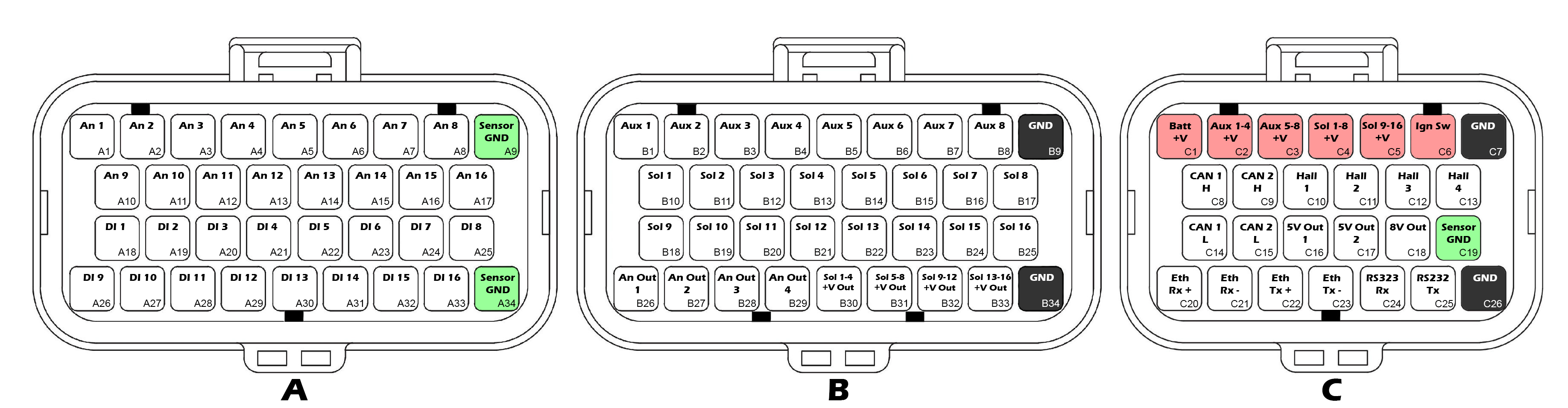
Looking into TCM
Connector A
InfoMating Connector: 4-1437290-0| Pin | Function |
|---|---|
| A1 | ANV 1 |
| A2 | ANV 2 |
| A3 | ANV 3 |
| A4 | ANV 4 |
| A5 | ANV 5 |
| A6 | ANV 6 |
| A7 | ANV 7 |
| A8 | ANV 8 |
| A9 | Sensor 0V Ref |
| A10 | ANV 9 |
| A11 | ANV 10 |
| A12 | ANV 11 |
| A13 | ANV 12 |
| A14 | ANV 13 |
| A15 | ANV 14 |
| A16 | ANV 15 |
| A17 | ANV 16 |
| A18 | DI 1 |
| A19 | DI 2 |
| A20 | DI 3 |
| A21 | DI 4 |
| A22 | DI 5 |
| A23 | DI 6 |
| A24 | DI 7 |
| A25 | DI 8 |
| A26 | DI 9 |
| A27 | DI 10 |
| A28 | DI 11 |
| A29 | DI 12 |
| A30 | DI 13 |
| A31 | DI 14 |
| A32 | DI 15 |
| A33 | DI 16 |
| A34 | Sensor 0V Ref |
Connector B
InfoMating Connector: 4-1437290-1| Pin | Function |
|---|---|
| B1 | Aux 1 |
| B2 | Aux 2 |
| B3 | Aux 3 |
| B4 | Aux 4 |
| B5 | Aux 5 |
| B6 | Aux 6 |
| B7 | Aux 7 |
| B8 | Aux 8 |
| B9 | GND |
| B10 | Solenoid 1 |
| B11 | Solenoid 2 |
| B12 | Solenoid 3 |
| B13 | Solenoid 4 |
| B14 | Solenoid 5 |
| B15 | Solenoid 6 |
| B16 | Solenoid 7 |
| B17 | Solenoid 8 |
| B18 | Solenoid 9 |
| B19 | Solenoid 10 |
| B20 | Solenoid 11 |
| B21 | Solenoid 12 |
| B22 | Solenoid 13 |
| B23 | Solenoid 14 |
| B24 | Solenoid 15 |
| B25 | Solenoid 16 |
| B26 | Analog Out 1 |
| B27 | Analog Out 2 |
| B28 | Analog Out 3 |
| B29 | Analog Out 4 |
| B30 | Solenoid 1-4 Supply Output |
| B31 | Solenoid 5-8 Supply Output |
| B32 | Solenoid 9-12 Supply Output |
| B33 | Solenoid 13-16 Supply Output |
| B34 | GND |
Connector C
InfoMating Connector: 3-1437290-7| Pin | Function |
|---|---|
| C1 | Battery Hot Supply |
| C2 | Aux 1-4 Supply |
| C3 | Aux 5-8 Supply |
| C4 | Solenoid 1-8 Supply |
| C5 | Solenoid 9-16 Supply |
| C6 | Ignition Switch |
| C7 | GND |
| C8 | CAN 1 Hi |
| C9 | CAN 2 Hi |
| C10 | Hall 1 |
| C11 | Hall 2 |
| C12 | Hall 3 |
| C13 | Hall 4 |
| C14 | CAN 1 Lo |
| C15 | CAN 2 Lo |
| C16 | 5V0 Ref Output 1 |
| C17 | 5V0 Ref Output 2 |
| C18 | 8V0 Ref Output |
| C19 | Sensor 0V Ref |
| C20 | Ethernet Rx+ |
| C21 | Ethernet Rx- |
| C22 | Ethernet Tx+ |
| C23 | Ethernet Tx- |
| C24 | RS232 Rx |
| C25 | RS232 Tx |
| C26 | GND |
Features
Power Supply
- Reverse polarity protection
- Over temperature protection
- Over current protection
- Current & voltage diagnostic monitoring
- 1x Battery constant supply
- 2x Auxiliary output driver supplies
- 2x Solenoid supplies
- 1x Ignition switch input
- 24V Compatible
Processor
- Dual Core, 650 MHz, 32bit Automotive Processor
- Xilinx 7 Series FPGA
- 512MB DDR3 RAM
Solenoid Outputs
16x Proportional Current Solenoid Drivers
- 0.1 – 20 KHz PWM
- Low side only
- 1.5A max current setpoint in single mode
- 2.7A max current setpoint in paired mode
- 1.8A continuous current per pin
- Current monitoring and control on all pins
- Current dither for reduced stiction and faster solenoid response
- Flywheel diodes connected to solenoid power supply outputs (see below)
- Unused solenoid outputs can be used as low side auxiliary outputs
Solenoid Power Supply Outputs x4
4x Protected Solenoid Supply Outputs
- Protected and monitored solenoid supply pins
- Over current protected
- Current & voltage diagnostic monitoring
Auxiliary Outputs
8x Auxiliary Outputs
- Half-Bridge Drivers
- 0.1 – 20 KHz PWM
- High Side / Low Side 35A peak, 8A continuous
- Bi-directional current monitoring on all pins
Analog Outputs
4x Analog Outputs
- 0-5V, 10 bit, 4.88 mV resolution
- 11 mA per channel
Analog Inputs
16x Analog Inputs
- 0-5V
- 12 bit, 1.22mV resolution
- Switchable 1K pullups to 5V Out 1 on pins 1-8
- Switchable 1K pullups to 5V Out 2 on pins 9-16
- 100K Ohms to ground
Digital Inputs
16x Digital Inputs
- 0.5 – 20KHz
- 0-39V Analog Input on all pins
- 12 bit, 9.52mV resolution
- Hall effect & Reluctor sensor compatible
- Switchable 4K7 pullup to 8.0V on all pins
- Switchable 330R pulldown to GND on pins 1-8
Digital Input 1-8:
- Programmable 0-5V high trigger threshold
- Programmable 0-5V low trigger threshold
Digital Input 9-16:
- Fixed high trigger threshold: 2.4V
- Fixed low trigger threshold: 0.5V
Hall Sensor Inputs
4x 2-Wire Hall Effect Sensor Inputs
- 0.5 – 20KHz
- Open circuit detection
- Short to Battery detection
- Short to Ground detection
Inertial Measurement Unit
- 3 Axis Accelerometer, ±2/4/8/16 g
- 3 Axis Gyroscope, ±125 - ±4000 dps
On board Sensors
- Barometric Pressure Sensor
- PCB Temperature Sensor
Communications
- 10/100 Ethernet PC tuning interface, high speed, high noise immunity
- 2x CAN 2.0A/B Interfaces, fully user configurable, selectable termination.
- 1x RS232 Serial Interface
Data Logging
- 8GB Onboard eMMC logging memory.
Programming
All device configuration and firmware updates are done via ethernet connection with our free TMtune PC Software.
TM16-R35 Adapter Datasheet
The TM16-R35 Adapter allows Plug-n-Play control of the Nissan GR6 DCT transmission in the 2007+ R35 GTR.
Pinout
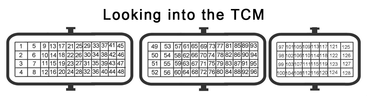
Connector A (Black)
| OEM Pin | Function | TM16 Pin |
|---|---|---|
| 1 | +14V (TCM Relay) | C2, C3, C4, C5 |
| 2 | - | |
| 3 | GND | B9, B34, C7, C26 |
| 4 | GND | B9, B34, C7, C26 |
| 5 | +14V (TCM Relay) | C2, C3, C4, C5 |
| 6 | - | |
| 7 | GND | B9, B34, C7, C26 |
| 8 | GND | B9, B34, C7, C26 |
| 9 | Batt +14V | C1 |
| 10 | Reverse Light Output | Sol 15 (B24) |
| 11 | CAN 1 H | C8 |
| 12 | - | |
| 13 | - | |
| 14 | TCM Power Relay | Sol 16 (B25) |
| 15 | CAN 1 L | C14 |
| 16 | Brake Switch 1 | DI 10 (A27) |
| 17 | Ignition Switch | C6 |
| 18 | - | |
| 19 | Starter Relay Enable | Aux 8 (B8) |
| 20 | - | |
| 21 | - | |
| 22 | - | |
| 23 | Manual Switch 1 | DI 7 (A24) |
| 24 | - | |
| 25 | 5V Ref 2 | C17 |
| 26 | 5V Ref 2 | C17 |
| 27 | Shifter Pos Switch 1 | ANV 9 (A10) |
| 28 | Manual Switch 2 | DI 8 (A25) |
| 29 | - | |
| 30 | - | |
| 31 | Engine Speed (Tracking) | DI 4 (A21) |
| 32 | - | |
| 33 | Shifter Pos Switch 2 | ANV 10 (A11) |
| 34 | Snow Mode Switch | DI 13 (A30) |
| 35 | Shifter Pos Switch 4 | ANV 12 (A13) |
| 36 | - | |
| 37 | R Mode Switch | DI 12 (A29) |
| 38 | Shifter Pos Switch 3 | ANV 11 (A12) |
| 39 | Up Shift Switch | DI 5 (A22) |
| 40 | - | |
| 41 | - | |
| 42 | Down Shift Switch | DI 6 (A23) |
| 43 | Shifter Pos Switch 5 | ANV 13 (A14) |
| 44 | Shifter Pos Switch 6 | ANV 14 (A15) |
| 45 | R Mode Lamp | Sol 13 (B22) |
| 46 | Shift Lock Solenoid | Aux 6 (B6) |
| 47 | Snow Mode Lamp | Sol 14 (B23) |
| 48 | - |
Connector B (Brown)
| OEM Pin | Function | TM16 Pin |
|---|---|---|
| 49 | Shift Solenoid 1 | Aux 1 (B1) |
| 50 | - | |
| 51 | Shift Solenoid 3 | Aux 3 (B3) |
| 52 | - | |
| 53 | Shift Solenoid 5 | Aux 5 (B5) |
| 54 | Shift Solenoid 2 | Aux 2 (B2) |
| 55 | - | |
| 56 | Shift Solenoid 4 | Aux 4 (B4) |
| 57 | Solenoid Supply | Sol 1-4 +V (B30) |
| 58 | - | |
| 59 | Solenoid Supply | Sol 5-8 +V (B31) |
| 60 | - | |
| 61 | - | |
| 62 | Axis A Solenoid | Sol 3 (B12) |
| 63 | - | |
| 64 | Axis B Solenoid | Sol 7 (B16) |
| 65 | - | |
| 66 | Sensor GND | A9, A34, C19 |
| 67 | Shift Fork 1 Pos (Main) | ANV 4 (A4) |
| 68 | Sensor GND | A9, A34, C19 |
| 69 | Sensor GND | A9, A34, C19 |
| 70 | Shift Fork 4 Pos (Main) | ANV 8 (A8) |
| 71 | 5V Ref 1 | C16 |
| 72 | Clutch A Speed | DI 1 (A18) |
| 73 | 5V Ref 1 | C16 |
| 74 | 5V Ref 1 | C16 |
| 75 | 5V Ref 1 | C16 |
| 76 | Speed Sensor + | (From TCM Relay) |
| 77 | Line Pressure Sensor | ANV 1 (A1) |
| 78 | Speed Sensor + | (From TCM Relay) |
| 79 | Shift Fork 1 Pos (Tracking) | ANV 5 (A5) |
| 80 | Sensor GND | A9, A34, C19 |
| 81 | 5V Ref 1 | C16 |
| 82 | Clutch B Speed | DI 2 (A19) |
| 83 | Sensor GND | A9, A34, C19 |
| 84 | Sensor GND | A9, A34, C19 |
| 85 | Shift Fork 2 Pos (Main) | ANV 6 (A6) |
| 86 | Sensor GND | A9, A34, C19 |
| 87 | Trans Fluid Temp | ANV 15 (A16) |
| 88 | 5V Ref 1 | C16 |
| 89 | Park Switch | DI 14 (A31) |
| 90 | - | |
| 91 | Sensor GND | A9, A34, C19 |
| 92 | Shift Fork 3 Pos (Main) | ANV 7 (A7) |
| 93 | - | |
| 94 | Sensor GND | A9, A34, C19 |
| 95 | - | |
| 96 | - |
Connector C (Grey)
| OEM Pin | Function | TM16 Pin |
|---|---|---|
| 97 | 5V Ref 1 | C16 |
| 98 | Clutch A Pressure | ANV 2 (A2) |
| 99 | Sensor GND | A9, A34, C19 |
| 100 | - | |
| 101 | - | |
| 102 | 5V Ref 1 | C16 |
| 103 | Clutch B Pressure | ANV 3 (A3) |
| 104 | Sensor GND | A9, A34, C19 |
| 105 | Speed Sensor + | (From TCM Relay) |
| 106 | Output Shaft Speed | DI 3 (A20) |
| 107 | Sensor GND | A9, A34, C19 |
| 108 | - | |
| 109 | - | |
| 110 | - | |
| 111 | - | |
| 112 | - | |
| 113 | Line Pressure Solenoid | Sol 9 (B18) |
| 114 | - | |
| 115 | Lubrication Flow Solenoid | Sol 11 (B20) |
| 116 | - | |
| 117 | - | |
| 118 | Solenoid Supply | Sol 9-12 +V (B32) |
| 119 | - | |
| 120 | Solenoid Supply | Sol 9-12 +V (B32) |
| 121 | Solenoid Supply | Sol 1-4 +V (B30) |
| 122 | - | |
| 123 | Solenoid Supply | Sol 5-8 +V (B31) |
| 124 | - | |
| 125 | - | |
| 126 | Clutch A Solenoid | Sol Pair 1&4 (B10+B13) |
| 127 | - | |
| 128 | Clutch B Solenoid | Sol Pair 5&8 (B14+B17) |
Changelog
Version 1.1 - 31/07/2026
Clutch solenoids now use Solenoid Pairs 1&4, 5&8 to allow more than 1.5A
The OEM solenoid current limit is 1.5A, which is also the setpoint limit of a single TM16 solenoid output. At 1.5A of current, the clutch will achieve approximately 17 Bar of clutch pressure. Solenoid outputs can be paired to achieve up to 2.7A (It’s unlikely that more than 2.0A is useful). Version 1.1 hardware supports the solenoid pairing.
The cal file should be updated to use the solenoid pairs in the output config.
Version 1.0 hardware can utilize the additional current by modifying the wiring to splice the TM16’s solenoid outputs 1&4 together, and 5&8 together.
Version 1.0 - 01/04/2026
Initial Release
Transmissions
Subsections of Transmissions
Getrag GS7
Beta Notice
The GS7 base cal file has been built using a dedicated track car as the test platform. While it is fully functional and drives very well, it may not be optimized in all aspects.
Wiring
The OEM Mechatronic unit must be removed so that the transmission can be run directly by the TCM.
The example below uses the DomiWorks Install Board.
The pullup resistors supplied on the board should be removed as pullup control is available on all TCM inputs where required.
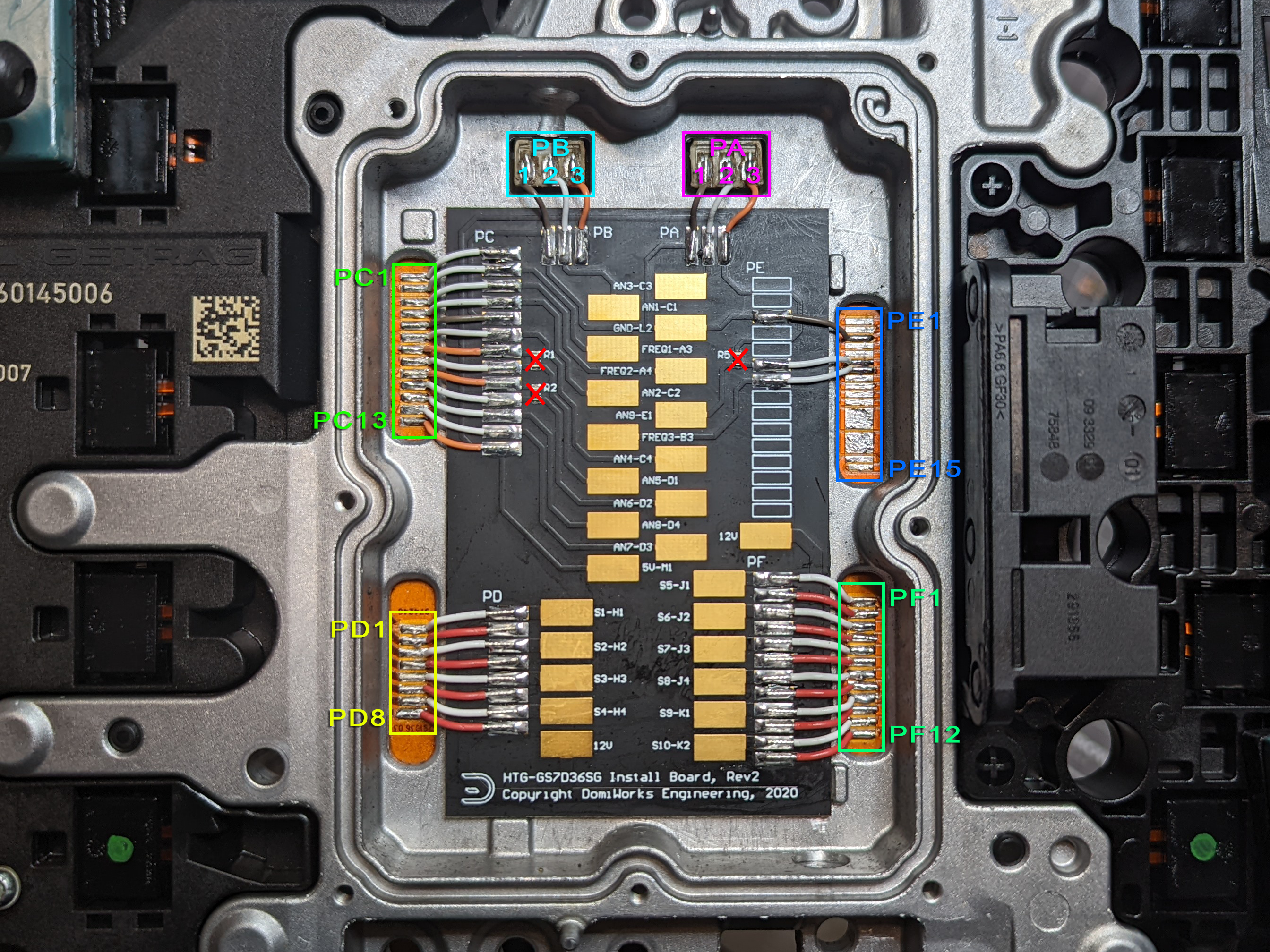
Pad Group A
| OEM Pad | Function | TCM Pin |
|---|---|---|
| PA1 | SGND | SGND |
| PA2 | Clutch A Pressure | An 3 |
| PA3 | +5V | 5V Out 1 |
Pad Group B
| OEM Pad | Function | TCM Pin |
|---|---|---|
| PB1 | SGND | SGND |
| PB2 | Clutch B Pressure | An 1 |
| PB3 | +5V | 5V Out 1 |
Pad Group C
| OEM Pad | Function | TCM Pin |
|---|---|---|
| PC1 | ||
| PC2 | Clutch A Speed | Hall 1 |
| PC3 | Clutch B Speed | Hall 2 |
| PC4 | Fork 4/6 Position | An 2 |
| PC5 | SGND | SGND |
| PC6 | Fork 5/7 Position | An 4 |
| PC7 | +5V | 5V Out 1 |
| PC8 | Clutch A Temp (NC, marked “redundant” in OEM docs) | An 5 |
| PC9 | +5V | 5V Out 1 |
| PC10 | Clutch B Temp (NC, marked “redundant” in OEM docs) | An 6 |
| PC11 | Fork 2/R Position | An 8 |
| PC12 | Fork 1/3 Position | An 7 |
| PC13 | +5V | 5V Out 1 |
Pad Group D
| OEM Pad | Function | TCM Pin |
|---|---|---|
| PD1 | Shift Solenoid 1 | Sol 13 |
| PD2 | Solenoid +12V | Sol +V Out (B33) |
| PD3 | Shift Solenoid 2 | Sol 14 |
| PD4 | Solenoid +12V | Sol +V Out (B33) |
| PD5 | Shift Solenoid 3 | Sol 15 |
| PD6 | Solenoid +12V | Sol +V Out (B33) |
| PD7 | Shift Solenoid 4 | Sol 16 |
| PD8 | Solenoid +12V | Sol +V Out (B33) |
Pad Group E
| OEM Pad | Function | TCM Pin |
|---|---|---|
| PE1 | ||
| PE2 | ||
| PE3 | SGND | SGND |
| PE4 | ||
| PE5 | ||
| PE6 | Trans Fluid Temp | An 9 |
| PE7 | Input Shaft Speed | Hall 3 |
| PE8 | ||
| PE9 | ||
| PE10 | ||
| PE12 | ||
| PE13 | ||
| PE14 | ||
| PE15 |
Pad Group F
| OEM Pad | Function | TCM Pin |
|---|---|---|
| PF1 | Axis A Safety | Sol 2 |
| PF2 | Solenoid + 12V | Sol +V Out (B30) |
| PF3 | Clutch A | Sol Pair 1 & 4 |
| PF4 | Solenoid + 12V | Sol +V Out (B30) |
| PF5 | Axis B Safety | Sol 6 |
| PF6 | Solenoid + 12V | Sol +V Out (B30) |
| PF7 | Clutch B | Sol Pair 5 & 8 |
| PF8 | Solenoid + 12V | Sol +V Out (B30) |
| PF9 | Line Pressure Solenoid | Sol 9 |
| PF10 | Solenoid + 12V | Sol +V Out (B30) |
| PF11 | Cooling Flow Solenoid | Sol 10 |
| PF12 | Solenoid + 12V | Sol +V Out (B30) |
Gear Ratios
Short Ratio
| Gear | Ratio |
|---|---|
| R | -3.667 |
| 1st | 4.780 |
| 2nd | 2.933 |
| 3rd | 2.153 |
| 4th | 1.678 |
| 5th | 1.390 |
| 6th | 1.203 |
| 7th | 1.000 |
Clutch Geometry
| Clutch | Plates (S/D) | Friction ID/OD (mm) | Piston ID/OD (mm) |
|---|---|---|---|
| Clutch A | 2(S) + 4(D) | 190.0 / 218.0 | 190.0 / 208.0 * |
| Clutch B | 2(S) + 4(D) | 121.5 / 162.0 | 96.0 / 140.0 * |
* Piston diameters are close approximations only
Note
Our test vehicle was a track car with unknown clutch condition. We settled on a Estimated Clutch Efficiency factor of 65% but can’t say for certain if this is correct for all installations.
Shift Forks
The GS7 has 4 shift forks controlled by 4 Shift Solenoids. Operation is fairly simple, with a binary combination of solenoids resulting in a different movement operation.
Manipulating the current through the shift solenoid allows the fork movement to be slowed as it approaches the target.
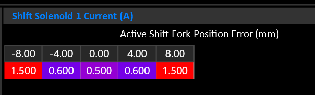
Selector Forks
| Fork | Gear Low | Gear High |
|---|---|---|
| 1 | 4 | 6 |
| 2 | 2 | R |
| 3 | 1 | 3 |
| 4 | 5 | 7 |
Reverse and 2nd are on different clutches.
Fork 2 must be assigned to Axis A & B to inform the system that this is not a config mistake.
Gear to Fork Mapping
The following table shows the nominal fork mapping. Actual positions should be fine tuned with real world measurements see during operation.
| Gear | Fork | Position | Volts |
|---|---|---|---|
| R | 2-H | 8.0mm | 3.830 |
| N | ALL | 0.0mm | 2.500 |
| 1 | 3-L | -8.0mm | 1.360 |
| 2 | 2-H | -8.0mm | 1.360 |
| 3 | 3-H | 8.0mm | 3.830 |
| 4 | 1-L | 8.0mm | 3.830 |
| 5 | 3-H | 8.0mm | 1.360 |
| 6 | 1-H | -8.0mm | 1.360 |
Shift Solenoids
| Solenoid | Function |
|---|---|
| 1 | Fork Move +/- |
| 2 | Fork Move +/- |
| 3 | Fork Select B0 |
| 4 | Fork Select B1 |
Shift Solenoid Truth Table
| Fork | Gear | Sol 1 | Sol 2 | Sol 3 | Sol 4 |
|---|---|---|---|---|---|
| 1 (4/6) | 4 « | X | X | ||
| 1 (4/6) | » 6 | X | X | ||
| 2 (2/R) | R « | X | |||
| 2 (2/R) | » 2 | X | |||
| 3 (1/3) | 1 « | X | X | ||
| 3 (1/3) | » 3 | X | X | ||
| 4 (5/7) | 5 « | X | X | X | |
| 4 (5/7) | » 7 | X | X | X |
Line Pressure
The line pressure solenoid reduces line pressure as current increases. Maximum line pressure is achieved when the solenoid is completely off.
No line pressure sensor is available.
Clutch Pressure
Clutch pressure is controlled by a solenoid for each clutch. To achieve maximum pressure they must be driven to approximately 1.8-1.9 Amps. To do so, the solenoids need to be wired to a Solenoid Pair so that more than 1.5A can be targeted.
- Each clutch has a pressure sensor.
- Each clutch/axis has a safety solenoid that must be energized to allow clutch pressure to be applied.
Input Shaft Speed
An Input Shaft Speed sensor is available. This effectively measures engine RPM as it’s the speed BEFORE the input to the clutch baskets.
The sensor is 2 wire hall effect type. Use Hall Input 1-4.
Clutch Speeds
Each Clutch has an output speed sensor. The sensor measures the speed of the output side of the clutch basket. This speed varies depending on the selected gear.
Slip is calculated based on the difference between Input Shaft Speed and Clutch A/B Speed.
The sensors are 2 wire hall effect type. Use Hall Input 1-4.
Output Shaft Speed
The GS7 does not have an output shaft speed sensor. Instead, leave the Output Shaft Speed input OFF and the TCM will calculate Output Shaft Speed using the active clutch and it’s currently selected gear.
Lubrication / Cooling Flow
The GS7 has a solenoid dedicated to cooling the clutches.
Nissan GR6
Wiring
Refer to the Emtron TM16-R35 Adapter Kit Datasheet.
Gear Ratios
| Gear | Ratio |
|---|---|
| R | -3.383 |
| 1st | 4.056 |
| 2nd | 2.301 |
| 3rd | 1.595 |
| 4th | 1.248 |
| 5th | 1.001 |
| 6th | 0.796 |
| FD | 3.700 |
Shift Forks
| Fork | Gear Low | Gear High |
|---|---|---|
| 1 | R | 1 |
| 2 | 2 | 4 |
| 3 | 3 | 5 |
| 4 | 6 | - |
Gear to Fork Mapping
| Gear | Fork | Position | Volts |
|---|---|---|---|
| R | 1-L | -9.0mm | 1.300 / 3.800* |
| N | ALL | 0.0mm | 2.500 |
| 1 | 1-H | 9.0mm | 3.800 / 1.300* |
| 2 | 2-L | 9.0mm | 1.300 |
| 3 | 3-L | 9.0mm | 1.300 |
| 4 | 2-H | -9.0mm | 3.800 |
| 5 | 3-H | -9.0mm | 3.800 |
| 6 | 4-L | 9.0mm | 1.300 |
* Fork 1 has two position sensors.
Shift Solenoids
| Solenoid | Function |
|---|---|
| 1 | 4 / N |
| 2 | 2 / 6 |
| 3 | R / 5 |
| 4 | 1 / 3 |
| 5 | Fork 3 & 4 Select |
Shift Solenoid Truth Table
| Fork | Gear | Sol 1 | Sol 2 | Sol 3 | Sol 4 | Sol 5 |
|---|---|---|---|---|---|---|
| 1 (1/R) | R « | X | ||||
| 1 (1/R) | » 1 | X | ||||
| 2 (2/4) | 2 « | X | ||||
| 2 (2/4) | » 4 | X | ||||
| 3 (3/5) | 3 « | X | X | |||
| 3 (3/5) | » 5 | X | X | |||
| 4 (6/N) | 6 « | X | X | |||
| 4 (6/N) | » N | X | X |
Axis Feed Pressure Solenoids
Active Axis/Clutch Behavior
Maintains about 3.5 bar above the active clutch pressure target.
Inactive Axis/Clutch Behavior
Holds 10 bar at most times. During fork movement, the inactive axis pressure is used to control the shift fork movement force and velocity. Once the fork is in position it returns to 10 bar.
Lubricating Flow Solenoid
Remains active by default, allowing fully lubrication and cooling flow. During a shift or high torque demand it will close off, to reduce pressure drop and allow maximum line pressure availability.
Known Issues / Limitations
Start Button Hold to Start
The R35 TCM is responsible for determining that the engine is safe to crank and supplies the positive side of the starter relay with power when the transmission is in Park or Neutral. The window of time for this to happen when the start button is held from fully off, with brake applied, is only a couple of hundred milliseconds. The TM16’s boot up process takes slightly longer than the factory TCM because it runs a very complex CPU & FPGA. As a result, the starter relay receives power too late. The starter solenoid will click but the BCM will have already given up. The R35 base cal has a deliberate delay added to the user function that drives the starter relay power so that the one shot hold to start does not work at all. Instead the ignition will turn on normally, and the engine will start with a second press of the start button.
Hill Hold
The OEM hill hold function that tells the ABS module to lock the brakes on a hill is not currently supported. We intend to add support for this function in a future update.
Limp Home Skip Shifting
When an axis/clutch detects an error the OEM TCM will lockout the problem axis and skip shift (eg 2 to 4 to 6, ignoring 1,3,5 or visa versa). Current firmware does not support this function. Full fault detection is implemented and every shift fork is monitored for correct positioning at all times including before a shift can occur. In the event of a fault (such as a fork being stuck in the wrong position), rather than skip shift, the transmission will remain in whatever gear is currently driving. Full limp home skip shifting is planned for a future update.
ZF 8HP
Models
Caution
Currently, only 8HP models with 16 pin connectors are compatible. Models with only 10 pins do not have the required IO to allow an external TCM.
| Model | Support | Comment |
|---|---|---|
| 8HP45 | Y | Gen 1 |
| 8HP50 | Y | Gen 2 |
| 8HP51 | N* | Gen 3 *Requires Gen 2 valve body |
| 8HP70 | Y | Gen 1 |
| 8HP75 | Y | Gen 2 |
| 8HP76 | N* | Gen 3 *Requires Gen 2 valve body |
| 8HP90 | Y | Gen 1 |
| 8HP95 | Y | Gen 2 |
Base Calibration
A base calibration based on the 8HP70 is included with TMtune. Solenoid pressure translation tables are also included separately.
Wiring
Mechatronics Modifications
In order to control the 8HP transmission, the internal mechatronics unit must be bypassed and the control signals routed externally.
- Remove the mechatronics assembly from the transmission.
- Cut the lid off the OEM TCM enclosure.
- Cut all the fine wire connections between the OEM TCM and the interface pads.
- Wire connections between pads as follows…
Caution
22 AWG or 24 AWG Tefzel wire should be used to bridge connections as it can withstand the temperatures and oil present inside the transmission.
For simplicity and compatibility we’re using the same pin designations as the DomiWorks 8HP Wiring Kit.
| IO Pin (A) | Internal Pin (B/C) |
|---|---|
| A1 | C2 |
| A2 | C3 |
| A3 | C4 |
| A4 | C16 |
| A5 | C13 |
| A6 | C14 |
| A7 | B2 |
| A8 | B3 |
| A9 | B4 |
| A10 | B5 |
| A11 | B6 |
| A12 | B10, B11, B12, B13 |
| A13 | B10, B11, B12, B13 |
| A14 | C12 |
| A15 | C12 |
| A16 | B7 |
| A17 | B8 |
| A18 | B9 |
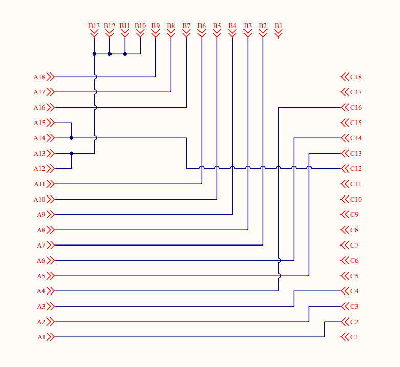
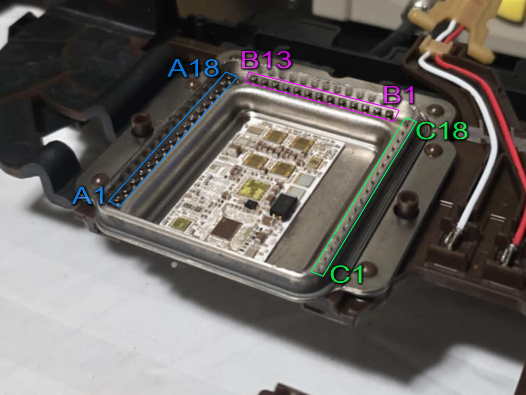
Potting
We have found that potting the modified mechatronics units with compounds such as R125 has resulted in repeated failures. There appears to be a negative interaction between R125 and the oil used in the 8HP transmissions. The most reliable results we have seen have come from NOT potting the internal connections.
Gearbox Connector
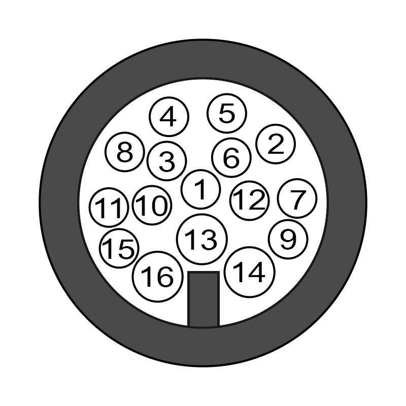
Important
Pinout assumes mechatronic modifications have been completed as detailed above.
| Pin | Function | TCM Pin *1 |
|---|---|---|
| 1 | Sensor 0V Ref | Sensor GND (A9) |
| 2 | Line Pressure Solenoid | Sol 6 (B15) |
| 3 | Speed Sensor 8V Supply | 8V Out (C18) |
| 4 | Accumulator Solenoid | Sol 10 (B19) |
| 5 | Park Hold Solenoid | Sol 9 (B18) |
| 6 | Park Release Solenoid | Sol 8 (B17) |
| 7 | Clutch C Solenoid | Sol 3 (B12) |
| 8 | Input Shaft Speed Signal | DI 1 (A18) |
| 9 | Clutch E Solenoid | Sol 5 (B14) |
| 10 | Output Shaft Speed Signal | DI 2 (A19) |
| 11 | Brake A Solenoid | Sol 1 (B10) |
| 12 | TC Lockup Solenoid | Sol 7 (B16) |
| 13 | Trans Fluid Temp Sensor | An 1 (A1) |
| 14 | Solenoid Power Supply | Sol +V Out (B30+B31) *2 |
| 15 (Gen 1) | Clutch D Solenoid | Sol 4 (B13) *3 |
| 15 (Gen 2) | Brake B Solenoid | Sol 4 (B13) *3 |
| 16 (Gen 1) | Brake B Solenoid | Sol 2 (B11) *3 |
| 17 (Gen 2) | Clutch D Solenoid | Sol 2 (B11) *3 |
1. This pinout matches the supplied 8HP base calibration. You’re free to alter the TCM pin assignments as long as the change is reflected in the config.
2. Ideally each 4 solenoids would have a separate supply bank, but this isn’t possible using the OEM connector. Connecting to two bridged solenoid supplies will suffice.
3. To cater for Gen 1 vs Gen 2, swap the Brake B / Clutch D solenoid assignment in config OR swap pins 15 / 16 in the wiring harness.
Speed Sensors
- Input Shaft Speed
- Output Shaft Speed
The sensors are 2-wire hall effect type, however the polarity of the internal wiring means the dedicated hall sensor inputs on the TCM cannot be used. Instead, the sensors can be wired to Digital Inputs 1 to 8. The internal 330R pulldown must to be enabled.
In this arrangement, the signal voltage will sit at around 2V when stationary, and pulse up to around 4V when a tooth passes the sensor.
The high and low arming thresholds must be set correctly to detect the speed signal. The low threshold must be ABOVE the sensor voltage at rest, and the high threshold must be BELOW the maximum voltage when the sensor is active.
Speed Sensor Calibration
| Model | Input Shaft Speed | Output Shaft Speed |
|---|---|---|
| 8HP50 | 28 Teeth | 40 Teeth |
| 8HP70 | 30 Teeth | 40 Teeth |
Solenoids
The ZF 8HP contains nine solenoids. All but the park-release/hold solenoids are Variable‐Force Solenoids (VSF). The park‐release and park‐hold are on/off.
Shift Elements
The 8HP uses the following “shift elements”:
- Two fixed multidisc brakes (brake A and B)
- Three rotary multidisc clutches (clutch C, D and E).
The multidisc clutches (C, D and E) feed the drive torque to the planetary gear. The multidisc brakes (A and B) support the torque against the transmission housing.
| Solenoid | Shift Element | Note |
|---|---|---|
| Clutch Solenoid A | Brake A | VFS, normally vented (no pressure when off). |
| Clutch Solenoid B | Brake B | VFS, normally vented (no pressure when off). |
| Clutch Solenoid C | Clutch C | VFS, normally applied (high pressure when off). |
| Clutch Solenoid D | Clutch D | VFS, normally applied (high pressure when off). |
| Clutch Solenoid E | Clutch E | VFS, normally applied (high pressure when off). |
Line Pressure Solenoid
VFS, normally applied. Modulates the valve-body pressure regulator to maintain the transmission’s main hydraulic (line) pressure under all operating conditions.
Torque Converter Clutch (TCC) Solenoid
VFS, normally vented. Controls apply pressure to the lock-up piston in the torque converter for smooth lock/unlock transitions.
Park Release Solenoid
On/Off, normally open. When energized, it directs line pressure to the park-release valve to retract the parking pawl, allowing selection of Drive or Reverse.
Park Hold Solenoid
Mechanical. Clips onto and holds the park-release piston in its disengaged position after the pawl is withdrawn. Does not flow hydraulic oil.
Clutch Geometry
The following data is provided as a guide based on the best information available at time of writing.
8HP70
| Clutch | Plates (S/D) | Friction ID/OD (mm) | Piston ID/OD (mm) |
|---|---|---|---|
| Brake A | 5 (D) | 126.0 / 144.0 | 99.5 / 144.1 |
| Brake B | 5 (D) | 176.0 / 196.0 | 168.9 / 206.5 |
| Clutch C | 6 (D) | 139.0 / 163.0 | 44.8 / 95.7 |
| Clutch D | 4 (D) | 149.0 / 172.0 | 47.5 / 126.7 |
| Clutch E | 5 (D) | 139.0 / 163.0 | 46.0 / 116.0 |
Gear Sequencing
By engaging different combinations of the five shift elements listed above, the transmission obtains each of its eight forward ratios (plus reverse).
| Gear | Brake A | Brake B | Clutch C | Clutch D | Clutch E |
|---|---|---|---|---|---|
| P | |||||
| R | X | X | X | ||
| N | |||||
| 1 | X | X | X | ||
| 2 | X | X | X | ||
| 3 | X | X | X | ||
| 4 | X | X | X | ||
| 5 | X | X | X | ||
| 6 | X | X | X | ||
| 7 | X | X | X | ||
| 8 | X | X | X |
Clutch Gear Load Factor
The ratio of input torque that each clutch/brake element carries for a given gear.
| Gear | Brake A | Brake B | Clutch C | Clutch D | Clutch E |
|---|---|---|---|---|---|
| R | 0.333 | 2.594 | - | 3.296 | - |
| N | - | - | — | - | - |
| 1 | 0.333 | 3.695 | 1.000 | - | - |
| 2 | 0.333 | 2.463 | - | - | 0.667 |
| 3 | - | 1.103 | 1.000 | - | 1.000 |
| 4 | - | 1.111 | - | 1.666 | 1.000 |
| 5 | - | 0.673 | 1.000 | 1.284 | - |
| 6 | - | - | 1.000 | 1.000 | 1.000 |
| 7 | 0.220 | - | 1.000 | 1.739 | - |
| 8 | 0.222 | - | - | 0.666 | 0.666 |
Pressure Control
The 8HP does not have any pressure sensors. This means that all internal pressures are inferred from solenoid current. Because the TCM uses pressure targets it’s important to get the solenoid pressure translations as accurate as possible. The supplied 8HP base calibration includes pressure translation tables taken from OEM roms. In most cases these do not need to be changed.
Optionally, you may enable Line Pressure and/or Clutch Pressure estimations to give feedback based on actual solenoid activity and fluid temperature.
OEM
Subsections of OEM
BMW F-Series Shifter
F-Series shifter integration is available in firmware v0.35.0 or above.
Wiring
| Pin | Function |
|---|---|
| 1 | - |
| 2 | - |
| 3 | CAN 1 L |
| 4 | CAN 1 H |
| 5 | CAN 2 L (NC) |
| 6 | CAN 2 H (NC) |
| 7 | Ignition Switch +12V |
| 8 | GND |
| 9 | - |
| 10 | Battery +12V |
Only CAN 1 is required.
CAN Configuration
Important
The shifter operates at a CAN bitrate of 500K. All devices on the bus must operate at the same speed.
Enable the shifter by setting an available CAN Channel mode to BMW F-Seres Shifter.
Switch Inputs
The F-Series shifter will appear to the TCM as a collection of individual switches rather than a Shifter Position Input.
Each of the following switch inputs must have their input source set to CAN (Preset).
| Switch | Note |
|---|---|
| Park Request Switch | Button at top of shifter. Available from Neutral or Reverse. Unlock button on RHS required to exit Park. |
| Reverse Request Switch | Active when pushed fully forward (2 notches) from Neutral. Unlock button on RHS required. |
| Neutral Request Switch | Active when pushed forward while from Drive or pulled backward from reverse. |
| Drive Mode Switch | Active when pulled backward from Neutral, or fully backward (2 notches) from Park with Unlock button. |
| Manual Override Switch | Active when shifter is pushed left into M/S position. Must be in Drive first. |
| Up Shift Switch | Active when pulled backwards from left M/S position |
| Down Shift Switch | Active when pushed forwards from left M/S position |
Info
If Drive/Manual is exited while the shifter is in the left M/S position, the shifter will move itself back to the centre rest position.
Backlight Brightness
The brightness of the shifter’s illumination backlight is controlled by the CAN Shifter Brightness table found under OEM Functions.
TMtune Release Notes
Loading release notes…