Getrag GS7
Beta Notice
The GS7 base cal file has been built using a dedicated track car as the test platform. While it is fully functional and drives very well, it may not be optimized in all aspects.
Wiring
The OEM Mechatronic unit must be removed so that the transmission can be run directly by the TCM.
The example below uses the DomiWorks Install Board.
The pullup resistors supplied on the board should be removed as pullup control is available on all TCM inputs where required.
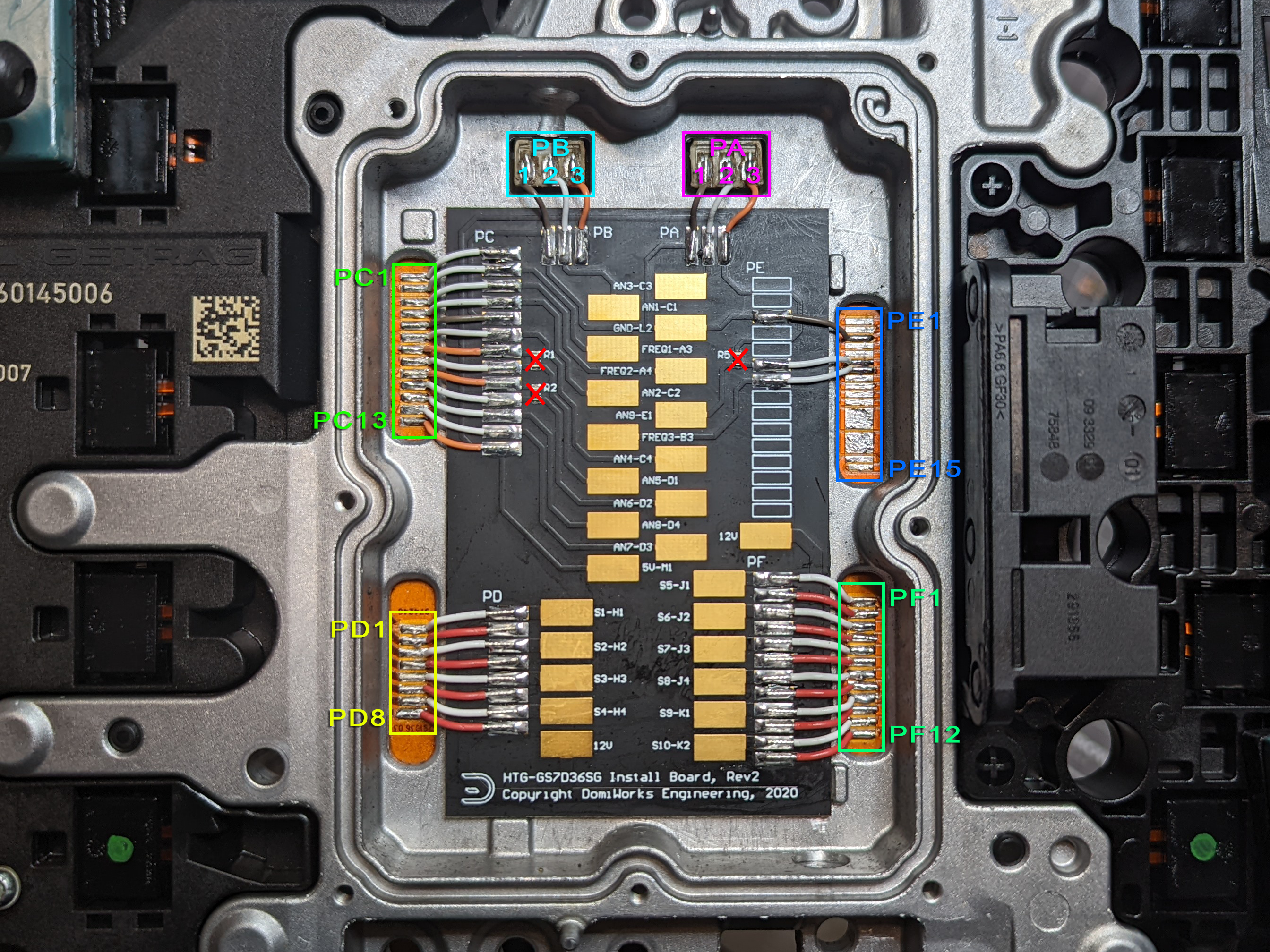
Pad Group A
| OEM Pad | Function | TCM Pin |
|---|---|---|
| PA1 | SGND | SGND |
| PA2 | Clutch A Pressure | An 3 |
| PA3 | +5V | 5V Out 1 |
Pad Group B
| OEM Pad | Function | TCM Pin |
|---|---|---|
| PB1 | SGND | SGND |
| PB2 | Clutch B Pressure | An 1 |
| PB3 | +5V | 5V Out 1 |
Pad Group C
| OEM Pad | Function | TCM Pin |
|---|---|---|
| PC1 | ||
| PC2 | Clutch A Speed | Hall 1 |
| PC3 | Clutch B Speed | Hall 2 |
| PC4 | Fork 4/6 Position | An 2 |
| PC5 | SGND | SGND |
| PC6 | Fork 5/7 Position | An 4 |
| PC7 | +5V | 5V Out 1 |
| PC8 | Clutch A Temp (NC, marked “redundant” in OEM docs) | An 5 |
| PC9 | +5V | 5V Out 1 |
| PC10 | Clutch B Temp (NC, marked “redundant” in OEM docs) | An 6 |
| PC11 | Fork 2/R Position | An 8 |
| PC12 | Fork 1/3 Position | An 7 |
| PC13 | +5V | 5V Out 1 |
Pad Group D
| OEM Pad | Function | TCM Pin |
|---|---|---|
| PD1 | Shift Solenoid 1 | Sol 13 |
| PD2 | Solenoid +12V | Sol +V Out (B33) |
| PD3 | Shift Solenoid 2 | Sol 14 |
| PD4 | Solenoid +12V | Sol +V Out (B33) |
| PD5 | Shift Solenoid 3 | Sol 15 |
| PD6 | Solenoid +12V | Sol +V Out (B33) |
| PD7 | Shift Solenoid 4 | Sol 16 |
| PD8 | Solenoid +12V | Sol +V Out (B33) |
Pad Group E
| OEM Pad | Function | TCM Pin |
|---|---|---|
| PE1 | ||
| PE2 | ||
| PE3 | SGND | SGND |
| PE4 | ||
| PE5 | ||
| PE6 | Trans Fluid Temp | An 9 |
| PE7 | Input Shaft Speed | Hall 3 |
| PE8 | ||
| PE9 | ||
| PE10 | ||
| PE12 | ||
| PE13 | ||
| PE14 | ||
| PE15 |
Pad Group F
| OEM Pad | Function | TCM Pin |
|---|---|---|
| PF1 | Axis A Safety | Sol 2 |
| PF2 | Solenoid + 12V | Sol +V Out (B30) |
| PF3 | Clutch A | Sol Pair 1 & 4 |
| PF4 | Solenoid + 12V | Sol +V Out (B30) |
| PF5 | Axis B Safety | Sol 6 |
| PF6 | Solenoid + 12V | Sol +V Out (B30) |
| PF7 | Clutch B | Sol Pair 5 & 8 |
| PF8 | Solenoid + 12V | Sol +V Out (B30) |
| PF9 | Line Pressure Solenoid | Sol 9 |
| PF10 | Solenoid + 12V | Sol +V Out (B30) |
| PF11 | Cooling Flow Solenoid | Sol 10 |
| PF12 | Solenoid + 12V | Sol +V Out (B30) |
Gear Ratios
Short Ratio
| Gear | Ratio |
|---|---|
| R | -3.667 |
| 1st | 4.780 |
| 2nd | 2.933 |
| 3rd | 2.153 |
| 4th | 1.678 |
| 5th | 1.390 |
| 6th | 1.203 |
| 7th | 1.000 |
Clutch Geometry
| Clutch | Plates (S/D) | Friction ID/OD (mm) | Piston ID/OD (mm) |
|---|---|---|---|
| Clutch A | 2(S) + 4(D) | 190.0 / 218.0 | 190.0 / 208.0 * |
| Clutch B | 2(S) + 4(D) | 121.5 / 162.0 | 96.0 / 140.0 * |
* Piston diameters are close approximations only
Note
Our test vehicle was a track car with unknown clutch condition. We settled on a Estimated Clutch Efficiency factor of 65% but can’t say for certain if this is correct for all installations.
Shift Forks
The GS7 has 4 shift forks controlled by 4 Shift Solenoids. Operation is fairly simple, with a binary combination of solenoids resulting in a different movement operation.
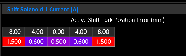
Manipulating the current through the shift solenoid allows the fork movement to be slowed as it approaches the target.
Selector Forks
| Fork | Gear Low | Gear High |
|---|---|---|
| 1 | 4 | 6 |
| 2 | 2 | R |
| 3 | 1 | 3 |
| 4 | 5 | 7 |
Reverse and 2nd are on different clutches.
Fork 2 must be assigned to Axis A & B to inform the system that this is not a config mistake.
Gear to Fork Mapping
The following table shows the nominal fork mapping. Actual positions should be fine tuned with real world measurements see during operation.
| Gear | Fork | Position | Volts |
|---|---|---|---|
| R | 2-H | 8.0mm | 3.830 |
| N | ALL | 0.0mm | 2.500 |
| 1 | 3-L | -8.0mm | 1.360 |
| 2 | 2-H | -8.0mm | 1.360 |
| 3 | 3-H | 8.0mm | 3.830 |
| 4 | 1-L | 8.0mm | 3.830 |
| 5 | 3-H | 8.0mm | 1.360 |
| 6 | 1-H | -8.0mm | 1.360 |
Shift Solenoids
| Solenoid | Function |
|---|---|
| 1 | Fork Move +/- |
| 2 | Fork Move +/- |
| 3 | Fork Select B0 |
| 4 | Fork Select B1 |
Shift Solenoid Truth Table
| Fork | Gear | Sol 1 | Sol 2 | Sol 3 | Sol 4 |
|---|---|---|---|---|---|
| 1 (4/6) | 4 « | X | X | ||
| 1 (4/6) | » 6 | X | X | ||
| 2 (2/R) | R « | X | |||
| 2 (2/R) | » 2 | X | |||
| 3 (1/3) | 1 « | X | X | ||
| 3 (1/3) | » 3 | X | X | ||
| 4 (5/7) | 5 « | X | X | X | |
| 4 (5/7) | » 7 | X | X | X |
Line Pressure
The line pressure solenoid reduces line pressure as current increases. Maximum line pressure is achieved when the solenoid is completely off.
No line pressure sensor is available.
Clutch Pressure
Clutch pressure is controlled by a solenoid for each clutch. To achieve maximum pressure they must be driven to approximately 1.8-1.9 Amps. To do so, the solenoids need to be wired to a Solenoid Pair so that more than 1.5A can be targeted.
- Each clutch has a pressure sensor.
- Each clutch/axis has a safety solenoid that must be energized to allow clutch pressure to be applied.
Input Shaft Speed
An Input Shaft Speed sensor is available. This effectively measures engine RPM as it’s the speed BEFORE the input to the clutch baskets.
The sensor is 2 wire hall effect type. Use Hall Input 1-4.
Clutch Speeds
Each Clutch has an output speed sensor. The sensor measures the speed of the output side of the clutch basket. This speed varies depending on the selected gear.
Slip is calculated based on the difference between Input Shaft Speed and Clutch A/B Speed.
The sensors are 2 wire hall effect type. Use Hall Input 1-4.
Output Shaft Speed
The GS7 does not have an output shaft speed sensor. Instead, leave the Output Shaft Speed input OFF and the TCM will calculate Output Shaft Speed using the active clutch and it’s currently selected gear.
Lubrication / Cooling Flow
The GS7 has a solenoid dedicated to cooling the clutches.