Subsections of Transmissions
Getrag GS7
Beta Notice
The GS7 base cal file has been built using a dedicated track car as the test platform. While it is fully functional and drives very well, it may not be optimized in all aspects.
Wiring
The OEM Mechatronic unit must be removed so that the transmission can be run directly by the TCM.
The example below uses the DomiWorks Install Board.
The pullup resistors supplied on the board should be removed as pullup control is available on all TCM inputs where required.
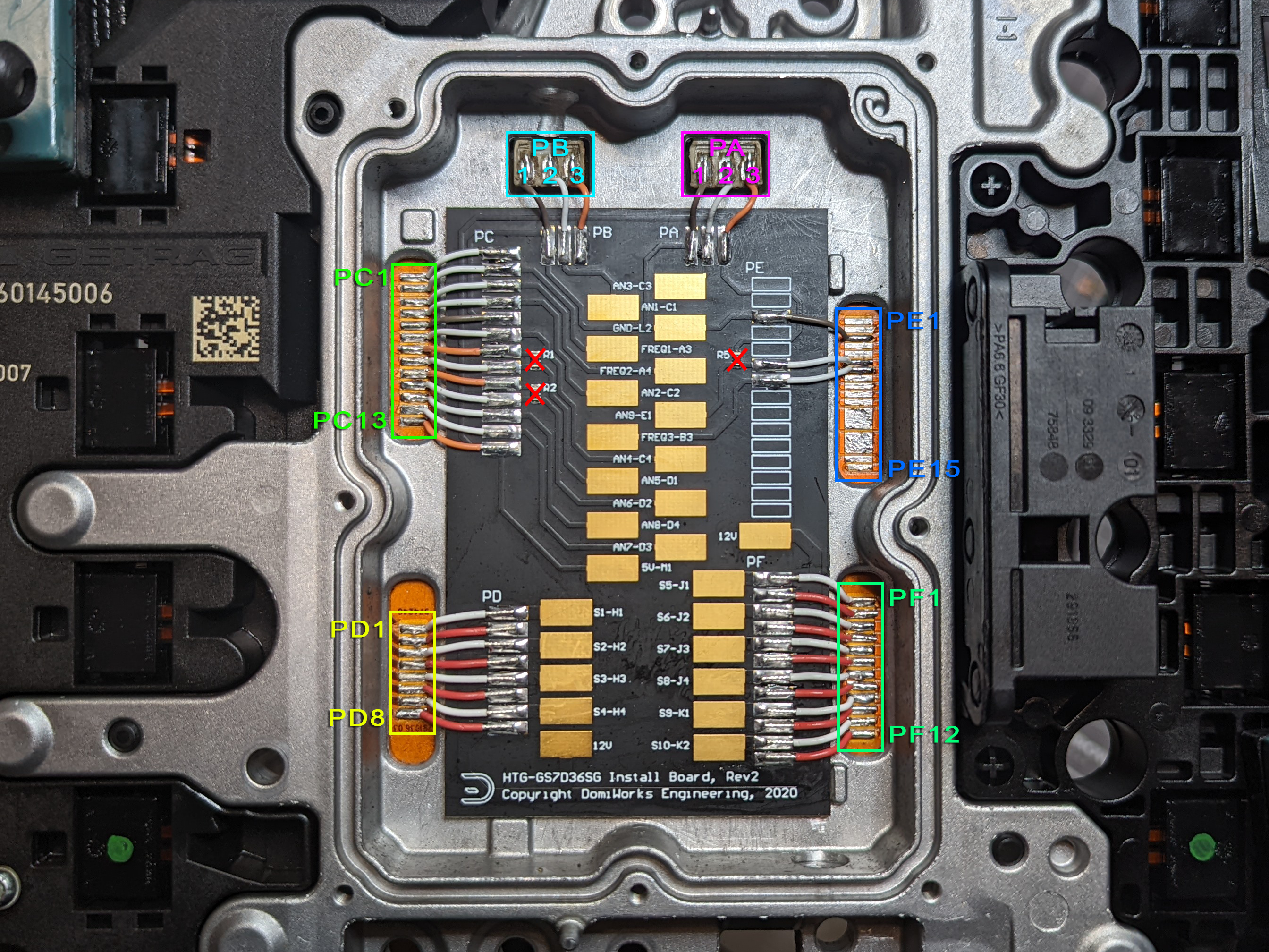
Pad Group A
| OEM Pad | Function | TCM Pin |
|---|---|---|
| PA1 | SGND | SGND |
| PA2 | Clutch A Pressure | An 3 |
| PA3 | +5V | 5V Out 1 |
Pad Group B
| OEM Pad | Function | TCM Pin |
|---|---|---|
| PB1 | SGND | SGND |
| PB2 | Clutch B Pressure | An 1 |
| PB3 | +5V | 5V Out 1 |
Pad Group C
| OEM Pad | Function | TCM Pin |
|---|---|---|
| PC1 | ||
| PC2 | Clutch A Speed | Hall 1 |
| PC3 | Clutch B Speed | Hall 2 |
| PC4 | Fork 4/6 Position | An 2 |
| PC5 | SGND | SGND |
| PC6 | Fork 5/7 Position | An 4 |
| PC7 | +5V | 5V Out 1 |
| PC8 | Clutch A Temp (NC, marked “redundant” in OEM docs) | An 5 |
| PC9 | +5V | 5V Out 1 |
| PC10 | Clutch B Temp (NC, marked “redundant” in OEM docs) | An 6 |
| PC11 | Fork 2/R Position | An 8 |
| PC12 | Fork 1/3 Position | An 7 |
| PC13 | +5V | 5V Out 1 |
Pad Group D
| OEM Pad | Function | TCM Pin |
|---|---|---|
| PD1 | Shift Solenoid 1 | Sol 13 |
| PD2 | Solenoid +12V | Sol +V Out (B33) |
| PD3 | Shift Solenoid 2 | Sol 14 |
| PD4 | Solenoid +12V | Sol +V Out (B33) |
| PD5 | Shift Solenoid 3 | Sol 15 |
| PD6 | Solenoid +12V | Sol +V Out (B33) |
| PD7 | Shift Solenoid 4 | Sol 16 |
| PD8 | Solenoid +12V | Sol +V Out (B33) |
Pad Group E
| OEM Pad | Function | TCM Pin |
|---|---|---|
| PE1 | ||
| PE2 | ||
| PE3 | SGND | SGND |
| PE4 | ||
| PE5 | ||
| PE6 | Trans Fluid Temp | An 9 |
| PE7 | Input Shaft Speed | Hall 3 |
| PE8 | ||
| PE9 | ||
| PE10 | ||
| PE12 | ||
| PE13 | ||
| PE14 | ||
| PE15 |
Pad Group F
| OEM Pad | Function | TCM Pin |
|---|---|---|
| PF1 | Axis A Safety | Sol 2 |
| PF2 | Solenoid + 12V | Sol +V Out (B30) |
| PF3 | Clutch A | Sol Pair 1 & 4 |
| PF4 | Solenoid + 12V | Sol +V Out (B30) |
| PF5 | Axis B Safety | Sol 6 |
| PF6 | Solenoid + 12V | Sol +V Out (B30) |
| PF7 | Clutch B | Sol Pair 5 & 8 |
| PF8 | Solenoid + 12V | Sol +V Out (B30) |
| PF9 | Line Pressure Solenoid | Sol 9 |
| PF10 | Solenoid + 12V | Sol +V Out (B30) |
| PF11 | Cooling Flow Solenoid | Sol 10 |
| PF12 | Solenoid + 12V | Sol +V Out (B30) |
Gear Ratios
Short Ratio
| Gear | Ratio |
|---|---|
| R | -3.667 |
| 1st | 4.780 |
| 2nd | 2.933 |
| 3rd | 2.153 |
| 4th | 1.678 |
| 5th | 1.390 |
| 6th | 1.203 |
| 7th | 1.000 |
Clutch Geometry
| Clutch | Plates (S/D) | Friction ID/OD (mm) | Piston ID/OD (mm) |
|---|---|---|---|
| Clutch A | 2(S) + 4(D) | 190.0 / 218.0 | 190.0 / 208.0 * |
| Clutch B | 2(S) + 4(D) | 121.5 / 162.0 | 96.0 / 140.0 * |
* Piston diameters are close approximations only
Note
Our test vehicle was a track car with unknown clutch condition. We settled on a Estimated Clutch Efficiency factor of 65% but can’t say for certain if this is correct for all installations.
Shift Forks
The GS7 has 4 shift forks controlled by 4 Shift Solenoids. Operation is fairly simple, with a binary combination of solenoids resulting in a different movement operation.
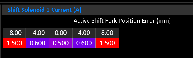
Manipulating the current through the shift solenoid allows the fork movement to be slowed as it approaches the target.
Selector Forks
| Fork | Gear Low | Gear High |
|---|---|---|
| 1 | 4 | 6 |
| 2 | 2 | R |
| 3 | 1 | 3 |
| 4 | 5 | 7 |
Reverse and 2nd are on different clutches.
Fork 2 must be assigned to Axis A & B to inform the system that this is not a config mistake.
Gear to Fork Mapping
The following table shows the nominal fork mapping. Actual positions should be fine tuned with real world measurements see during operation.
| Gear | Fork | Position | Volts |
|---|---|---|---|
| R | 2-H | 8.0mm | 3.830 |
| N | ALL | 0.0mm | 2.500 |
| 1 | 3-L | -8.0mm | 1.360 |
| 2 | 2-H | -8.0mm | 1.360 |
| 3 | 3-H | 8.0mm | 3.830 |
| 4 | 1-L | 8.0mm | 3.830 |
| 5 | 3-H | 8.0mm | 1.360 |
| 6 | 1-H | -8.0mm | 1.360 |
Shift Solenoids
| Solenoid | Function |
|---|---|
| 1 | Fork Move +/- |
| 2 | Fork Move +/- |
| 3 | Fork Select B0 |
| 4 | Fork Select B1 |
Shift Solenoid Truth Table
| Fork | Gear | Sol 1 | Sol 2 | Sol 3 | Sol 4 |
|---|---|---|---|---|---|
| 1 (4/6) | 4 « | X | X | ||
| 1 (4/6) | » 6 | X | X | ||
| 2 (2/R) | R « | X | |||
| 2 (2/R) | » 2 | X | |||
| 3 (1/3) | 1 « | X | X | ||
| 3 (1/3) | » 3 | X | X | ||
| 4 (5/7) | 5 « | X | X | X | |
| 4 (5/7) | » 7 | X | X | X |
Line Pressure
The line pressure solenoid reduces line pressure as current increases. Maximum line pressure is achieved when the solenoid is completely off.
No line pressure sensor is available.
Clutch Pressure
Clutch pressure is controlled by a solenoid for each clutch. To achieve maximum pressure they must be driven to approximately 1.8-1.9 Amps. To do so, the solenoids need to be wired to a Solenoid Pair so that more than 1.5A can be targeted.
- Each clutch has a pressure sensor.
- Each clutch/axis has a safety solenoid that must be energized to allow clutch pressure to be applied.
Input Shaft Speed
An Input Shaft Speed sensor is available. This effectively measures engine RPM as it’s the speed BEFORE the input to the clutch baskets.
The sensor is 2 wire hall effect type. Use Hall Input 1-4.
Clutch Speeds
Each Clutch has an output speed sensor. The sensor measures the speed of the output side of the clutch basket. This speed varies depending on the selected gear.
Slip is calculated based on the difference between Input Shaft Speed and Clutch A/B Speed.
The sensors are 2 wire hall effect type. Use Hall Input 1-4.
Output Shaft Speed
The GS7 does not have an output shaft speed sensor. Instead, leave the Output Shaft Speed input OFF and the TCM will calculate Output Shaft Speed using the active clutch and it’s currently selected gear.
Lubrication / Cooling Flow
The GS7 has a solenoid dedicated to cooling the clutches.
Nissan GR6
Wiring
Refer to the Emtron TM16-R35 Adapter Kit Datasheet.
Gear Ratios
| Gear | Ratio |
|---|---|
| R | -3.383 |
| 1st | 4.056 |
| 2nd | 2.301 |
| 3rd | 1.595 |
| 4th | 1.248 |
| 5th | 1.001 |
| 6th | 0.796 |
| FD | 3.700 |
Shift Forks
| Fork | Gear Low | Gear High |
|---|---|---|
| 1 | R | 1 |
| 2 | 2 | 4 |
| 3 | 3 | 5 |
| 4 | 6 | - |
Gear to Fork Mapping
| Gear | Fork | Position | Volts |
|---|---|---|---|
| R | 1-L | -9.0mm | 1.300 / 3.800* |
| N | ALL | 0.0mm | 2.500 |
| 1 | 1-H | 9.0mm | 3.800 / 1.300* |
| 2 | 2-L | 9.0mm | 1.300 |
| 3 | 3-L | 9.0mm | 1.300 |
| 4 | 2-H | -9.0mm | 3.800 |
| 5 | 3-H | -9.0mm | 3.800 |
| 6 | 4-L | 9.0mm | 1.300 |
* Fork 1 has two position sensors.
Shift Solenoids
| Solenoid | Function |
|---|---|
| 1 | 4 / N |
| 2 | 2 / 6 |
| 3 | R / 5 |
| 4 | 1 / 3 |
| 5 | Fork 3 & 4 Select |
Shift Solenoid Truth Table
| Fork | Gear | Sol 1 | Sol 2 | Sol 3 | Sol 4 | Sol 5 |
|---|---|---|---|---|---|---|
| 1 (1/R) | R « | X | ||||
| 1 (1/R) | » 1 | X | ||||
| 2 (2/4) | 2 « | X | ||||
| 2 (2/4) | » 4 | X | ||||
| 3 (3/5) | 3 « | X | X | |||
| 3 (3/5) | » 5 | X | X | |||
| 4 (6/N) | 6 « | X | X | |||
| 4 (6/N) | » N | X | X |
Axis Feed Pressure Solenoids
Active Axis/Clutch Behavior
Maintains about 3.5 bar above the active clutch pressure target.
Inactive Axis/Clutch Behavior
Holds 10 bar at most times. During fork movement, the inactive axis pressure is used to control the shift fork movement force and velocity. Once the fork is in position it returns to 10 bar.
Lubricating Flow Solenoid
Remains active by default, allowing fully lubrication and cooling flow. During a shift or high torque demand it will close off, to reduce pressure drop and allow maximum line pressure availability.
Known Issues / Limitations
Start Button Hold to Start
The R35 TCM is responsible for determining that the engine is safe to crank and supplies the positive side of the starter relay with power when the transmission is in Park or Neutral. The window of time for this to happen when the start button is held from fully off, with brake applied, is only a couple of hundred milliseconds. The TM16’s boot up process takes slightly longer than the factory TCM because it runs a very complex CPU & FPGA. As a result, the starter relay receives power too late. The starter solenoid will click but the BCM will have already given up. The R35 base cal has a deliberate delay added to the user function that drives the starter relay power so that the one shot hold to start does not work at all. Instead the ignition will turn on normally, and the engine will start with a second press of the start button.
Hill Hold
The OEM hill hold function that tells the ABS module to lock the brakes on a hill is not currently supported. We intend to add support for this function in a future update.
Limp Home Skip Shifting
When an axis/clutch detects an error the OEM TCM will lockout the problem axis and skip shift (eg 2 to 4 to 6, ignoring 1,3,5 or visa versa). Current firmware does not support this function. Full fault detection is implemented and every shift fork is monitored for correct positioning at all times including before a shift can occur. In the event of a fault (such as a fork being stuck in the wrong position), rather than skip shift, the transmission will remain in whatever gear is currently driving. Full limp home skip shifting is planned for a future update.
ZF 8HP
Models
Caution
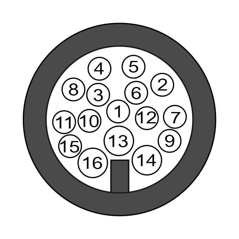
Currently, only 8HP models with 16 pin connectors are compatible. Models with only 10 pins do not have the required IO to allow an external TCM.
| Model | Support | Comment |
|---|---|---|
| 8HP45 | Y | Gen 1 |
| 8HP50 | Y | Gen 2 |
| 8HP51 | N* | Gen 3 *Requires Gen 2 valve body |
| 8HP70 | Y | Gen 1 |
| 8HP75 | Y | Gen 2 |
| 8HP76 | N* | Gen 3 *Requires Gen 2 valve body |
| 8HP90 | Y | Gen 1 |
| 8HP95 | Y | Gen 2 |
Base Calibration
A base calibration based on the 8HP70 is included with TMtune. Solenoid pressure translation tables are also included separately.
Wiring
Mechatronics Modifications
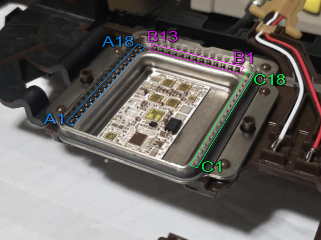
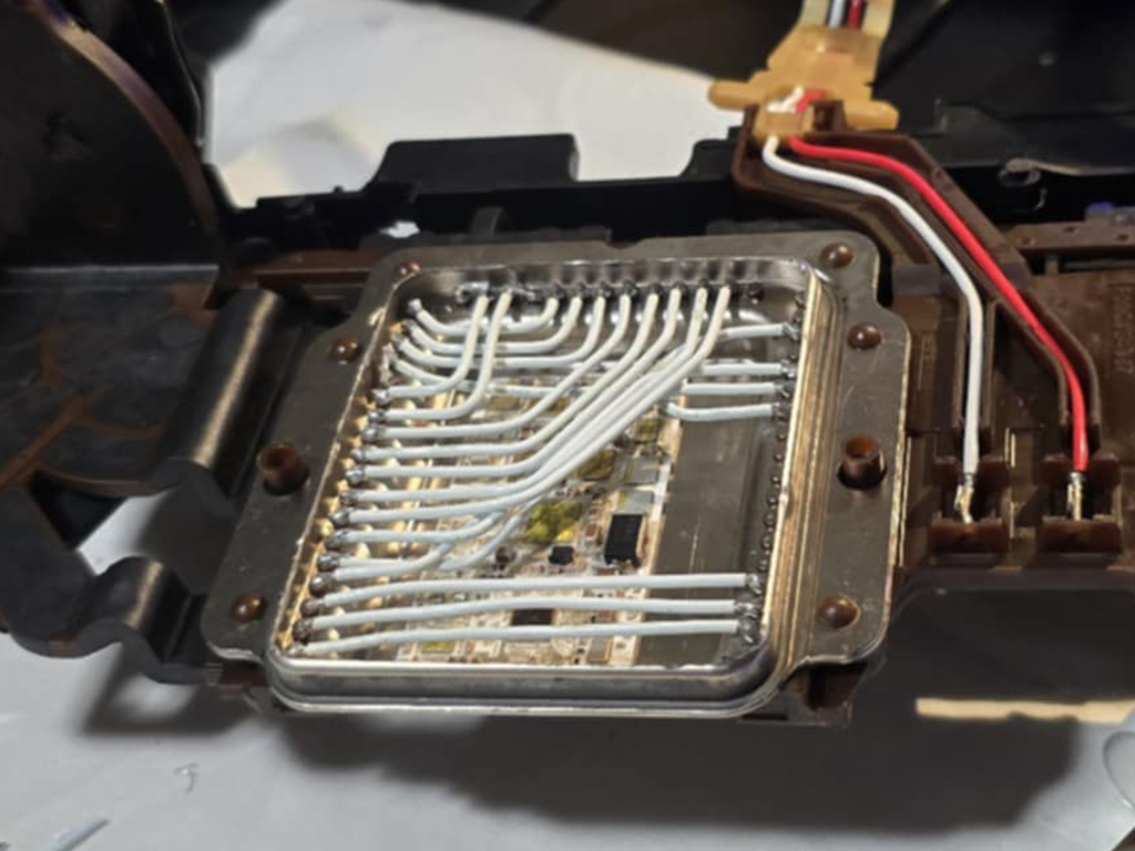
In order to control the 8HP transmission, the internal mechatronics unit must be bypassed and the control signals routed externally.
- Remove the mechatronics assembly from the transmission.
- Cut the lid off the OEM TCM enclosure.
- Cut all the fine wire connections between the OEM TCM and the interface pads.
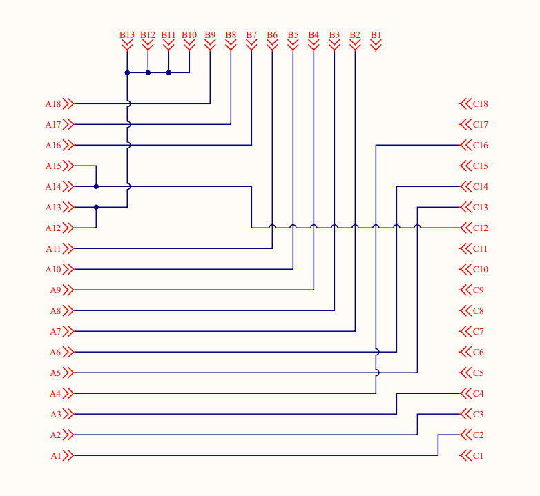
- Wire connections between pads as follows…
Caution
22 AWG or 24 AWG Tefzel wire should be used to bridge connections as it can withstand the temperatures and oil present inside the transmission.
For simplicity and compatibility we’re using the same pin designations as the DomiWorks 8HP Wiring Kit.
| IO Pin (A) | Internal Pin (B/C) |
|---|---|
| A1 | C2 |
| A2 | C3 |
| A3 | C4 |
| A4 | C16 |
| A5 | C13 |
| A6 | C14 |
| A7 | B2 |
| A8 | B3 |
| A9 | B4 |
| A10 | B5 |
| A11 | B6 |
| A12 | B10, B11, B12, B13 |
| A13 | B10, B11, B12, B13 |
| A14 | C12 |
| A15 | C12 |
| A16 | B7 |
| A17 | B8 |
| A18 | B9 |
Potting
We have found that potting the modified mechatronics units with compounds such as R125 has resulted in repeated failures. There appears to be a negative interaction between R125 and the oil used in the 8HP transmissions. The most reliable results we have seen have come from NOT potting the internal connections.
Gearbox Connector
Important
Pinout assumes mechatronic modifications have been completed as detailed above.
| Pin | Function | TCM Pin *1 |
|---|---|---|
| 1 | Sensor 0V Ref | Sensor GND (A9) |
| 2 | Line Pressure Solenoid | Sol 6 (B15) |
| 3 | Speed Sensor 8V Supply | 8V Out (C18) |
| 4 | Accumulator Solenoid | Sol 10 (B19) |
| 5 | Park Hold Solenoid | Sol 9 (B18) |
| 6 | Park Release Solenoid | Sol 8 (B17) |
| 7 | Clutch C Solenoid | Sol 3 (B12) |
| 8 | Input Shaft Speed Signal | DI 1 (A18) |
| 9 | Clutch E Solenoid | Sol 5 (B14) |
| 10 | Output Shaft Speed Signal | DI 2 (A19) |
| 11 | Brake A Solenoid | Sol 1 (B10) |
| 12 | TC Lockup Solenoid | Sol 7 (B16) |
| 13 | Trans Fluid Temp Sensor | An 1 (A1) |
| 14 | Solenoid Power Supply | Sol +V Out (B30+B31) *2 |
| 15 (Gen 1) | Clutch D Solenoid | Sol 4 (B13) *3 |
| 15 (Gen 2) | Brake B Solenoid | Sol 4 (B13) *3 |
| 16 (Gen 1) | Brake B Solenoid | Sol 2 (B11) *3 |
| 17 (Gen 2) | Clutch D Solenoid | Sol 2 (B11) *3 |
1. This pinout matches the supplied 8HP base calibration. You’re free to alter the TCM pin assignments as long as the change is reflected in the config.
2. Ideally each 4 solenoids would have a separate supply bank, but this isn’t possible using the OEM connector. Connecting to two bridged solenoid supplies will suffice.
3. To cater for Gen 1 vs Gen 2, swap the Brake B / Clutch D solenoid assignment in config OR swap pins 15 / 16 in the wiring harness.
Speed Sensors
- Input Shaft Speed
- Output Shaft Speed
The sensors are 2-wire hall effect type, however the polarity of the internal wiring means the dedicated hall sensor inputs on the TCM cannot be used. Instead, the sensors can be wired to Digital Inputs 1 to 8. The internal 330R pulldown must to be enabled.
In this arrangement, the signal voltage will sit at around 2V when stationary, and pulse up to around 4V when a tooth passes the sensor.
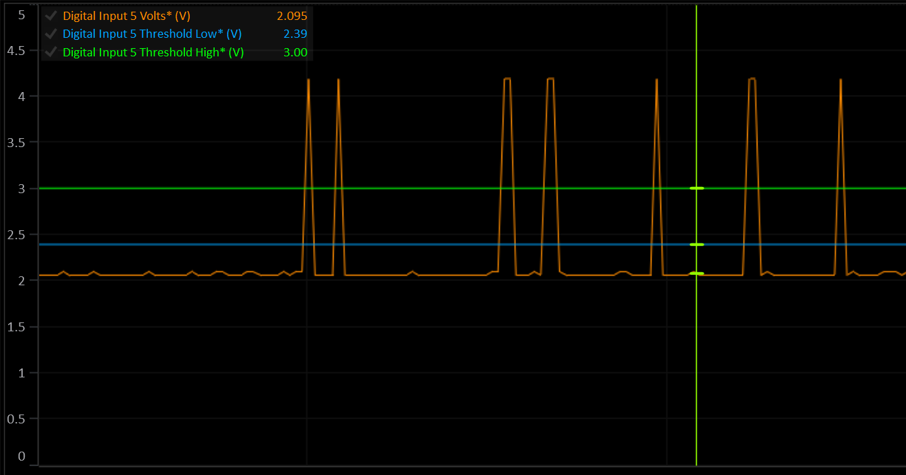
The high and low arming thresholds must be set correctly to detect the speed signal. The low threshold must be ABOVE the sensor voltage at rest, and the high threshold must be BELOW the maximum voltage when the sensor is active.
Speed Sensor Calibration
| Model | Input Shaft Speed | Output Shaft Speed |
|---|---|---|
| 8HP50 | 28 Teeth | 40 Teeth |
| 8HP70 | 30 Teeth | 40 Teeth |
Solenoids
The ZF 8HP contains nine solenoids. All but the park-release/hold solenoids are Variable‐Force Solenoids (VSF). The park‐release and park‐hold are on/off.
Shift Elements
The 8HP uses the following “shift elements”:
- Two fixed multidisc brakes (brake A and B)
- Three rotary multidisc clutches (clutch C, D and E).
The multidisc clutches (C, D and E) feed the drive torque to the planetary gear. The multidisc brakes (A and B) support the torque against the transmission housing.
| Solenoid | Shift Element | Note |
|---|---|---|
| Clutch Solenoid A | Brake A | VFS, normally vented (no pressure when off). |
| Clutch Solenoid B | Brake B | VFS, normally vented (no pressure when off). |
| Clutch Solenoid C | Clutch C | VFS, normally applied (high pressure when off). |
| Clutch Solenoid D | Clutch D | VFS, normally applied (high pressure when off). |
| Clutch Solenoid E | Clutch E | VFS, normally applied (high pressure when off). |
Line Pressure Solenoid
VFS, normally applied. Modulates the valve-body pressure regulator to maintain the transmission’s main hydraulic (line) pressure under all operating conditions.
Torque Converter Clutch (TCC) Solenoid
VFS, normally vented. Controls apply pressure to the lock-up piston in the torque converter for smooth lock/unlock transitions.
Park Release Solenoid
On/Off, normally open. When energized, it directs line pressure to the park-release valve to retract the parking pawl, allowing selection of Drive or Reverse.
Park Hold Solenoid
Mechanical. Clips onto and holds the park-release piston in its disengaged position after the pawl is withdrawn. Does not flow hydraulic oil.
Clutch Geometry
The following data is provided as a guide based on the best information available at time of writing.
8HP70
| Clutch | Plates (S/D) | Friction ID/OD (mm) | Piston ID/OD (mm) |
|---|---|---|---|
| Brake A | 5 (D) | 126.0 / 144.0 | 99.5 / 144.1 |
| Brake B | 5 (D) | 176.0 / 196.0 | 168.9 / 206.5 |
| Clutch C | 6 (D) | 139.0 / 163.0 | 44.8 / 95.7 |
| Clutch D | 4 (D) | 149.0 / 172.0 | 47.5 / 126.7 |
| Clutch E | 5 (D) | 139.0 / 163.0 | 46.0 / 116.0 |
Gear Sequencing
By engaging different combinations of the five shift elements listed above, the transmission obtains each of its eight forward ratios (plus reverse).
| Gear | Brake A | Brake B | Clutch C | Clutch D | Clutch E |
|---|---|---|---|---|---|
| P | |||||
| R | X | X | X | ||
| N | |||||
| 1 | X | X | X | ||
| 2 | X | X | X | ||
| 3 | X | X | X | ||
| 4 | X | X | X | ||
| 5 | X | X | X | ||
| 6 | X | X | X | ||
| 7 | X | X | X | ||
| 8 | X | X | X |
Clutch Gear Load Factor
The ratio of input torque that each clutch/brake element carries for a given gear.
| Gear | Brake A | Brake B | Clutch C | Clutch D | Clutch E |
|---|---|---|---|---|---|
| R | 0.333 | 2.594 | - | 3.296 | - |
| N | - | - | — | - | - |
| 1 | 0.333 | 3.695 | 1.000 | - | - |
| 2 | 0.333 | 2.463 | - | - | 0.667 |
| 3 | - | 1.103 | 1.000 | - | 1.000 |
| 4 | - | 1.111 | - | 1.666 | 1.000 |
| 5 | - | 0.673 | 1.000 | 1.284 | - |
| 6 | - | - | 1.000 | 1.000 | 1.000 |
| 7 | 0.220 | - | 1.000 | 1.739 | - |
| 8 | 0.222 | - | - | 0.666 | 0.666 |
Pressure Control
The 8HP does not have any pressure sensors. This means that all internal pressures are inferred from solenoid current. Because the TCM uses pressure targets it’s important to get the solenoid pressure translations as accurate as possible. The supplied 8HP base calibration includes pressure translation tables taken from OEM roms. In most cases these do not need to be changed.
Optionally, you may enable Line Pressure and/or Clutch Pressure estimations to give feedback based on actual solenoid activity and fluid temperature.