Clutch Modelling
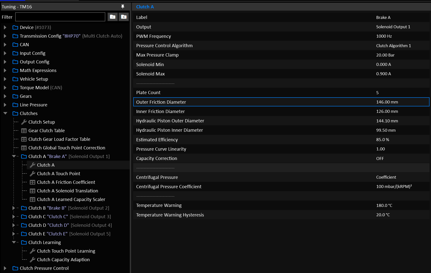
The TCM will use the clutch geometry model to calculate the torque capacity of each clutch. These settings are critical to correct transmission behavior.
Clutch Geometry
Clutch geometry is taken into account in two directions:
- Calculating how much pressure to apply to hold a given torque.
- Calculating how much torque a given pressure can hold.
Plate Count
The number of friction plates in the clutch assembly. Aftermarket clutch kits often have increased plate counts, make sure to enter the correct number here.
Friction Diameters
The inner and outer diameters of the friction plate(s) should be entered accurately. Ideally these should be physically measured.
Hydraulic Piston Diameters
The hydraulic piston refers to the chamber that is filled with fluid in order to apply clamping force to the clutch. In the case of a fully open chamber without a shaft running through it (cylinder as opposed to a doughnut), an inner diameter of 0.0mm is valid.
Estimated Efficiency
Estimates the inefficiencies or mechanical losses involved in converting a given hydraulic pressure to a clamping torque capacity.
Typical Value: 85.0%
Pressure Curve Linearity
Bends the clutch’s Torque to Pressure translation into a non linear curve.
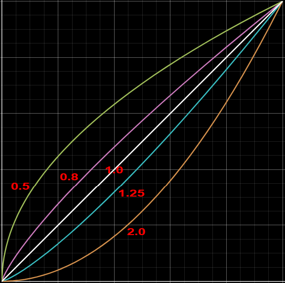
Typical Value: 1.00
Capacity Correction
Enables a table that allows the user to manipulate the final calculations.
In most cases this should NOT be used.
Typical Value: OFF
Clutch Friction Coefficient
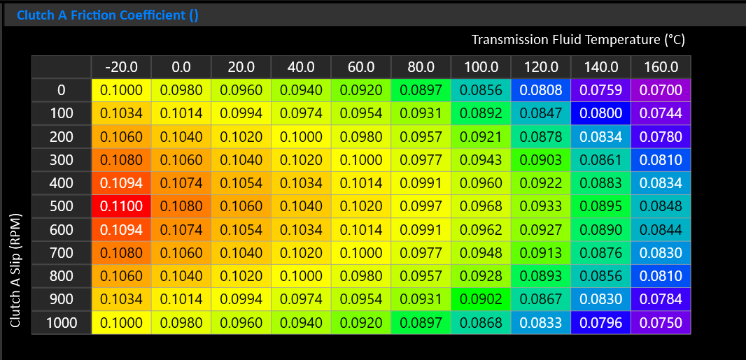
This table controls the frictional behavior of the clutch. Typically a wet clutch will have an increase in friction as it heats up with moderate slip, before falling back off as slip increases.
If you’re unsure, a generic table is provided that can be loaded in as a good starting point.
Centrifugal Pressure
Wet clutch drums spinning at speed generate centrifugal hydraulic pressure that acts on the piston independently of commanded pressure. At high drum speeds this can cause an offgoing clutch to partially engage even when you command only touch-point pressure.
On some transmissions dragging will be evident as a torque interruption or slip resistance during rev-matched downshifts. It may feel like the car is being pushed when the clutches should be fully slipping.
Select the mode used to calculate Clutch Centrifugal Pressure.
- Modelled = Clutch geometry based.
- Coefficient = Uses a coefficient that is independent of clutch geometry.
Modelled Centrifugal Pressure
When Clutch Centrifugal Pressure is in Modelled mode, the Clutch’s Centrifugal Pressure is calculated using the clutch geometry. Cancellation Efficiency represents how well the clutch resists the build up of centrifugal pressure.
- 0% = Full Modelled Centrifugal Pressure, maximum correction.
- 100% = No Modelled Centrifugal Pressure, no correction.
Centrifugal Pressure Coefficient
The coefficient compensates by subtracting from the total target pressure for the offgoing clutch.
- Start at 0 (disabled).
- Increase in steps of 20-30.
At 3000 RPM, each step of 10 removes appox. 0.09 bar of commanded pressure.
Typical Value: 0 or 100 - 200
Clutch Gear Load Factor
Not required for DCT Transmissions
Tip
This table is considered “Set & Forget”. It should be setup early on and left, rather than used as a tuning table.
Multi-clutch automatic transmissions use multiple clutches and brakes to create each gear. These elements do not share torque equally. Depending on the gear ratio and planetary gearset layout, one element may carry much more reaction torque than another. Each clutch will often have a different input torque applied to it depending on the combinations of clutches and gears also applied for a particular gear.
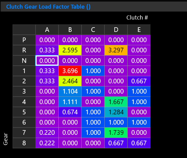
The Clutch Gear Load Factor table accounts for this internal torque multiplication on a per gear and per clutch basis.
This allows the TCM to estimate how much torque capacity each applied element needs in each gear.
Important
- X Axis must be “Clutch #”
- Y Axis must be “Gear”
- Z Axis is not used
The values in this table are not gear ratios or pressure multipliers. They are torque-capacity multipliers used before the torque-to-pressure calculation.
The resultant input torque for each clutch is shown by the “Clutch N Input Torque” runtime.
Important Notes:
- Load Factors can be calculated from the transmissions gear set.
- Only elements that are applied in a gear should have non-zero values. Elements that are released in that gear should be set to zero.
- Increasing a value will increase the calculated torque capacity requirement for that element in that gear, resulting in higher commanded pressure.
- Decreasing a value will reduce the calculated pressure requirement.
- If the value is too low, the clutch or brake may slip under load.
- If the value is too high, the shift or gear engagement may become harsh, inefficient, or create unnecessary clutch stress.
- It’s recommended to set each Clutch’s Learned Capacity Scaler Table Y axis of “Gear”. This allows the clutches to learn on a per-gear basis.