Clutch Pressure Control
The TCM needs to apply pressure to the clutch(s) in two main scenarios:
- In Gear (Active Clutch Pressure)
- During a shift
Other sub systems such as Takeup can takeover the clutch pressure control. They’re documented separately.
Active Clutch Pressure
The Active Clutch Pressure refers to the pressure applied to a clutch that is transmitting normal in-gear torque. The primary influencing factor on Active Clutch Pressure is Torque.
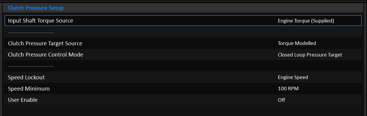
Input Shaft Torque Source
Torque based clutch pressure uses the Input Shaft Torque runtime for it’s calculations. The source of Input Shaft Torque can come from:
- Engine Torque (Supplied)
- Engine Torque (Available)
- Engine Torque (Supplied & Inertia Corrected)
Most setups would use
Engine Torque (Supplied).
Clutch Pressure Target Source
The pressure applied can be calculated in a number of ways:
- Torque Modelled
- User Defined
- Line Pressure Controlled
Tip
DCT Transmissions should almost always use Torque Modelled mode.
Target Source: Torque Modelled
---
title: Torque Modelled Clutch Pressure
---
graph LR;
  Prs(Clutch Pressure) -->|Bar| PID(PID)
  Tq(Input Shaft Torque) -->|Nm| TqCap{Sum: Required Torque Capacity}
  Clamp(Clamping Torque Margin) -->|Nm| TqCap
  TqCap -->|Nm| Geo(Clutch Model)
  Geo -->|Bar| Src{<strong>Clutch Pressure Target Source</strong>}
  Src -->|Bar| Sol(Solenoid Translation)
  Sol -->|Amps| PID
  PID --> |Amps| Curr[Solenoid Current]
  Src -->|Bar| PID
It is absolutely critical that the engine torque data is accurate.
Clutch Pressure is calculated using the Clutch’s geometry model. The pressure that comes out of the clutch model is intended to be the minimum pressure required to hold a given input torque, no more. The user can (and should) apply a Clamping Torque Margin on top of the Input Shaft Torque so that the clutch is commanded to hold slightly more torque and apply a slightly higher pressure as a result.
PID Control can be enabled if a Clutch Pressure Sensor is available.
For detailed information on how to setup the clutch model, see the Clutch Model documentation.
Target Source: User Defined
---
title: User Defined Clutch Pressure
---
graph LR;
  Prs(Clutch Pressure) -->|Bar| PID(PID)
  Tgt(Active Clutch Pressure Target) -->|Bar| TgtFnl{Target * Correction \+ Offset}
  Corr(Active Clutch Pressure Correction) -->|%| TgtFnl
  Offs(Active Clutch Pressure Offset) -->|Bar| TgtFnl
  TgtFnl -->|Bar| Src{<strong>Clutch Pressure Target Source</strong>}
  Src -->|Bar| Sol(Solenoid Translation)
  Sol -->|Amps| PID
  PID --> |Amps| Curr[Solenoid Current]
  Src -->|Bar| PID
In user defined mode, the Clutch Pressure Target simply comes from a Table. Optionally a Correction and Offset can be applied.
PID Control can be enabled if a Clutch Pressure Sensor is available.
Target Source: Line Pressure Controlled
---
title: Line Pressure Controlled Clutch Pressure
---
graph LR;
  LnPrs(Line Pressure) -->|Bar| Src{<strong>Clutch Pressure Target Source</strong>}

  PrsMax(Clutch Model: Max Pressure) --> |Bar| Sol(Solenoid Translation)
  Sol --> |Amps| Curr[Solenoid Current]
This mode is a special case for transmissions that simply expose all active clutches to full line pressure when in gear. This is the case for transmissions such as the ZF 8HP.
The Pressure Target and Solenoid Current are completely decoupled in this mode:
- The clutch solenoid is held at the current that achieves the maximum pressure (as configured in the Clutch Setup) according to it’s Solenoid Translation table.
- Line Pressure is copied into the
Active Clutch Pressureand Clutch # Pressure Target runtimes simply to give them something useful to display.
PID control cannot be used.
Shift Pressures
During a shift, the clutch pressure is fully modelled. No user defined pressure mode is available. The process of controlling a shift with user defined tables would put an enormous tuning burden on the end user that would require a lot of time to configure. The user can still tune a lot about how the shift feels, they just don’t have to worry about the actual pressures involved.
Calculating the pressure during a shift is very similar to when in gear, but the input torque will depend on weather the clutch is oncoming or offgoing, and the phase of the shift.
---
title: Torque Modelled Clutch Pressure
---
graph LR;
  Prs(Clutch Pressure) -->|Bar| PrsPid(Pressure PID)
  Tq(Input Shaft Torque) -->|Nm| ShtTq{Clutch/Phase/Slip Torque Manipulation}
  EngIn(Engine Inertia) -->|kg⋅m²| ShtTq
  EngSpdDt(Engine Speed Delta) -->|RPM/s| ShtTq
  GearSpd(Oncoming/Offgoing Gear Speeds) -->|RPM| ShtTq
  SlpTgt(Slip Target) -->|RPM| ShtTq
  Slip(Clutch Slip) -->|RPM| ShtTq
  ShTime(Shift Time Targets) -->|ms| ShtTq

  SlpTgt(Slip Target) -->|RPM| ShtPid
  Slip(Clutch Slip) -->|RPM| ShtPid
  ShtTq -->|Nm| ShtPid(Shift PID)
  ShtPid -->|Nm| TqFinal(Shift Torque)
  TqFinal -->|Nm| Geo(Clutch Model)
  PrsRate(Clutch Pressure Rate Limits) -->|Bar/s| Src
  Geo -->|Bar| Src{<strong>Clutch Pressure Target</strong>}
  Src -->|Bar| Sol(Solenoid Translation)
  Sol -->|Amps| PrsPid
  PrsPid --> |Amps| Curr[Solenoid Current]
  Src -->|Bar| PrsPid
It is absolutely critical that the engine torque data is accurate.
For detailed information on the shift phases, see the Multi-Clutch Shifting documentation.
For detailed information on how to setup the clutch model, see the Clutch Model documentation.