Emtron ECU Integration
This document details the steps required for the TCM and ECU to integrate with each other.
Minimum ECU Firmware Version: 2.21.0
TM16 to Emtron ECU CAN Protocol
The TM16 CAN protocol uses ID’s in the range of 336 to 345 (0x150 to 0x159). Care must be taken to ensure that no other devices are using ID’s withing that range.
Channels controlled by Input Functions (eg: Engine Speed) must have their input source set to CAN.
Transmission Channels
The following channels are transmitted by the TCM:
- Gear
- Gear Request (Next Gear)
- Input Shaft Speed
- Output Shaft Speed
- Torque Limit (Slow / Throttle)
- Torque Limit (Fast / Ignition)
- Up Shift Switch
- Down Shift Switch
- Transmission Fluid Temp
Engine Channels
The following channels are transmitted but the ECU:
- Engine Speed
- Manifold Absolute Pressure
- Throttle Area Demand
- Pedal Position Demand
- Engine Torque (No Reductions)
- Engine Torque (Final)
- Driver Demand Torque
- Brake Switch
- Engine Temperature
- Idle Target
- Idle Status
- Overrun Fuel Cut Status
- CE Light
TM16 Setup
- Set up the CAN Bus:
- Ensure the CAN Node is set to the same bitrate as the ECU (eg: 1 MBps)
- Ensure the CAN bus is correctly terminated
- Ensure proper CAN bus topology and wiring
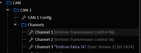
- Assign a CAN Channel to: “Emtron Transmission Control Rx”
- Assign a second CAN Channel to: “Emtron Transmission Control Tx”
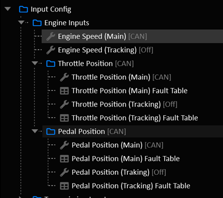
- Set the following input function sources to “CAN”:
- Engine Speed (Main)
- Throttle Position (Main)
- Pedal Position (Main)
- Manifold Absolute Pressure
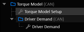
- Set the Torque Model to CAN:
- Torque Model Source
- Driver Demand Source
ECU Setup
- Set up the CAN Bus:
- Ensure the CAN Node is set to the same bitrate as the TCM (eg: 1 MBps)
- Assign a CAN Channel to “Emtron TM16”.

- Enable Gearshift Control: Emtron TM16
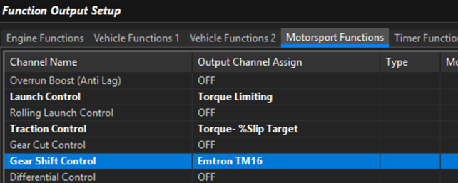
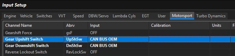
- Assign the following inputs to “CAN Bus OEM”:
- Input Shaft Speed
- Output Shaft Speed
- Gear Upshift Switch
- Gear Downshift Switch
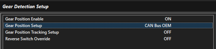
- Assign Gear Detection to “CAN Bus OEM”
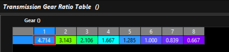
Fill in the Transmission Gear Ratio Table to match the TCM
Setup the Torque Model
- Normal Torque Model validation applies. Ensure the torque model is well sorted and frictional loss is validated.
- Set the CAN Bus Reported Torque Modifier Tables to zero unless you have a specific reason to change it.
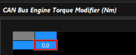
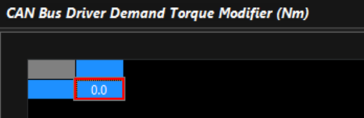
It is critical that the ECU’s torque model is well sorted.
- In the TM16 Menu:
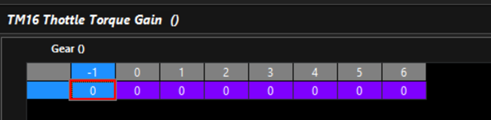
- Set TM16 Throttle Torque Gain to Zero
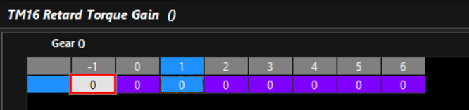
- Set TM16 Retard Torque Gain to Zero
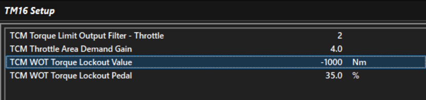
- Set TCM WOT Torque Lockout Value to -1000 to disable
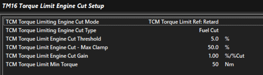
- Setup the Engine Cut Setup to suit your application
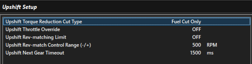
- Up Shift Setup:
- In Motorsport > Geashift Control TM16: Configure the upshift to your application.
- Down Shift Setup:
- In Motorsport > Gearshift Control TM16, configure Downshift for your application.
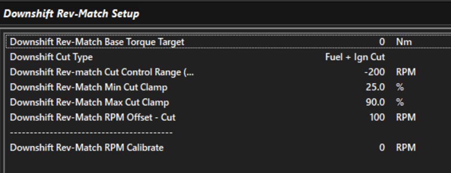
Most applications will use a Base Torque Target of 0 nm. This results in the engine holding itself at the rev match target until the clutch grabs it.
- Set up the Downshift Rev-Match Torque Target Margin Table:
This is the amount of torque applied at the start of the downshift to get the engine to the Rev-Match target. Engine torque is reduced to the Base Torque Target as the engine speed reaches the Rev-Match Target.

Important Notes
Upshift Switch
Upshift Switch is only transmitted when the TCM wants a torque limit during the shift. Otherwise, the Gear Request value will simply change to the next gear and the shift will progress without torque intervention. The ECU will abide by the torque limit specified by the TCM during a shit.
Downshift Switch
Downshift Switch is only transmitted when the TCM wants a Rev-Match. Otherwise, the shift will happen without intervention.
Rev Match Target
The ECU will calculate its own Rev-Match target RPM based on the Output Shaft Speed and Gear Ratio.
It is critical that the gear ratio table is correct.