Subsections of Tuning
Emtron ECU Integration
This document details the steps required for the TCM and ECU to integrate with each other.
Minimum ECU Firmware Version: 2.21.0
TM16 to Emtron ECU CAN Protocol
The TM16 CAN protocol uses ID’s in the range of 336 to 345 (0x150 to 0x159). Care must be taken to ensure that no other devices are using ID’s withing that range.
Channels controlled by Input Functions (eg: Engine Speed) must have their input source set to CAN.
Transmission Channels
The following channels are transmitted by the TCM:
- Gear
- Gear Request (Next Gear)
- Input Shaft Speed
- Output Shaft Speed
- Torque Limit (Slow / Throttle)
- Torque Limit (Fast / Ignition)
- Up Shift Switch
- Down Shift Switch
- Transmission Fluid Temp
Engine Channels
The following channels are transmitted but the ECU:
- Engine Speed
- Manifold Absolute Pressure
- Throttle Area Demand
- Pedal Position Demand
- Engine Torque (No Reductions)
- Engine Torque (Final)
- Driver Demand Torque
- Brake Switch
- Engine Temperature
- Idle Target
- Idle Status
- Overrun Fuel Cut Status
- CE Light
TM16 Setup
- Set up the CAN Bus:
- Ensure the CAN Node is set to the same bitrate as the ECU (eg: 1 MBps)
- Ensure the CAN bus is correctly terminated
- Ensure proper CAN bus topology and wiring
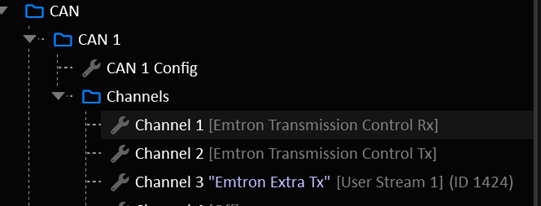
- Assign a CAN Channel to: “Emtron Transmission Control Rx”
- Assign a second CAN Channel to: “Emtron Transmission Control Tx”
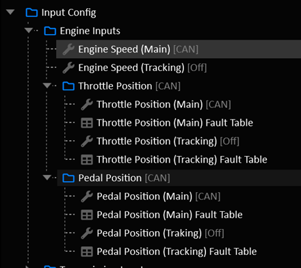
- Set the following input function sources to “CAN”:
- Engine Speed (Main)
- Throttle Position (Main)
- Pedal Position (Main)
- Manifold Absolute Pressure
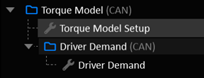
- Set the Torque Model to CAN:
- Torque Model Source
- Driver Demand Source
ECU Setup
- Set up the CAN Bus:
- Ensure the CAN Node is set to the same bitrate as the TCM (eg: 1 MBps)
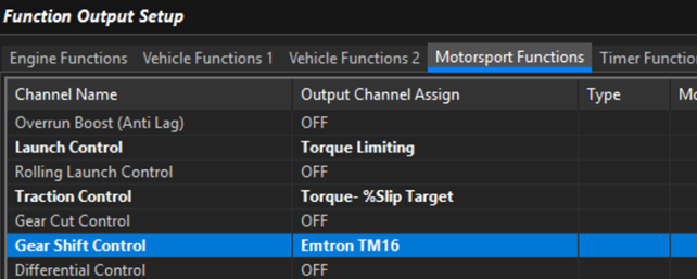
- Assign a CAN Channel to “Emtron TM16”.

- Enable Gearshift Control: Emtron TM16
- Assign the following inputs to “CAN Bus OEM”:
- Input Shaft Speed
- Output Shaft Speed
- Gear Upshift Switch
- Gear Downshift Switch
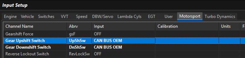
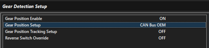
- Assign Gear Detection to “CAN Bus OEM”
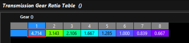
Fill in the Transmission Gear Ratio Table to match the TCM
Setup the Torque Model
- Normal Torque Model validation applies. Ensure the torque model is well sorted and frictional loss is validated.
- Set the CAN Bus Reported Torque Modifier Tables to zero unless you have a specific reason to change it.
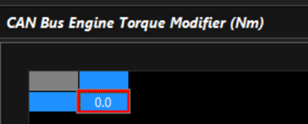
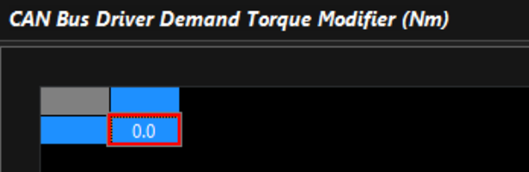
It is critical that the ECU’s torque model is well sorted.
- In the TM16 Menu:
- Set TM16 Throttle Torque Gain to Zero
- Set TM16 Retard Torque Gain to Zero
- Set TCM WOT Torque Lockout Value to -1000 to disable
- Setup the Engine Cut Setup to suit your application
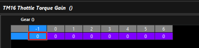
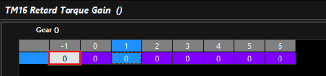
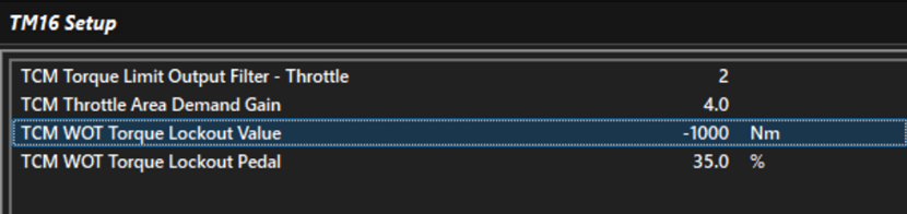
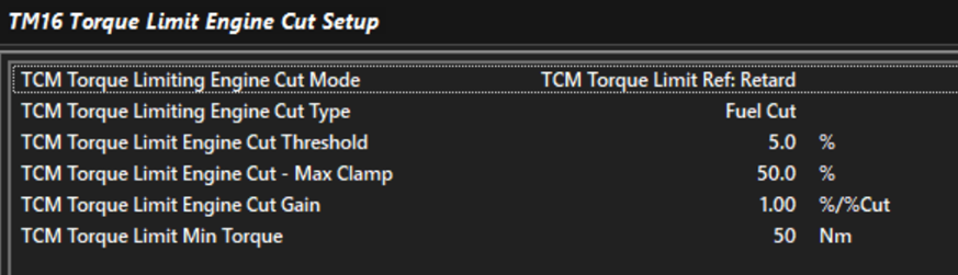
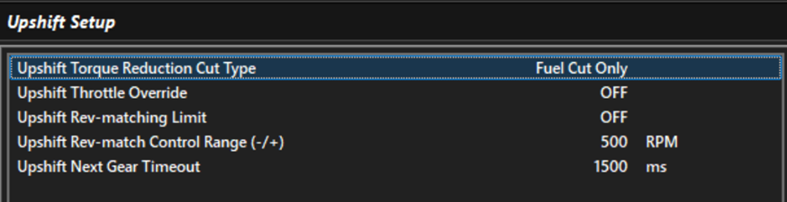
- Up Shift Setup:
- In Motorsport > Geashift Control TM16: Configure the upshift to your application.
- Down Shift Setup:
- In Motorsport > Gearshift Control TM16, configure Downshift for your application.
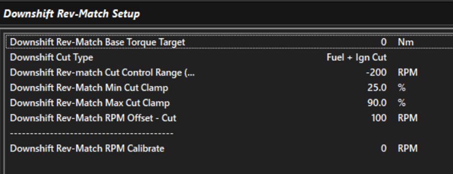
Most applications will use a Base Torque Target of 0 nm. This results in the engine holding itself at the rev match target until the clutch grabs it.
- Set up the Downshift Rev-Match Torque Target Margin Table:
This is the amount of torque applied at the start of the downshift to get the engine to the Rev-Match target. Engine torque is reduced to the Base Torque Target as the engine speed reaches the Rev-Match Target.

Important Notes
Upshift Switch
Upshift Switch is only transmitted when the TCM wants a torque limit during the shift. Otherwise, the Gear Request value will simply change to the next gear and the shift will progress without torque intervention. The ECU will abide by the torque limit specified by the TCM during a shit.
Downshift Switch
Downshift Switch is only transmitted when the TCM wants a Rev-Match. Otherwise, the shift will happen without intervention.
Rev Match Target
The ECU will calculate its own Rev-Match target RPM based on the Output Shaft Speed and Gear Ratio.
It is critical that the gear ratio table is correct.
Automatic Shifting
Automatic shifting chooses the gear in Drive and Sport. It can also add automatic up shifts, down shifts and kickdown to Manual mode, for example to shift up at the rev limit or down before the engine lugs.
There are three ways to tell the TCM when to shift:
- Speed - Simple: one up shift table and one down shift table give the speed to shift at.
- Speed - Per Gear: a separate table for every up shift and down shift.
- Gear Request: the table holds the gear to be in.
Whichever is used, every automatic shift still has to pass the same checks as a manual shift (input shaft speed limits, Takeup, time since the last shift and so on, see When an Automatic Shift Is Blocked).
Enabling
Turn on Enable in Automatic Shift > Auto Shift Setup. The rest of the settings and the Drive Mode, Sport Mode, Manual Mode and Hill Control folders appear once it is on.
| Setting | Description |
|---|---|
| Enable | Turns automatic shifting on. Also needed for the Manual mode automatic shifts. |
| Table Mode | Speed - Simple, Speed - Per Gear or Gear Request, see Table Modes. |
| Speed Reference | The channel the speed tables are compared against, see Speed Reference. Not used in Gear Request mode. |
| Gear Request Table Hysteresis | Gear Request mode only, see Hysteresis. |
| Sport Tables | Off: Sport uses the Drive Mode tables. On: Sport uses the tables in the Sport Mode folder. |
| Up / Down Shift Switch Behaviour | What an Up Shift or Down Shift switch press does in Drive or Sport, see Up / Down Shift Switches in Drive and Sport. |
| Manual Override Timeout | See Drive Modes. |
| Shift Lead Time Compensation | Starts shifts early to make up for the time a shift takes, see Shift Lead Time Compensation. In Drive and Sport it is used in the Speed modes. It is also used by the Manual mode automatic shifts in every Table Mode. |
| Hill Ascent Control, Hill Descent Control and their settings | See Hill Control. Speed modes only. |
Speed Reference
In the Speed modes, the up shift and down shift tables hold a speed, in the units of the Speed Reference:
| Speed Reference | Shift points are | Notes |
|---|---|---|
| Engine Speed | RPM | Includes torque converter slip, which can be large at low speed and high load. |
| Input Shaft Speed | RPM | Follows the gearbox directly. A good default. |
| Input Shaft Speed (Calculated) | RPM | Calculated from Output Shaft Speed and the current gear ratio. |
| Vehicle Speed, Drive Speed | km/h | A road speed. |
| Output Shaft Speed, Output Shaft Speed (Calculated) | RPM | Proportional to road speed. |
| Off | - | No automatic shifts in the Speed modes. |
With an RPM reference (engine or input shaft), the same number can suit every gear, for example “shift up at 6500 RPM at full pedal”. With a road-speed reference (vehicle, drive or output shaft speed), every gear needs its own shift points: use Speed - Per Gear, or put Gear on an axis of the Simple tables.
Skip shifts are worked out from the gear ratios, so they need an Engine Speed or Input Shaft Speed reference. With a road-speed reference each automatic shift moves one gear, see Skip Shifts.
Table Modes
| Table Mode | Shift tables (Drive Mode folder) | Shift tables (Sport Mode folder) |
|---|---|---|
| Speed - Simple | Drive Mode Up Shift Speed, Drive Mode Down Shift Speed | Sport Mode Up Shift Speed, Sport Mode Down Shift Speed |
| Speed - Per Gear | Drive Up Shift 1 to 2 … and Drive Down Shift 2 to 1 …, one for each shift up to the Number of Forward Gears | Sport Up Shift 1 to 2 …, Sport Down Shift 2 to 1 … |
| Gear Request | Drive Mode Gear Request | Sport Mode Gear Request |
Every mode also uses:
- Drive Mode Up Shift Enable and Drive Mode Down Shift Enable (and the Sport versions), see Shift Enable Tables.
- Drive Mode Shift Trigger Delay (and Sport Mode Shift Trigger Delay), see Shift Trigger Delay.
The table axes can be any channel. Typical choices are Pedal Position or Throttle Position against Gear, a speed, or Transmission Fluid Temperature.
Speed Modes
How a Shift Is Triggered
In Drive and Sport, every control cycle:
- Up shift when the Speed Reference is at or above the up shift speed, the Up Shift Enable table is on, and both have been true for longer than the Shift Trigger Delay.
- Down shift when the Speed Reference is at or below the down shift speed, the Down Shift Enable table is on, and both have been true for longer than the Shift Trigger Delay.
Up shifts are checked first. A shift speed of 0 means no shift in that direction.
In Speed - Simple mode with Gear on an axis, the column for a gear holds the shift point from that gear. In the up shift table, the gear 3 column is the 3 to 4 shift point. In the down shift table, it is the 3 to 2 shift point. Set the top gear’s up shift column to 0.
Up and Down Shift Speeds
Leave a gap between the up shift and down shift points, or the transmission will shift back and forth. With an RPM reference, check the speed after each shift:
- After an up shift the RPM drops by the ratio step. On a ZF 8HP, 6500 RPM in 2nd becomes about 4400 RPM in 3rd. The 3rd gear down shift speed must be well below that.
- After a down shift the RPM rises by the ratio step. The up shift speed for the lower gear must be well above that.
With a road-speed reference the speed doesn’t change through the shift, so simply keep each gear’s down shift speed below the speed it was up shifted at.
Typical shapes:
- Up shift speed rising with pedal: early, economical up shifts at light pedal, and full use of the engine’s speed range at full pedal.
- Down shift speed rising with pedal: pressing the pedal further down shifts sooner. This is the Drive mode kickdown.
Shift Enable Tables
The Up Shift Enable and Down Shift Enable tables switch automatic shifting in each direction on (1) or off (0), based on any channels. For example:
Transmission Fluid Temperature: hold lower gears while the fluid warms up.- Lateral acceleration: no up shifts mid-corner in Sport.
- A User Function or switch: a “hold gear” button.
Any value above 0 counts as on. Between an on cell and an off cell, the shift stays enabled right up to the off cell.
Shift Trigger Delay
The Shift Trigger Delay tables (ms) set how long a shift condition must hold before the shift is requested. This stops a speed that briefly crosses a shift point, or a quick pedal movement, from causing a shift. Putting Pedal Position on an axis lets kickdowns at high pedal be quick while light-pedal shifts wait longer.
The delay starts again after every shift, so each shift needs its own shift condition to hold for the delay.
The delay is also what allows skip shifts, see Skip Shifts.
Skip Shifts
Up Shift Stacking Limit and Down Shift Stacking Limit (Shift Setup > Up Shift > Up Shift Setup and Shift Setup > Down Shift > Down Shift Setup) set the most gears one automatic shift can move. 0 and 1 both mean one gear at a time for automatic shifts.
Above 1, the TCM keeps going to the next gear while the speed that gear would give is still past the shift point, for example dropping from 6th straight to 3rd when the pedal is floored. This needs an Engine Speed or Input Shaft Speed (or Input Shaft Speed (Calculated)) Speed Reference. A road speed doesn’t change when the gear changes, so with a Vehicle, Drive or Output Shaft Speed reference the stacking limits are not used and each automatic shift moves one gear. A skip shift never goes past the top gear or below the gear in the Initial Gear table. It is shortened to keep Input Shaft Speed between Input Shaft Speed Min and Input Shaft Speed Max. On a dual-clutch transmission a skip shift has to change to the other clutch, so the TCM may shorten it by a gear.
The number of gears is worked out when the Shift Trigger Delay runs out. A skip shift needs a Shift Trigger Delay above 0. With a delay of 0, the shift is requested the moment the shift point is crossed, when the speed is only just past it, so only one gear is ever justified and the transmission shifts one gear at a time whatever the stacking limit. The delay gives the speed, or a shift point that moves with the pedal, time to get further past, and that is what lets the TCM skip gears. For skip-shifting kickdowns, keep the delay short at high pedal, but not 0.
Tip
Start with both stacking limits at 1. Raise them only once the single-gear shift points are working, and check skip shifts in a log, including coming to a stop.
Gear Request Mode
In Gear Request mode, the Drive Mode Gear Request and Sport Mode Gear Request tables hold the gear to be in (1 to 12). The axes can be anything, typically Vehicle Speed against Pedal Position.
The table is interpolated, so between a 3 cell and a 4 cell its value moves smoothly from 3.0 to 4.0. The Auto Shift Gear Table channel shows the value.
Hysteresis
Gear Request Table Hysteresis (0-100%) sets how far past the halfway point between two gears the table value must go before the TCM shifts:
| Hysteresis | From 3rd, up shift to 4th at | From 4th, down shift to 3rd at |
|---|---|---|
| 0% | 3.50 | 3.50 |
| 50% | 3.75 | 3.25 |
| 100% | 4.00 | 3.00 |
At 100% the shift points are exactly where the cells are: up to 4th when the table reaches the 4 cell, back to 3rd only when it reaches the 3 cell. The spacing between neighbouring cells is then the hysteresis. 0% gives no hysteresis and isn’t recommended.
Holding the Gear
A cell of 0 means “hold the current gear”. Any table value below 1 holds.
Hold cells interpolate too
Between a 0 cell and a 4 cell, the table value passes through 1, 2 and 3, and those gears will be requested. Keep hold cells next to other hold cells, or put two axis breakpoints very close together where a hold region meets a gear region.
To hold the gear under particular conditions (a hold switch, cold fluid, cornering), the Up Shift Enable and Down Shift Enable tables are usually easier: they hold the gear without interpolating against the gear cells.
Limits
The table can ask for any gear, but each shift is limited:
- It moves no more than the stacking limit (see Skip Shifts). As in the Speed modes, a skip shift needs a Shift Trigger Delay above 0, so the table value has time to move more than one gear.
- It never goes above the top gear or below the gear in the Initial Gear table.
- An up shift is shortened to the highest gear that keeps
Input Shaft Speedabove Input Shaft Speed Min. A down shift is shortened to the lowest gear that keeps it below Input Shaft Speed Max. - The Up/Down Shift Enable and Shift Trigger Delay tables still apply.
Speed Reference, Shift Lead Time Compensation and Hill Control are not used by Gear Request mode. Shift Lead Time Compensation still applies to the Manual mode Auto Up Shift and Auto Down Shift.
Sport Mode
With Sport Tables on, Sport uses every table in the Sport Mode folder: the shift speed or gear request tables, the enable tables and the trigger delay. With it off, Sport behaves like Drive. See Drive Modes for how Sport is selected.
Shift Lead Time Compensation
A shift takes time to complete. While the speed is rising quickly, the engine is already past the up shift point by the time the shift finishes. With Shift Lead Time Compensation on, the TCM looks at how fast the Speed Reference is changing and starts the shift early by the amount it will change during the shift. Up shifts under hard acceleration then finish close to the table’s up shift speed. Down shifts while slowing down are started early in the same way.
The shift time is taken from the clutch fill time, plus the up shift transfer time for up shifts (see Multi-Clutch Shifting). The Shift Trigger Delay is allowed for as well: the shift point is moved early by the change over the shift time plus the delay, so the delay still filters out a speed that only briefly crosses the shift point, and the shift still finishes near the table’s speed.
Compensation never brings an up shift point forward by more than half of its table value, so a very low up shift speed under hard acceleration still gives a sensible shift.
It only acts while both are true:
Engine Speedis at or above Shift Lead Time Engine Speed Min.- Pedal position (or throttle position if there is no pedal) is at or above Shift Lead Time Pedal/Throttle Min.
It also applies to the Manual mode Auto Up Shift and Auto Down Shift.
Tip
Get the shift points right with compensation off first. Then turn it on and check in a log that full-pedal up shifts finish where you want them.
Hill Control
Hill Control (Speed modes only) changes the down shift points on steep grades, using Pitch Angle (X) from the TCM’s IMU (positive nose up). The IMU must be mounted and calibrated. Hill Control is off while the IMU is calibrating or has a hardware error.
Hill Ascent
With Hill Ascent Control on, Hill Ascent becomes active when Pitch Angle (X) stays above Hill Ascent Pitch Threshold for Hill Ascent Delay. It ends once the pitch has been below the threshold minus Hill Ascent Pitch Hysteresis for the same delay, so a bump in the road doesn’t end it.
While it is active, the Hill Ascent Down Shift Speed table (in Speed Reference units) is used as the down shift speed when it is higher than the normal one, and the up shift speed is raised by the same amount. The transmission down shifts sooner on the climb and holds the lower gear instead of shifting up and down.
Hill Descent
With Hill Descent Control on, Hill Descent becomes active when Pitch Angle (X) stays below Hill Descent Pitch Threshold (a negative angle, nose down) for Hill Descent Delay. It ends once the pitch has been above the threshold plus Hill Descent Pitch Hysteresis for the same delay.
While it is active, the Hill Descent Down Shift Speed table works the same way, to hold a lower gear for engine braking.
Tip
The body pitches nose up under hard acceleration and nose down under braking. Set the delays long enough that this doesn’t activate Hill Control on flat ground. Put Gear on an axis of the hill tables if each gear needs its own down shift speed.
Hill Ascent Control and Hill Descent Control show ON while each is active and its table is above 0.
Manual Mode
Manual mode normally only shifts when the driver asks. Automatic Shift > Manual Mode > Manual Mode Auto Shift Setup adds optional automatic shifts. They need automatic shifting Enable on, and also work while Manual has been selected by Manual Override.
| Setting | Description |
|---|---|
| Speed Reference | The channel used by the Manual Mode tables and Kickdown Speed. Same options as Speed Reference. Off turns all Manual mode automatic shifts off. |
| Auto Up Shift | See Auto Up Shift and Auto Down Shift. |
| Auto Up Shift User Enable | Optional User Function. When assigned, Auto Up Shift only works while it is ON. |
| Auto Down Shift | See Auto Up Shift and Auto Down Shift. |
| Auto Down Shift User Enable | Optional User Function. When assigned, Auto Down Shift only works while it is ON. |
| Kickdown | See Kickdown. |
| Kickdown User Enable | Optional User Function. When assigned, Kickdown only works while it is ON. |
Auto Up Shift and Auto Down Shift
- Auto Up Shift: shifts up one gear as soon as the Speed Reference reaches Manual Mode Up Shift Speed. Typically used to shift at the rev limit if the driver doesn’t.
- Auto Down Shift: shifts down one gear as soon as the Speed Reference falls to Manual Mode Down Shift Speed. Typically used to stop the engine lugging or stalling. It doesn’t shift below the Initial Gear.
These shifts only wait for a very short fixed delay, enough to ignore a single bad speed reading. A value of 0 in either table means no shift.
Kickdown
With Kickdown on, the TCM down shifts when the Speed Reference has been below Kickdown Speed for Kickdown Shift Trigger Delay (ms). With Pedal Position on an axis of the Kickdown Speed table (0 at light pedal, a speed at full pedal), flooring the pedal at low RPM in a high gear kicks down.
The Kickdown Setup page sets:
- Kickdown Minimum Gear: kickdown only acts above this gear and never shifts below it.
- Kickdown Stacking Limit: the most gears one kickdown can drop. Above 1, it drops as many gears as needed to bring the Speed Reference above Kickdown Speed, but never below the Initial Gear and never so far that
Input Shaft Speedwould go above Input Shaft Speed Max. 0 and 1 both mean one gear. As with Skip Shifts, dropping more than one gear needs an Engine Speed or Input Shaft Speed reference, and a Kickdown Shift Trigger Delay above 0.
While a kickdown is being requested, Auto Up Shift and Auto Down Shift are ignored.
Coming to a Stop
In Drive and Sport, if the car stops in a gear above the Initial Gear, the TCM shifts down towards the Initial Gear even when the shift tables don’t ask for it. This covers a 0 cell in a down shift table, a Gear Request hold cell, or braking harder than the down shifts can keep up with. Each shift moves as many gears as Down Shift Stacking Limit allows.
The car counts as stopped when all of these are true:
Output Shaft Speedis low enough that even the Initial Gear would put the input shaft at or below Input Shaft Speed Min.- The speed of the shaft the engaged gear is on (
Input Shaft Speed, or on a dual-clutch transmission the active clutch’s shaft) is at or below Input Shaft Speed Min. Vehicle SpeedandDrive Speedread 0, if they are set up.
The Down Shift Enable table must be on, and the stop must last for the Shift Trigger Delay. Because every speed source has to agree, one failed speed sensor reading 0 can’t cause a down shift while driving. With Input Shaft Speed Min at 0, only a complete stop counts.
This is a backstop. Tune the down shift tables so the transmission is normally already in the Initial Gear by the time the car stops.
When an Automatic Shift Is Blocked
An automatic shift is not made while any of these apply. Auto Shift Status shows what automatic shifting is doing (Auto Shift Status), and Shift Request Status shows why a requested shift was refused (Shift Request Status).
| Condition | Shown as |
|---|---|
| The Up Shift Enable or Down Shift Enable table is off | Auto Shift Status: Up/Down Shift Disabled - Enable Table |
| The Shift Trigger Delay hasn’t passed | Auto Shift Status: Up/Down Shift Trigger Delay |
The new gear would put Input Shaft Speed below Input Shaft Speed Min (Transmission Config) | Shift Request Status: Up Shift Lockout - Input Shaft Speed Min |
The new gear would put Input Shaft Speed above Input Shaft Speed Max (Transmission Config) | Shift Request Status: Down Shift Lockout - Input Shaft Speed Max |
| Already in the top gear (Number of Forward Gears) | No up shift is requested |
| The new gear is below the gear in the Initial Gear table (Shift Setup). Driver down shifts are not limited by this. | The down shift stops at the Initial Gear |
| Takeup is slipping the clutch, with Suppress Auto Mode Up/Down Shifts During Takeup on | Shift Request Status: Up/Down Shift Lockout - Takeup |
| Next Up Shift Delay / Next Down Shift Delay (Shift Setup > Up Shift / Down Shift) hasn’t passed since the last shift, or a shift is in progress | Up Shift Status / Down Shift Status are not Ready |
Input Shaft Speed Min and Max are the main protection against lugging and over-revving. Set them before tuning the shift tables.
When Drive is selected from Neutral, the TCM engages the gear in the Initial Gear table. If the car is already moving, it picks the highest gear that keeps Input Shaft Speed above Input Shaft Speed Min.
Up / Down Shift Switches in Drive and Sport
Up / Down Shift Switch Behaviour sets what an Up Shift or Down Shift switch press does in Drive or Sport:
| Setting | Behaviour |
|---|---|
| Manual Override | The press changes to Manual and makes the shift. Drive or Sport returns after Manual Override Timeout, see Manual Override. |
| Ignore | Up Shift and Down Shift presses do nothing in Drive or Sport. Select Manual to shift with the switches. |
Holding Down Shift in 1st to select Neutral, and holding Up Shift in Neutral to select Drive, work with either setting (see Drive Modes).
Monitoring
| Channel | Description |
|---|---|
| Auto Shift Status | What automatic shifting is doing, see below. |
| Auto Up Shift Speed | The up shift point for the current gear, in Speed Reference units, including any Hill Control and Shift Lead Time Compensation change. 0 means no up shift. |
| Auto Down Shift Speed | The down shift point for the current gear, with the same changes. 0 or below means no down shift. |
| Kickdown Speed | The current Manual mode kickdown speed. 0 when Kickdown is off or the gear is at or below Kickdown Minimum Gear. |
| Auto Shift Gear Table | Gear Request mode: the interpolated table value. |
| Hill Ascent Control, Hill Descent Control | ON while Hill Control is active. |
| Requested Gear | The gear the TCM is asking for. |
| Gear | The engaged gear. |
| Shift Request Status | Why a requested shift is being refused, see Shift Request Status. |
| Up Shift Status, Down Shift Status | Ready when the next shift in that direction may start. |
| Transmission Drive Mode | Drive, Sport or Manual. |
| Pitch Angle (X) | The pitch used by Hill Control. |
The automatic shift channels read 0 (Auto Shift Status: Off) in Park, Reverse and Neutral.
Auto Shift Status
| Status | Meaning |
|---|---|
| Off | Automatic shifting is off, or the TCM is in Park, Reverse or Neutral. In Manual, none of the Manual mode automatic shifts are on. |
| No Shift | Running, and no shift is wanted. |
| Up Shift Trigger Delay, Down Shift Trigger Delay | A shift point has been crossed and the Shift Trigger Delay is running. In Manual, the short fixed delay of Auto Up/Down Shift. |
| Up Shift Disabled - Enable Table, Down Shift Disabled - Enable Table | A shift point has been crossed, but the Up/Down Shift Enable table is off. |
| Gear Request Hold | Gear Request mode, and the table value is below 1. |
| Hill Ascent, Hill Descent | Hill Control has raised the down shift point (and up shift point), and no shift is wanted. |
| Stopped - Shifting to Initial Gear | The car has stopped above the Initial Gear, see Coming to a Stop. |
| Up Shift Requested, Down Shift Requested | The shift is being requested. If it doesn’t happen, check Shift Request Status. |
| Kickdown | Manual mode Kickdown is active. |
Tuning Procedure
- Basics first. Check the gear ratios, Number of Forward Gears, Initial Gear, Input Shaft Speed Min and Input Shaft Speed Max, and Next Up Shift Delay / Next Down Shift Delay. Get the shifts themselves working well with the switches in Manual (see Multi-Clutch Shifting).
- Choose the mode. Pick a Table Mode and, for the Speed modes, a Speed Reference. Input Shaft Speed with Speed - Simple is the quickest start. Gear Request suits a road-speed based shift map.
- Start simple. Set both stacking limits to 1, and leave Sport Tables, Shift Lead Time Compensation and Hill Control off. Set the enable tables to 1 everywhere and the trigger delays to a few hundred milliseconds.
- Up shifts. Fill the up shift tables: early at light pedal, near the top of the engine’s useful speed range at full pedal.
- Down shifts. Fill the down shift tables, leaving a clear gap below the speed each up shift lands at, and make sure each gear down shifts before the car slows to a stop.
- Drive and log. Look for hunting (repeated up and down shifts), shifts that come too late at full pedal, and lugging at light pedal. Adjust the tables and trigger delays. When an expected shift doesn’t happen,
Auto Shift StatusandShift Request Statusshow why. - Refine. Add enable table conditions (fluid temperature, cornering), Sport tables, skip shifts and Shift Lead Time Compensation, one at a time.
- Hill Control and Manual mode. Set these up last, on a known grade and with Manual selected.
Channels worth logging while tuning:
- Auto Shift Status
- Gear
- Requested Gear
- Transmission Drive Mode
- Auto Up Shift Speed
- Auto Down Shift Speed
- Auto Shift Gear Table (Gear Request mode)
- Shift Request Status
- Your Speed Reference
- Pedal Position or Throttle Position
- Input Shaft Speed
- Your table axes
Clutch Capacity Adaption
The Clutches Geometry Model and engine inertia value will control the majority of the clutch torque applied during a shift. During a shift, the closed loop PID algorithm will make adjustments to the final clutch torque to try and keep the slip curve on target. After a shift, as long as the conditions are met, the Clutch Capacity Adaption system will look at the previous shift’s closed loop output and make small adjustments to the relevant clutch’s Learned Capacity Scaler.
Clutch Learned Capacity Scaler Tables
Each Clutch has a Learned Capacity Scaler Table.
- A value of 100% means no correction is applied.
Clamping pressure remains unchanged. - A value below 100% suggests that the actual clutch capacity is less than described by the clutch geometry model.
More clamping pressure will be applied. - A value above 100% suggests that the actual clutch capacity is higher than described by the clutch geometry model.
Less clamping pressure will be applied.
These tables are stored automatically on power off.
Uploading a cal file will NOT overwrite the tables.
Important
Clutch Learned Capacity Scaler Table’s have strict axis requirements:
- X Axis: MUST be Transmission Fluid Temperature.
- Y Axis: MUST be Gear or Off.
- Z Axis: Not used.
Clutch Modelling
The TCM will use the clutch geometry model to calculate the torque capacity of each clutch. These settings are critical to correct transmission behavior.
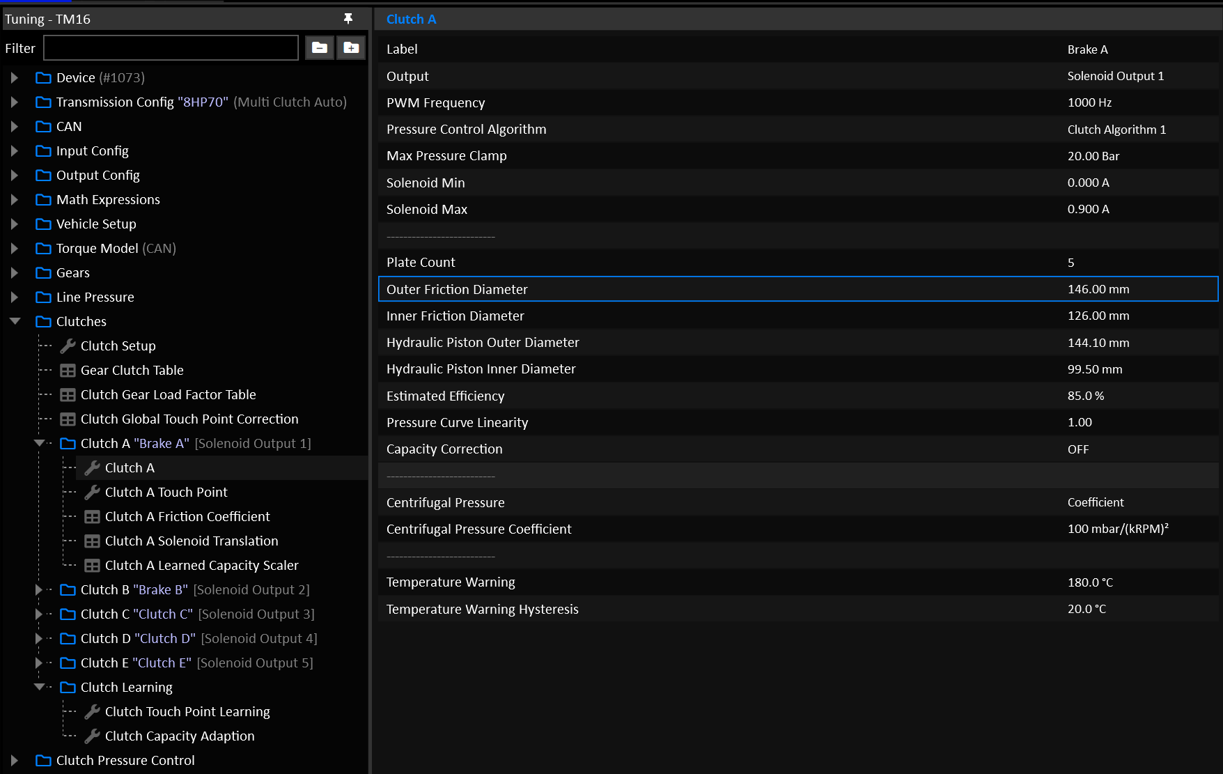
Clutch Geometry
Clutch geometry is taken into account in two directions:
- Calculating how much pressure to apply to hold a given torque.
- Calculating how much torque a given pressure can hold.
Plate Count
The number of friction plates in the clutch assembly. Aftermarket clutch kits often have increased plate counts, make sure to enter the correct number here.
Friction Diameters
The inner and outer diameters of the friction plate(s) should be entered accurately. Ideally these should be physically measured.
Hydraulic Piston Diameters
The hydraulic piston refers to the chamber that is filled with fluid in order to apply clamping force to the clutch. In the case of a fully open chamber without a shaft running through it (cylinder as opposed to a doughnut), an inner diameter of 0.0mm is valid.
Estimated Efficiency
Estimates the inefficiencies or mechanical losses involved in converting a given hydraulic pressure to a clamping torque capacity.
Typical Value: 85.0%
Pressure Curve Linearity
Bends the clutch’s Torque to Pressure translation into a non linear curve.
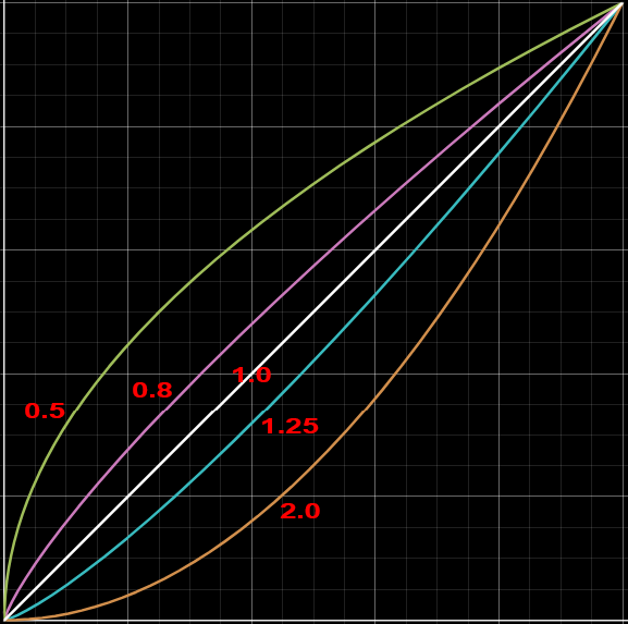
Typical Value: 1.00
Capacity Correction
Enables a table that allows the user to manipulate the final calculations.
In most cases this should NOT be used.
Typical Value: OFF
Clutch Friction Coefficient
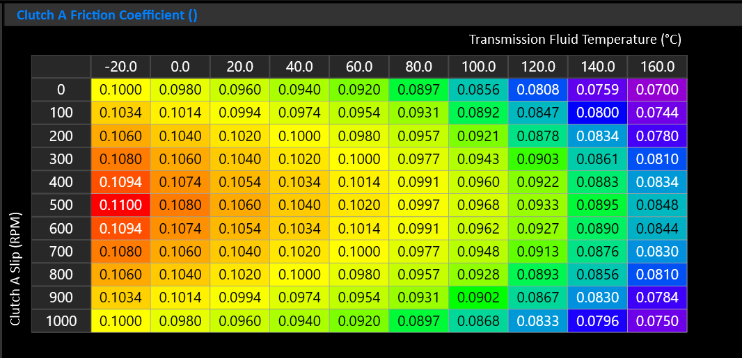
This table controls the frictional behavior of the clutch. Typically a wet clutch will have an increase in friction as it heats up with moderate slip, before falling back off as slip increases.
If you’re unsure, a generic table is provided that can be loaded in as a good starting point.
Centrifugal Pressure
Wet clutch drums spinning at speed generate centrifugal hydraulic pressure that acts on the piston independently of commanded pressure. At high drum speeds this can cause an offgoing clutch to partially engage even when you command only touch-point pressure.
On some transmissions dragging will be evident as a torque interruption or slip resistance during rev-matched downshifts. It may feel like the car is being pushed when the clutches should be fully slipping.
Select the mode used to calculate Clutch Centrifugal Pressure.
- Modelled = Clutch geometry based.
- Coefficient = Uses a coefficient that is independent of clutch geometry.
Modelled Centrifugal Pressure
When Clutch Centrifugal Pressure is in Modelled mode, the Clutch’s Centrifugal Pressure is calculated using the clutch geometry. Cancellation Efficiency represents how well the clutch resists the build up of centrifugal pressure.
- 0% = Full Modelled Centrifugal Pressure, maximum correction.
- 100% = No Modelled Centrifugal Pressure, no correction.
Centrifugal Pressure Coefficient
The coefficient compensates by subtracting from the total target pressure for the offgoing clutch.
- Start at 0 (disabled).
- Increase in steps of 20-30.
At 3000 RPM, each step of 10 removes appox. 0.09 bar of commanded pressure.
Typical Value: 0 or 100 - 200
Clutch Gear Load Factor
Not required for DCT Transmissions
Tip
This table is considered “Set & Forget”. It should be setup early on and left, rather than used as a tuning table.
Multi-clutch automatic transmissions use multiple clutches and brakes to create each gear. These elements do not share torque equally. Depending on the gear ratio and planetary gearset layout, one element may carry much more reaction torque than another. Each clutch will often have a different input torque applied to it depending on the combinations of clutches and gears also applied for a particular gear.
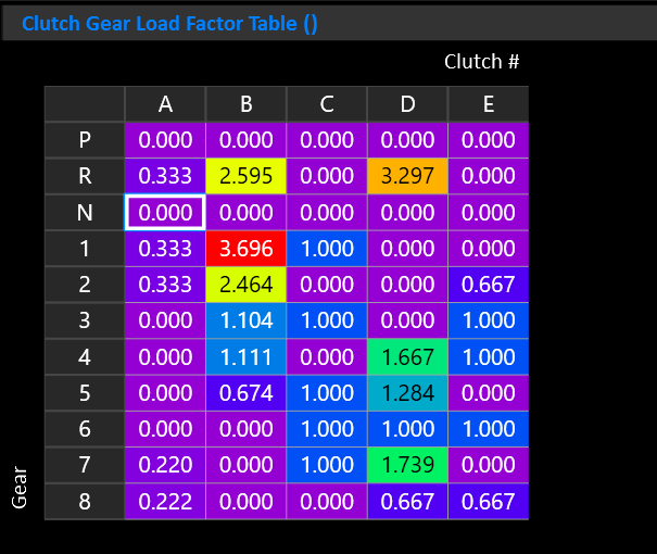
The Clutch Gear Load Factor table accounts for this internal torque multiplication on a per gear and per clutch basis.
This allows the TCM to estimate how much torque capacity each applied element needs in each gear.
Important
- X Axis must be “Clutch #”
- Y Axis must be “Gear”
- Z Axis is not used
The values in this table are not gear ratios or pressure multipliers. They are torque-capacity multipliers used before the torque-to-pressure calculation.
The resultant input torque for each clutch is shown by the “Clutch N Input Torque” runtime.
Important Notes:
- Load Factors can be calculated from the transmissions gear set.
- Only elements that are applied in a gear should have non-zero values. Elements that are released in that gear should be set to zero.
- Increasing a value will increase the calculated torque capacity requirement for that element in that gear, resulting in higher commanded pressure.
- Decreasing a value will reduce the calculated pressure requirement.
- If the value is too low, the clutch or brake may slip under load.
- If the value is too high, the shift or gear engagement may become harsh, inefficient, or create unnecessary clutch stress.
- It’s recommended to set each Clutch’s Learned Capacity Scaler Table Y axis of “Gear”. This allows the clutches to learn on a per-gear basis.
Clutch Pressure Control
The TCM needs to apply pressure to the clutch(s) in two main scenarios:
- In Gear (Active Clutch Pressure)
- During a shift
Other sub systems such as Takeup can takeover the clutch pressure control. They’re documented separately.
Active Clutch Pressure
The Active Clutch Pressure refers to the pressure applied to a clutch that is transmitting normal in-gear torque. The primary influencing factor on Active Clutch Pressure is Torque.
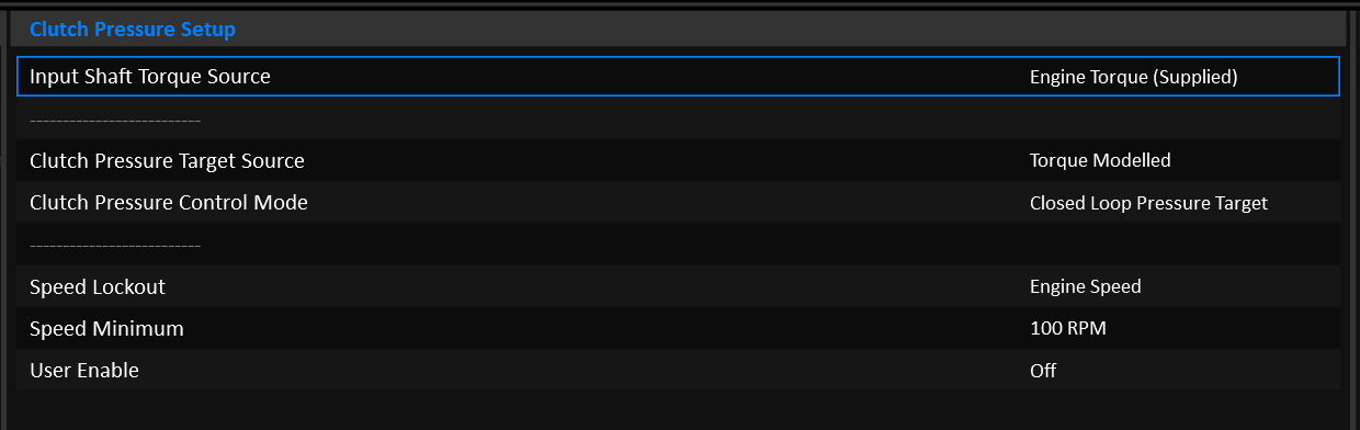
Input Shaft Torque Source
Torque based clutch pressure uses the Input Shaft Torque runtime for it’s calculations. The source of Input Shaft Torque can come from:
- Engine Torque (Supplied)
- Engine Torque (Available)
- Engine Torque (Supplied & Inertia Corrected)
Most setups would use
Engine Torque (Supplied).
Clutch Pressure Target Source
The pressure applied can be calculated in a number of ways:
- Torque Modelled
- User Defined
- Line Pressure Controlled
Tip
DCT Transmissions should almost always use Torque Modelled mode.
Target Source: Torque Modelled
---
title: Torque Modelled Clutch Pressure
---
graph LR;
  Prs(Clutch Pressure) -->|Bar| PID(PID)
  Tq(Input Shaft Torque) -->|Nm| TqCap{Sum: Required Torque Capacity}
  Clamp(Clamping Torque Margin) -->|Nm| TqCap
  TqCap -->|Nm| Geo(Clutch Model)
  Geo -->|Bar| Src{<strong>Clutch Pressure Target Source</strong>}
  Src -->|Bar| Sol(Solenoid Translation)
  Sol -->|Amps| PID
  PID --> |Amps| Curr[Solenoid Current]
  Src -->|Bar| PID
It is absolutely critical that the engine torque data is accurate.
Clutch Pressure is calculated using the Clutch’s geometry model. The pressure that comes out of the clutch model is intended to be the minimum pressure required to hold a given input torque, no more. The user can (and should) apply a Clamping Torque Margin on top of the Input Shaft Torque so that the clutch is commanded to hold slightly more torque and apply a slightly higher pressure as a result.
PID Control can be enabled if a Clutch Pressure Sensor is available.
For detailed information on how to setup the clutch model, see the Clutch Model documentation.
Target Source: User Defined
---
title: User Defined Clutch Pressure
---
graph LR;
  Prs(Clutch Pressure) -->|Bar| PID(PID)
  Tgt(Active Clutch Pressure Target) -->|Bar| TgtFnl{Target * Correction \+ Offset}
  Corr(Active Clutch Pressure Correction) -->|%| TgtFnl
  Offs(Active Clutch Pressure Offset) -->|Bar| TgtFnl
  TgtFnl -->|Bar| Src{<strong>Clutch Pressure Target Source</strong>}
  Src -->|Bar| Sol(Solenoid Translation)
  Sol -->|Amps| PID
  PID --> |Amps| Curr[Solenoid Current]
  Src -->|Bar| PID
In user defined mode, the Clutch Pressure Target simply comes from a Table. Optionally a Correction and Offset can be applied.
PID Control can be enabled if a Clutch Pressure Sensor is available.
Target Source: Line Pressure Controlled
---
title: Line Pressure Controlled Clutch Pressure
---
graph LR;
  LnPrs(Line Pressure) -->|Bar| Src{<strong>Clutch Pressure Target Source</strong>}

  PrsMax(Clutch Model: Max Pressure) --> |Bar| Sol(Solenoid Translation)
  Sol --> |Amps| Curr[Solenoid Current]
This mode is a special case for transmissions that simply expose all active clutches to full line pressure when in gear. This is the case for transmissions such as the ZF 8HP.
The Pressure Target and Solenoid Current are completely decoupled in this mode:
- The clutch solenoid is held at the current that achieves the maximum pressure (as configured in the Clutch Setup) according to it’s Solenoid Translation table.
- Line Pressure is copied into the
Active Clutch Pressureand Clutch # Pressure Target runtimes simply to give them something useful to display.
PID control cannot be used.
Shift Pressures
During a shift, the clutch pressure is fully modelled. No user defined pressure mode is available. The process of controlling a shift with user defined tables would put an enormous tuning burden on the end user that would require a lot of time to configure. The user can still tune a lot about how the shift feels, they just don’t have to worry about the actual pressures involved.
Calculating the pressure during a shift is very similar to when in gear, but the input torque will depend on weather the clutch is oncoming or offgoing, and the phase of the shift.
---
title: Torque Modelled Clutch Pressure
---
graph LR;
  Prs(Clutch Pressure) -->|Bar| PrsPid(Pressure PID)
  Tq(Input Shaft Torque) -->|Nm| ShtTq{Clutch/Phase/Slip Torque Manipulation}
  EngIn(Engine Inertia) -->|kg⋅m²| ShtTq
  EngSpdDt(Engine Speed Delta) -->|RPM/s| ShtTq
  GearSpd(Oncoming/Offgoing Gear Speeds) -->|RPM| ShtTq
  SlpTgt(Slip Target) -->|RPM| ShtTq
  Slip(Clutch Slip) -->|RPM| ShtTq
  ShTime(Shift Time Targets) -->|ms| ShtTq

  SlpTgt(Slip Target) -->|RPM| ShtPid
  Slip(Clutch Slip) -->|RPM| ShtPid
  ShtTq -->|Nm| ShtPid(Shift PID)
  ShtPid -->|Nm| TqFinal(Shift Torque)
  TqFinal -->|Nm| Geo(Clutch Model)
  PrsRate(Clutch Pressure Rate Limits) -->|Bar/s| Src
  Geo -->|Bar| Src{<strong>Clutch Pressure Target</strong>}
  Src -->|Bar| Sol(Solenoid Translation)
  Sol -->|Amps| PrsPid
  PrsPid --> |Amps| Curr[Solenoid Current]
  Src -->|Bar| PrsPid
It is absolutely critical that the engine torque data is accurate.
For detailed information on the shift phases, see the Multi-Clutch Shifting documentation.
For detailed information on how to setup the clutch model, see the Clutch Model documentation.
Clutch Touch Points
One of the most important things to setup on a new installation is the clutch touch points.
The touch point refers to the amount of pressure applied to the clutch before any meaningful torque capacity is applied.
- Below the touch point, the clutch is fully slipping.
- Above the touch point, the clutch is starting to hold torque.
The clutch’s torque capacity starts at the touch point. It’s effective pressure is it’s total pressure less it’s touch point. For example:
The user MUST find the touch point of each clutch. Failing to do so will result in poor drivability and shifting.
Touch Point Tuning
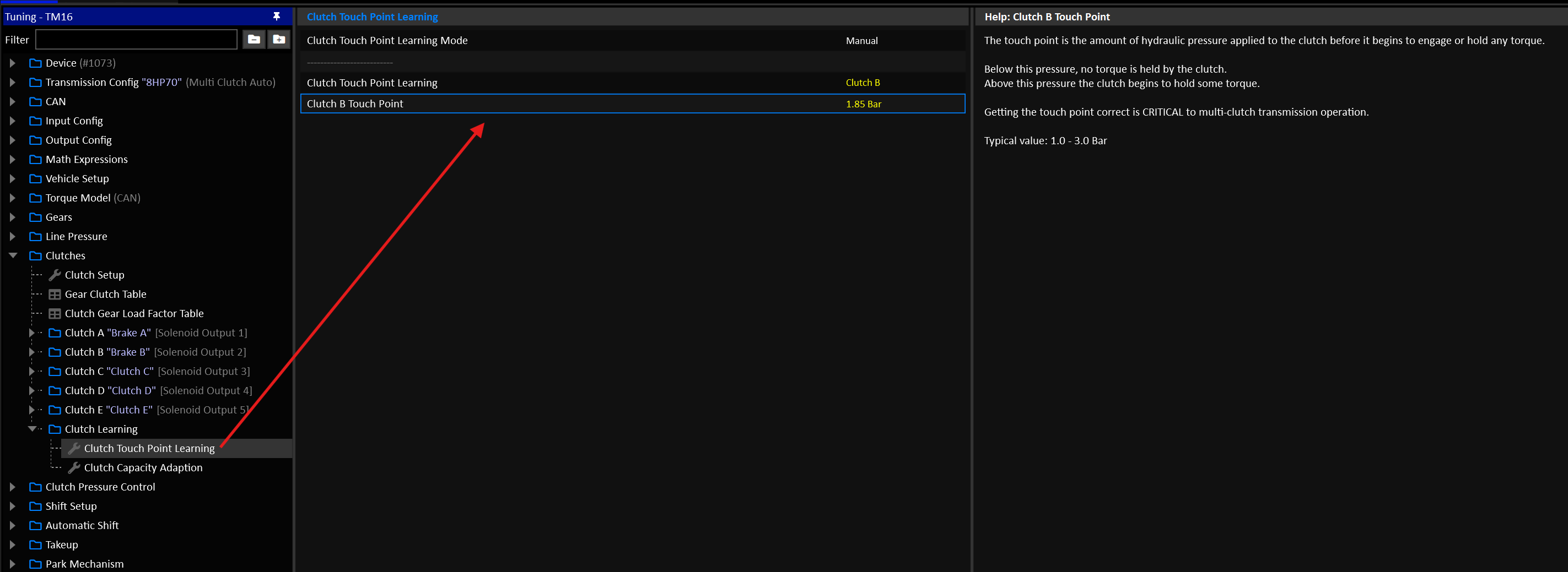
To find the touch points, the following condition must be met:
- Transmission Fluid Temperature: 60-90°C
- Gear: Neutral
- Brake: ON
- Input Shaft Speed: 500-2000 RPM
- Output Shaft Speed: 0 RPM
Automated Touch Point Learning
You can put the TCM into automated learning mode for a given clutch. For this system to work, the engine idle speed needs to be very stable. On engines where the idle speed is rough (large camshafts etc), it’s likely better to do manually.
Set the clutch to be tested and the TCM will engage all relevant surrounding clutches that would result in a driving gear using the clutch in question. It will then slowly ramp the clutch pressure up and look for a dip in Input Shaft Speed. This process will be repeated 5 times and the result of those tests will be averaged to find the final touch point.
The test will exit if the entry conditions are no longer met, Eg: The user releases the brake.
If the automated test errors out, an erroneous value may be applied to the clutch’s touch point and the test should be run again.
Manual Touch Point Learning
- Set the clutch to be tested and the TCM will engage all relevant surrounding clutches that would result in a driving gear using the clutch in question.
- Slowly increase the Touch Point Setting and watch for the moment where the clutch starts to drag on the input shaft.
- The actual touch point will be a little before this, where any more pressure results in noticeable drag.
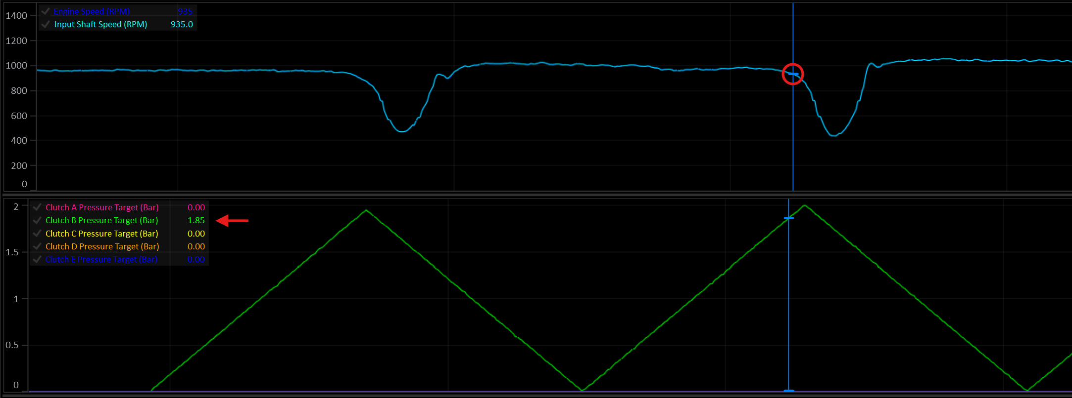
In this example, as Clutch B reaches ~1.85 Bar, the Input Shaft Speed begins to noticeably dip as drag is applied to the input shaft. The actual touch point, before the clutch begins to drag on the input shaft, would be slightly before that at about 1.75 Bar.
Touch Point Correction
A correction scaler can be applied on either a global or per-clutch level. If you find that at varying fluid temperatures the touch points need adjustment, these corrections can address that.
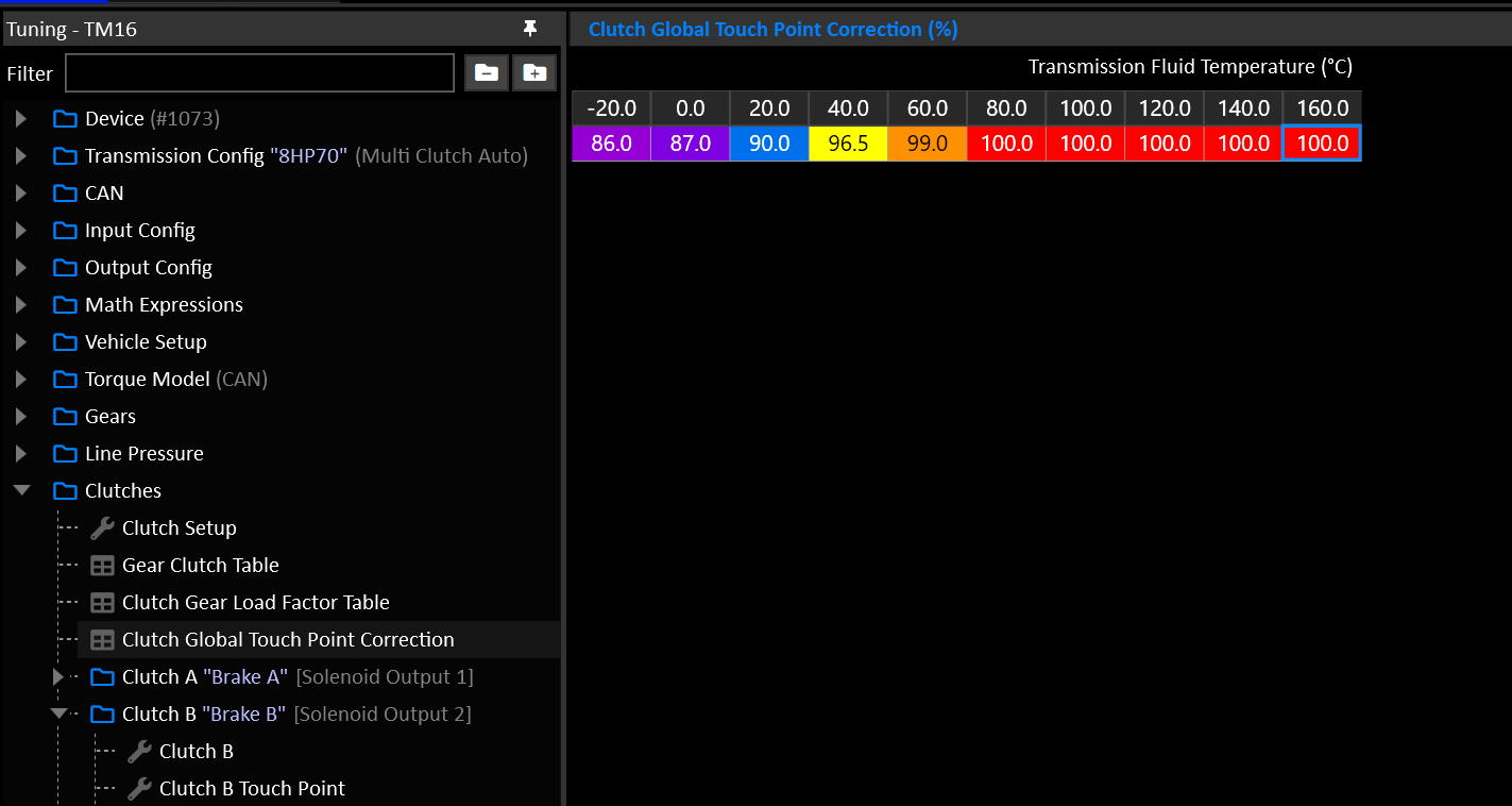
Here, at 20°C a nominal Touch Point of 1.75 Bar would become 1.57 Bar.
Data Logging
The TCM has a built-in data logger that records selected channels to eMMC memory.
| Logging Specs | |
|---|---|
| Max Capacity | 8GB |
| Max Channels | 500 |
| Max Frequency | 1000 Hz |
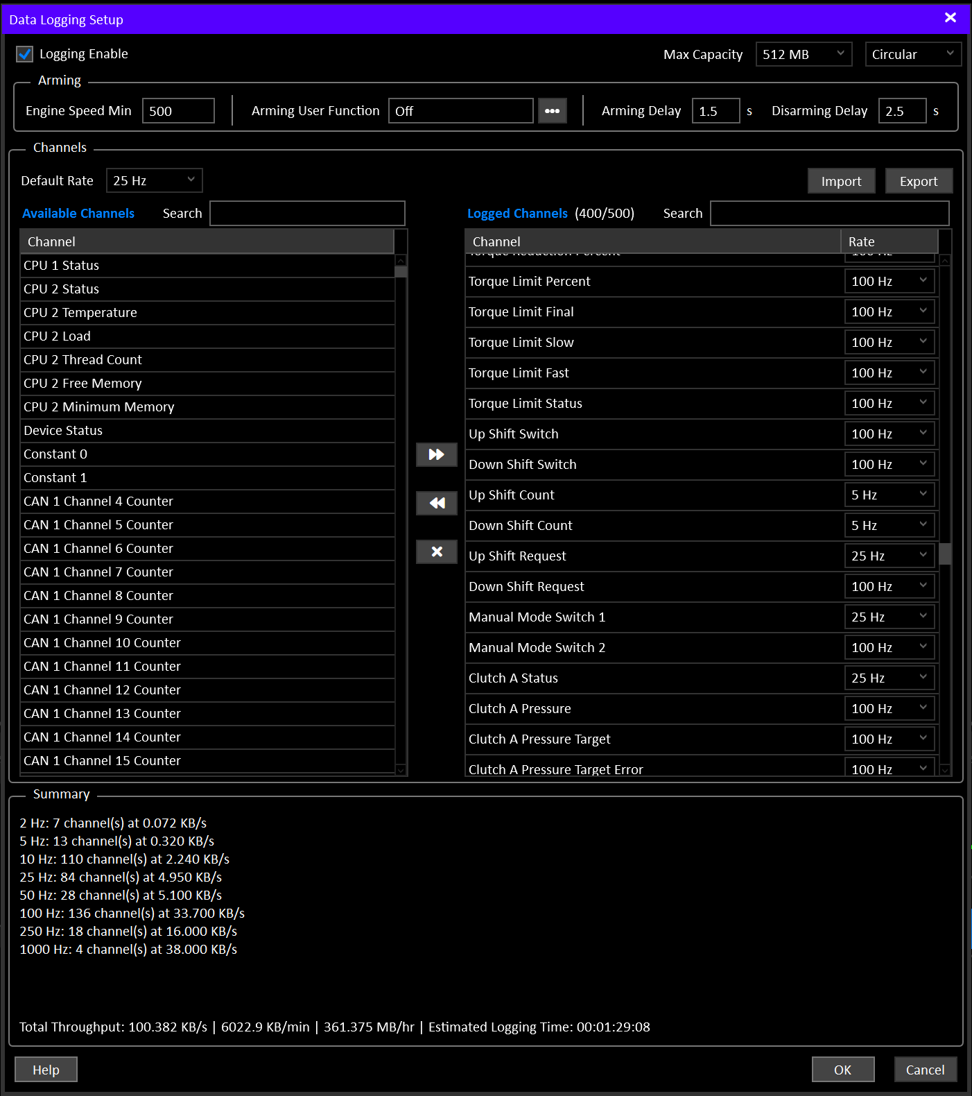
Logging Enable must be ON in Data Logging Setup, and at least one channel must be selected. With Logging Enable OFF the logger is completely inactive and ignores all arming conditions.
Sessions
Each time the logger arms, a new recording session starts. Everything recorded until it disarms belongs to that session.
A single download can contain many sessions (e.g. several on/off cycles across a track day). When the log is downloaded, all sessions are joined together in time order, with a marker at each session boundary so they can still be told apart on a chart.
Channels
A maximum of 500 channels can be selected for logging.
Each channel can be recorded at any of the following frequencies:
- 1 Hz
- 2 Hz
- 5 Hz
- 10 Hz
- 25 Hz
- 50 Hz
- 100 Hz
- 250 Hz
- 500 Hz
- 1000 Hz
Each frequency option can have a maximum of 255 channels assigned.
For Example: You can choose 255 channels at 100 Hz and 100 Channels at 50Hz, but you cannot choose 355 channels at 100 Hz.
Channels are moved from Available Channels into Logged Channels, where each one is assigned a rate. Default Rate sets the rate newly added channels start at, and the rate of several channels can be changed at once from the right-click menu. The setup screen will not allow either channel limit to be exceeded.
A channel list (channels and rates) can be saved to a file and reloaded with Export and Import. This is useful for keeping a few standard setups (e.g. “track day”, “dyno session”) and switching between them, or between vehicles.
Tip
To maximize memory usage, only log channels as fast as necessary.
- Slow moving signals like temperature’s only need to be 5-25 Hz
- Fast moving signals like clutch pressure benefit from being faster (100-250 Hz)
Capacity
The maximum capacity of the logging memory is a little under 8GB. Some space is reserved for config storage and other system functions. The memory capacity used by the Data Logging system can be set from 128MB to 8GB. Downloading a log from a fully filled 8GB capacity will take a very long time (over an hour), so it can be useful to limit the maximum logging capacity to make it more practical.
One-Shot / Circular Mode
Data logging can be used in two distinct modes:
- One-Shot: Once full, logging stops. No new data is recorded until the memory is erased.
- Circular: Once full, the oldest data will be overwritten with new data.
Circular mode is extremely useful for set and forget logging. You can enable it and leave it running. In the event that something happens that you want to review, the most recent data will always be available.
Limiting the total capacity in circular mode makes periodic log downloads more manageable.
Example:
A typical “full coverage” logging set might have 400 channels in it. Setting the capacity to 512MB might result in about 1.5 hours of total logging time, which will only take a couple of minutes to download in the event that you want to review it.
Partial Sessions
In circular mode, when the logging capacity is reached and a logging session is still recording, writing wraps back to the start of the memory, overwriting the oldest session data. A session that gets overwritten will loose it’s channel information first, followed by it’s oldest data. If the user has not changed the logging channel selection or frequencies, the partially overwritten data can still be decoded as it’s channel layout will match the newer sessions. If the user changes the channel or frequency layout, the entire old session will be lost.
Note
Switching from Circular back to One-Shot after the log has wrapped will erase the log. Once data has been overwritten in a loop, there is no single continuous recording left to keep.
Estimated Logging Time
Data Logging Setup shows a live Estimated Logging Time for the selected channels and rates. This is the figure to check before a recording session.
As a guide to the scale involved, the table below uses 10 channels at a single rate, assuming a typical mix of channel sizes:
| Rate | Data rate | Fills 1 GB in | Fills 8 GB in |
|---|---|---|---|
| 1 Hz | ~40 B/s | ~310 days | ~6.8 years |
| 2 Hz | ~80 B/s | ~155 days | ~3.4 years |
| 5 Hz | ~200 B/s | ~62 days | ~1.4 years |
| 10 Hz | ~400 B/s | ~31 days | ~249 days |
| 25 Hz | ~1.0 KB/s | ~12.4 days | ~99 days |
| 50 Hz | ~2.0 KB/s | ~6.2 days | ~50 days |
| 100 Hz | ~4.0 KB/s | ~3.1 days | ~25 days |
| 250 Hz | ~10 KB/s | ~30 hours | ~10 days |
| 500 Hz | ~20 KB/s | ~15 hours | ~5 days |
| 1000 Hz | ~40 KB/s | ~7.5 hours | ~2.5 days |
Logging 10 channels at every rate at once (100 channels) comes to roughly 76 KB/s, which fills 1 GB in around 4 hours and 8 GB in around 31 hours. Choosing a sensible rate for each channel is the biggest factor in how long a recording lasts.
Arming / Disarming
The logger can be armed in a number of ways:
| Condition | Description |
|---|---|
| Logging Enable Switch | When ON, the logger will run as long as Engine Speed Min is exceeded. |
| Arming User Function | The logger will run when the selected User Function is ON and Engine Speed Min is exceeded. |
Info
If Engine Speed Min is greater than zero, it will lockout the logger until it’s exceeded.
If the Logging Enable Switch is OFF AND Arming User Function is OFF, the logger will enable when Engine Speed Min is exceeded. This is the absolute minimum required arming condition.
Arming / Disarming Delays
- Arming Delay: Delays arming until the arming conditions have been true for the delay time (0-25 seconds).
- Disarming Delay: Delays disarming until the arming conditions have false for the delay time (0-25 seconds).
Downloading
Logging is paused while a log is downloaded, and resumes automatically afterwards if the logger is still armed. Logging and downloading cannot happen at the same time.
Before downloading, the number of sessions recorded since the last erase and how full the memory is are shown. If nothing has been recorded since the last erase, Download and Erase are unavailable.
Downloads run over Ethernet at roughly 1.5 MB/s. As a guide, a full 1 GB log takes around 12 minutes to download, and a full 8 GB log around an hour and a half.
Once downloaded, a Log Details screen is shown before the log file is saved. Vehicle and Transmission are filled in from the Device Label and Transmission Label settings, and the remaining details (driver, venue, weather, notes, etc.) can be added.
Erasing
Erasing clears the entire log. Logging is paused and resumed automatically around the erase, and confirmation is requested if the log contains data.
Log Markers
When configured, the Log Marker Switch input can be used to mark moments in time in the logged data.
On the rising edge of the switch, the next single batch of log data will be marked. This mark will show up in the plotted data as a dotted blue line.
Power Loss Behavior
The logging system commits data from RAM to permanent memory approximately once per second. The TCM should be wired to be in control of it’s own power supply. This allows it to shutdown the data logging system and ensure that any pending data sitting in RAM is committed before powering itself down.
In the event of an unexpected power loss, any data still in RAM will be lost. This is typically ~1 second worth of data.
Drive Modes
Drive Modes refer to the main transmission states such as Park, Reverse, Neutral, and Drive (Auto, Sport, Manual). Selection of the desired drive mode can be achieved a variety of ways including:
- CAN bus shifter (preset or custom)
- Analog shifter position
- Digital shifter position matrix
- Switches or buttons
- Up Shift & Down Shift switches
- Combinations of the above
Drive Mode Input Priorities
Drive mode input sources have fixed priorities. This allows them to be used in conjunction with one-another with predictable results. Inputs with higher priority will override inputs with lower priority.
| Priority | Input Source |
|---|---|
| 1 (Highest) | Park Request Switch |
| 2 | Neutral Request Switch |
| 3 | Shifter Position (Park / Reverse / Neutral) |
| 4 | Reverse Request Switch |
| 5 | Manual Switch |
| 6 | Sport Switch |
| 7 | Drive Switch |
| 8 | Shifter Position (Drive / Sport / Manual) |
| 9 | Up Shift Switch |
| 10 (Lowest) | Down Shift Switch |
Example: If the shifter is in the Neutral position, but the Park Request Switch is enabled and in the active (ON) state, the transmission will remain in Park until the Park Request Switch becomes inactive (OFF) because the Park Switch has higher priority than the Shifter Position input.
Manual Override
Manual Override puts the TCM into Manual while Drive or Sport is selected, without the driver having to select Manual. It is applied after the input priorities above, and can come from the Manual Override Switch or from the Up Shift & Down Shift switches.
While the Manual Switch has selected Manual, the Manual Override inputs have no effect.
Manual Override Switch
While the Manual Override Switch is ON, selecting Drive or Sport gives Manual instead. Turning the switch OFF returns the TCM to Drive or Sport.
This works however Drive or Sport is selected (shifter, Drive or Sport Switch, or holding Up Shift from Neutral), and whether the switch is turned ON before or after Drive or Sport is selected.
Example: The
Manual Override Switchis already ON when the TCM starts up. Selecting Drive from Neutral goes straight to Manual. Turning the switch OFF then changes to Drive.
Selecting Park, Reverse or Neutral ends the override. If the switch is still ON when Drive or Sport is selected again, the TCM goes back to Manual.
Up / Down Shift Switches
Set Up / Down Shift Switch Behaviour (Automatic Shift > Auto Shift Setup) to Manual Override to have an Up Shift or Down Shift press in Drive or Sport change to Manual. The press also requests the shift.
The TCM returns to Drive or Sport when any of the following happens:
- Manual Override Timeout: No Up Shift or Down Shift press has been made for this time. Each press restarts the timer. Set to 0 to stay in Manual until cancelled.
- The
Manual Switchis pressed. - Park, Reverse or Neutral is selected.
If the Manual Override Switch is also ON, the TCM stays in Manual until that switch is turned OFF.
Cancelling with the Manual Switch
Pressing the Manual Switch only cancels the override when the switch is connected to a TCM input. It doesn’t work when the Manual Switch comes from CAN or a script.
Engine Torque
Important
Accurate engine torque modelling is critical for transmission performance.
Engine Inertia
Engine inertia is used to calculate the clutch torque required to sync the engine speed during a shift. It also informs the rev-match torque calculation.
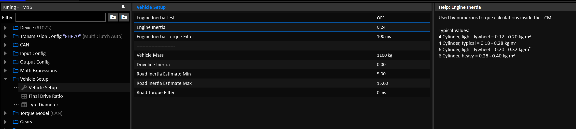
| Engine / configuration | Typical Inertia (kg·m²) |
|---|---|
| Small 4-cyl light flywheel | 0.12 – 0.20 |
| Typical 4-cyl production | 0.18 – 0.28 |
| Performance 6-cyl (light flywheel) | 0.20 – 0.32 |
| Heavier 6-cyl / street flywheel | 0.28 – 0.40 |
| Big heavy flywheel / truck | 0.40 – 0.70+ |
Launch Control
Warning
Launch Control is a motorsport orientated function can lead to transmission and/or other driveline component damage if not used correctly.
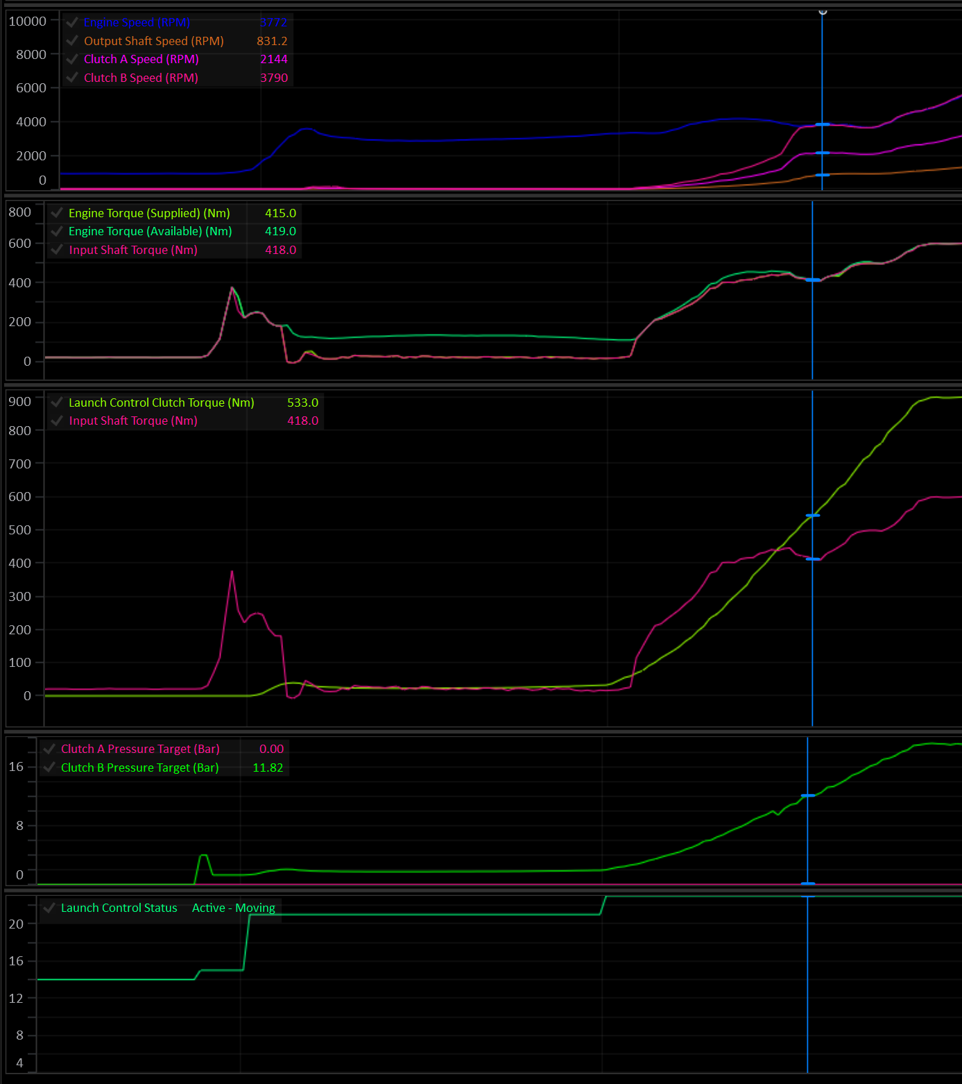
Overview
Launch Control can be configured in a variety of way depending on the desired control outcome.
Launch control can be configured to:
- Control clutch torque and clutch torque rate.
- Generate an Engine Speed Target to be sent to the engine.
- Generate a torque limit to to be sent to the engine.
There are 5 main states/phases the Launch system can be in:
| State | Meaning |
|---|---|
| Disarmed | Off, or arming conditions not currently met. |
| Armed | Arming conditions met, waiting for launch lockouts to clear. |
| Static | Car stationary, launch active. Clutch is typically held open/slipping to a torque target. |
| Preload | (Optional) Clutch is pre-loaded to a torque target for a fixed dwell time before the final dump. |
| Moving | Clutch torque is actively controlled through the launch. Ends when a disarm condition is met. |
Set Enable to ON in Launch Control Setup to turn Launch Control on. While disabled, it has no effect on clutch pressure, engine speed target or torque limit.
Clutch Control
The primary function of Launch Control is to override the clutch pressure by generating a clutch torque request.
Clutch Control is enabled in Launch Control Setup.
Launch Control never engages a clutch that isn’t already part of the currently selected gear. It can only override the pressure target of a clutch the TCM has already activated for that gear. It cannot bring in an extra clutch on its own.
Launch Control Clutch Select
Care should be taken to ensure the Launch Control Clutch Select table is set up correctly. In most case the table will be identical to the Takeup Clutch Select table.
Important
The Clutch Select table’s X axis MUST be Clutch #.
The table is re-evaluated each time the system re-arms into the Static phase. This allows the table’s Y axis to be another channel such as Gear.
When Clutch Control is disabled, Launch Control does not touch clutch pressure at all — only the engine RPM target / torque limit outputs (if enabled) are active.
Arming & Disarming
Arming
The system arms when every configured arming condition is simultaneously true. Each condition is independently optional (Eg: 0 = OFF). Enable only the conditions relevant to your application.
At least one condition must be configured, or the system will report “Disarmed - No Arming Config” and never arm.
| Condition | Enable via | Threshold |
|---|---|---|
| Launch Switch | Launch Arming Switch = ON | Launch Arming Switch = ON |
| Brake Switch | Brake Switch Arming = ON | Brake Switch 1 = ON |
| Brake Pressure | Arming Brake Pressure Minimum > 0 | Brake Pressure Front > Threshold |
| Transbrake Switch | Transbrake Switch Arming = ON | Transbrake Switch= ON |
| User Function | Arming User Function ≠ Off | User Function # Status = ON |
Static → Moving
Releasing any configured arming condition while in Static or Preload is what triggers the transition into Preload/Moving.
Lockouts (Armed → Static)
Once armed, the system waits for all configured lockouts to clear before entering the Static phase.
At least one lockout must be configured, or the system will report “Lockout - No Lockout Config” and will not enter Static.
| Lockout | Enable via | Condition to clear |
|---|---|---|
| Gear | Always active | Gear ≥ 1st |
| Clutch By Wire | Always active | CBW must not be active |
| Pedal/throttle position | Static Lockout Pedal/Throttle Position > 0 | Pedal Position* ≥ Threshold |
| Output Shaft Speed | Static Lockout Output Shaft Speed > 0 | Output Shaft Speed < Threshold |
| Drive Speed | Static Lockout Drive Speed > 0 | Drive Speed < Threshold |
| Engine speed | Static Lockout Engine Speed > 0 | Engine Speed > Threshold |
| User Function | Static Lockout User Function ≠ Off | User Function # Status = ON |
* If
Pedal Positioninput is not configured,Throttle Positionis used.
Disarming (Static / Preload / Moving → Disarmed)
While active, the system aborts back to Disarmed immediately if:
- The TCM begins a shift.
- The gear selector leaves Drive/Manual (enters Park/Neutral/Reverse)
- Any one of the following (each optional) stays true for longer than the
Disarming Time(ms):
| Disarm condition | Enable via | Trips when |
|---|---|---|
| Pedal/Throttle Position | Disarming Pedal/Throttle Position > 0 | Pedal Position* < Threshold |
| Output Shaft Speed | Disarming Output Shaft Speed > 0 | Output Shaft Speed > Threshold |
| Drive Speed | Disarming Drive Speed > 0 | Drive Speed > Threshold |
| Engine Speed | Disarming Engine Speed > 0 | Engine Speed < Threshold |
| Clutch Slip | Disarming Clutch Slip > -1000 | Clutch Slip < Threshold (clutch locked) |
* If
Pedal Positioninput is not configured,Throttle Positionis used.
If no disarming condition is configured, the system disarms immediately (nothing is holding it active).
Active Launch Phases
Static
In the Static phase the car is stationary with the engine is held at the desired launch RPM (this is to be controlled by the engine ECU). The TCM can generate a torque limit and/or Engine Speed Target to be issued to the engine via CAN.
Static Clutch Torque: Typically the clutch is either fully open or a small amount of torque is applied for the engine to load up against.
Caution
Applying clutch torque during static phase will lead to very high clutch temperatures and should be treated with caution.
Preload (optional)
Enabled when Preload Stage = ON in Launch Control Setup.
Preload is a dwell phase between Static and Moving where the clutch can be held at a preload torque target for a calibrated time, before the final dump.
It can be triggered in three ways:
| Trigger | Enable via | Behaviour |
|---|---|---|
| Auto | Preload Stage = ON, Preload User Enable = OFF, Preload Switch = OFF | Entered automatically the instant the arming condition is released. |
| Preload Switch | Preload Switch = ON | Entered as soon as Launch Preload Switch = ON. Can be requested before the arming condition is released, to preload ahead of the Moving phase. |
| Preload User Enable | Preload User Enable ≠ OFF | Entered as soon as User Function # Status = ON. Can be requested before the arming condition is released, to preload ahead of the Moving phase. |
Preload → Moving
- Preload will exit to Moving when
Launch Control Preload Timetable value expires, orMax Preload Timeexpires. - If Preload was entered manually (User Function or Preload Switch) rather than automatically, releasing the arming condition while still in Preload will cut it short and transition immediately to Moving.
Preload Clutch Torque: Typically, a small amount of torque is applied for the engine to load up against. The clutch torque rate is relatively slow so the engine doesn’t suddenly get dragged down.
Example:
- The driver arms launch with the
Launch Switchand enters Static. - A generous but not excessive time is entered into the Preload Time table (and Max Preload Time).
- Moments before launching the
Preload Switchis pressed and the system enters Preload. - Clutch pressure is ramped up & engine torque increases.
- Before the
Launch Preload Timeexpires, theLaunch Switchis released at the exact moment the driver wishes to launch. - The system then enters the Moving phase and ramps the clutch up to full lock torque.
In this scenario, the clutch can be loaded before launching, clutch temperature is minimised, and the driver is still in full control of the moment of launch.
Moving
During the moving phase, clutch torque is ramped up to full lock torque at a controlled rate.
Moving Clutch Torque: The final clutch torque should result in the clutch being fully locked. In a properly modelled system, the clutch will lock when it’s applied torque meets or exceeds the Input Shaft Torque. In a multi-clutch transmission with gear clutch load factors other than 1.0, this may vary and should be considered.
Moving Clutch Torque Rate: Clutch torque should be ramped in fast enough to minimise slip and engine flaring, while not dragging the engine speed down.
Tip
Most of the fine tuning time will be spent dialing in a suitable Moving Clutch Torque Rate.
Per-Phase Calibration Tables
Each of Static / Preload / Moving phases has its own set of tables. Torque Limits are enabled per-phase.
| Output | Enable via (per phase) | Table(s) |
|---|---|---|
| Engine Speed Target | Engine Speed Target Tables = ON (applies to all 3 phases) | Static/Preload/Moving Engine Speed Target |
| Engine Torque Limit | Static/Preload/Moving Torque Limit = ON | Static/Preload/Moving Torque Limit |
| Clutch Torque | Clutch Control = ON (applies to all 3 phases) | Static/Preload/Moving Clutch Torque |
| Clutch Torque Rate | Clutch Control = ON (applies to all 3 phases) | Static/Preload/Moving Clutch Torque Rate |
A phase’s torque limit is only applied while that phase is active. It’s released as soon as Launch Control moves to a phase without one, so a limit is never carried over from an earlier phase.
Runtime Channels
The following runtime channels are generated by the Launch control system:
- Launch Control Status (see Launch Control Status enumeration)
- Launch Control Engine Speed Target
- Launch Control Torque Limit
- Launch Control Clutch Torque
- Launch Control Static Time
- Launch Control Preload Time
- Launch Control Moving Time
Launch Control Status reports the current phase, or which arming condition or lockout is being waited on, which makes it the first channel to check when Launch Control won’t activate. The Static, Preload and Moving Time channels record how long each phase of the most recent launch took, for review after the run.
Interaction with Other Systems
Caution
Care should be taken to ensure other system lockouts are configured, in particular: Takeup.
- Transbrake: Transbrake clutches are unconditionally part of the active clutch set while held; Launch Control can overlay pressure on them like any other active clutch but never adds to the set itself.
- Takeup: If Takeup’s own
Launch Control Lockoutoption is set, Takeup control locks itself out whenever Launch Control is active (Static/Preload/Moving), so the two won’t fight over clutch pressure. - Clutch-By-Wire (CBW): An active CBW request blocks Launch Control from ever reaching Static (see lockout table above).
Multi-Clutch Shifting
Shifting on multi-clutch transmissions happens over 4 phase:
- Fill
- Torque Transfer
- Inertial Sync
- Lock
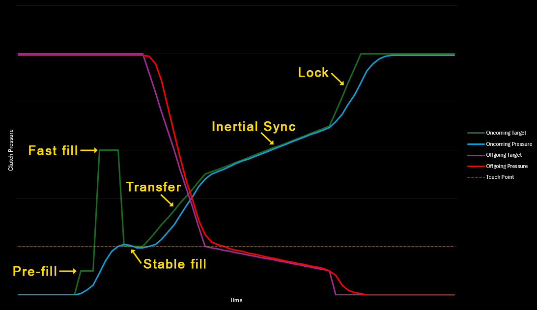
A simplified representation of the clutch pressures during the 4 shift phases.
The TCM will calculate all required clutch pressures based on supplied and available engine torque. As long as the clutch geometry is configured reasonably and the torque data from the engine is accurate, there’s very little tuning required.
It is absolutely critical that the engine torque data is accurate.
For detailed information on how the TCM converts torque to clutch pressure, see this section on Shift Pressures.
For detailed information on how to setup the clutch model, see the Clutch Model documentation.
Line Pressure
Caution
DO NOT try to tune the shifting on a multi-clutch transmission by manipulating the Line Pressure.
Line Pressure should be sufficient to supply all the pressure the clutches need during a shift, but the clutches should control their own pressures.
Clutch pressure can be considered a minimum value for the Line Pressure Target.
Some transmissions will require the Line Pressure to be set very high for the duration of a shift, giving maximum flow control to the clutch solenoids.
Depending on the transmission in question, setting the Line Pressure to “Downstream Pressure Offset” mode can simplify this process.
Fill Phase
Any clutch that is disengaged will have it’s pressure fully bled off. The job of the fill phase is simply to ensure that the oncoming clutch pressure chamber is filled with fluid so that it can operate as fast as possible once the shift actually starts.
Generally, the clutch pressure at the end of the Fill phase will be the clutch’s touch point pressure. The Fill phase is not intended to apply any meaningful clutch pressure.
Unlike the rest of the shift phases, the fill phase doesn’t use torque, it is purely pressure based.
The Fill phase is broken into 3 sub phases:
- Pre-Fill
- Fast Fill
- Stable Fill
The amount of time spent in each phase is limited by the Total Fill Time table and the phase order.
Example:
- Pre-fill = 20ms
- Fast fill = 40ms
- Total fill time = 100ms
Stable fill = 100 - (20 + 40) = 40ms
Setting a fill phase time to zero will result in that phase being skipped. It’s perfectly valid in many cases to skip the Pre-fill or the Fast Fill phase. It’s also common for high torque, high speed shifts to consist of only the Fast-Fill phase. In this case, the Pre-fill Time would be 0 and the Fast Fill Time would take up the entire Total Fill Time.
Regardless of the Pre-fill and Fast Fill times, the Fill phase will always exit once the Total Fill Time has elapsed.
Pre-Fill
The Pre-fill phase simply opens the clutch pressure solenoid at the very start of the shift. The specified pressure is absolute and disregards the touch point.
Pre-fill pressure does not usually exceed the touch point pressure.
Typical Pressure: 0.5 - 1.5 Bar Typical Time: 0-100ms
Setting the
Pre-Fill Timeto 0 will skip the Pre-fill phase.
Fast Fill
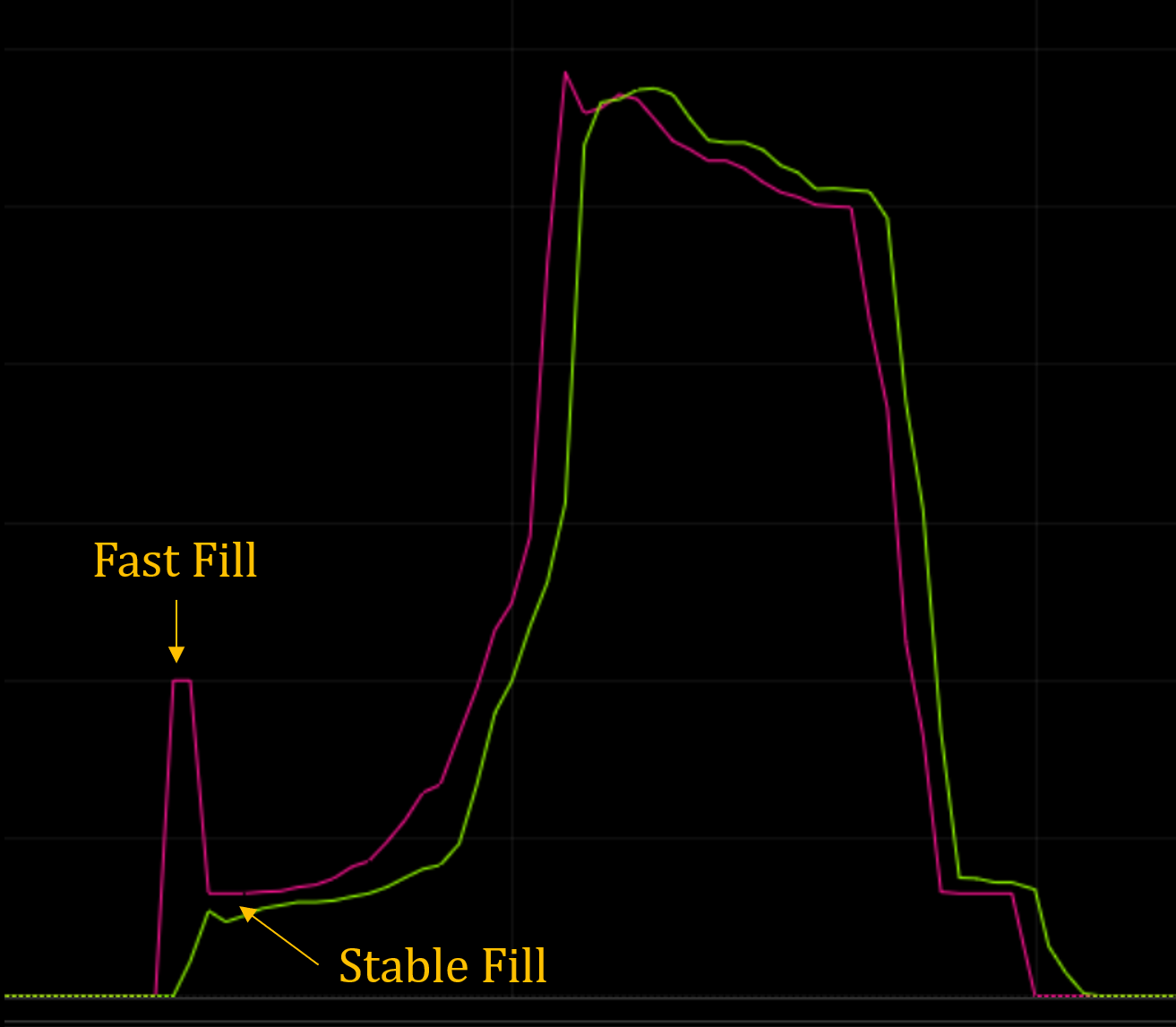
During Fast Fill, the clutch pressure solenoid is driven very high for a short period. The intention is to allow a fast in-rush of fluid to fill the clutch chamber as fast as possible.
Caution
A correctly configured combination of Fast Fill Pressure and Fast Fill Time should result in the actual pressure ramping up very quickly to, but never in excess of the touch point.
Typical Pressure: 3.0 - 5.0 Bar Typical Time: 20-50ms
Stable Fill
After the Pre-fill and Fast Fill phases are complete, any remaining Fill Time will be spent in the Stable Fill phase.
The pressure specified during Stable Fill is an offset of the clutch’s touch point pressure.
Example:
- Touch Point = 1.3 Bar.
- Stable Fill Pressure Offset = -0.1 Bar.
Stable Fill Pressure = 1.3 + -0.1 = 1.2 Bar.
Typical Pressure Offset: 0.0 Bar (Settle on the Touch Point)
Torque Transfer Phase
The Torque transfer phase begins the process of transferring supplied engine torque over to the oncoming clutch. In most cases, the oncoming clutch will still be fully slipping by the end of the phase, but it will be holding most of if not all the torque.
Up Shift & Overrun Down Shift
Torque is transferred to the oncoming clutch while the offgoing clutch is mostly released. By the end of the phase, the oncoming clutch will be carrying all the torque, but it will still be fully slipping at the offgoing gear speed. It’s the Inertial Sync phase’s job to reduce the slip to zero.
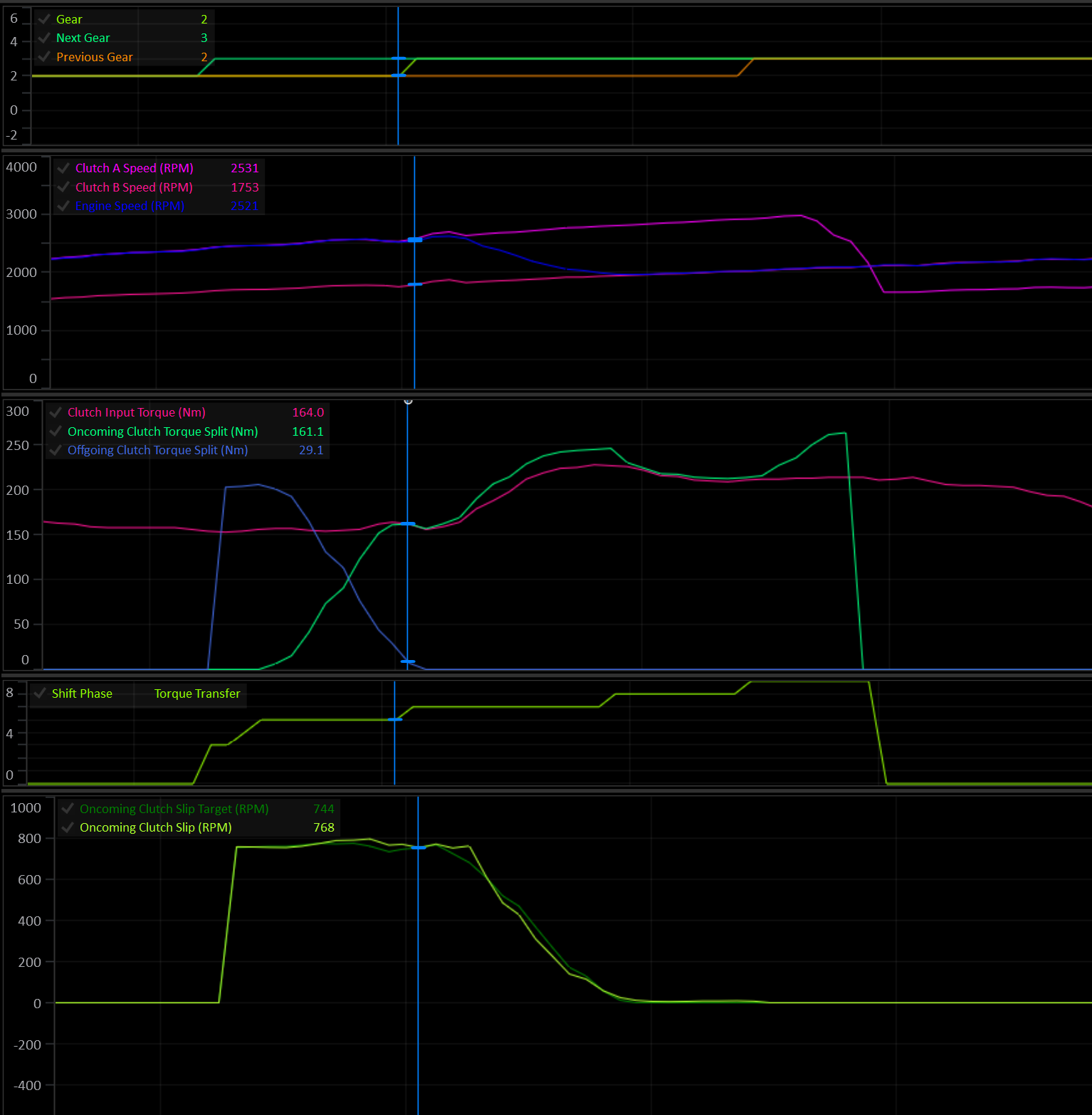
Note the engine speed is still matching Clutch A (offgoing) at the end of the transfer phase.
Driven Down Shift
During a driven down shift, the offgoing clutch’s torque capacity is reduced to deliberately introduce a controlled amount of slip that will bring the Input Shaft Speed up to the ongoing gear speed. As the clutch slip approaches zero, the oncoming clutch is ramped in to catch the input load, while the offgoing clutch is tapered out.
By the end of the Transfer phase the oncoming clutch slip should be near zero.
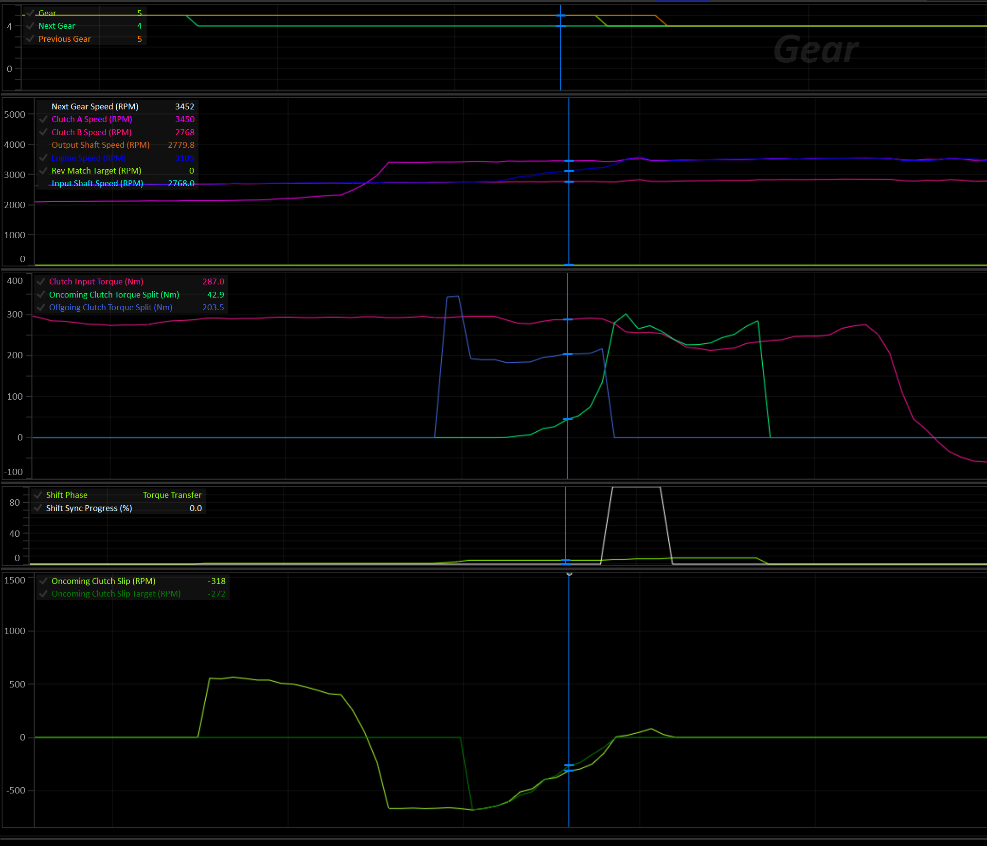
Driven Down Shift with ideal speed synchronization.
Down Shift Rev Match
During a rev match, both the offgoing and oncoming clutch are reduced to zero torque capacity. They will both settle on their touch points, allowing the engine to freely rev.
As the oncoming slip approaches zero, the oncoming clutch is ramped in to catch the input torque load.
Fast Fill During Transfer
When enabled, the Fast fill (and stable fill) phases are merged into the Torque Transfer phase. Both the transfer pressure and the fast/stable fill pressure are calculated at once. The highest of two is applied to the clutch.
This results in shorter shift times and faster pressure rates as the transfer pressure will simply take over as soon as it exceeds the fill pressure.
During fast shifts, the drop back to stable fill pressure can be effectively skipped.
Pre-fill always happens first if it’s time is non-zero.
Inertial Sync Phase
During this phase, clutch slip is reduced to near zero and the Input Shaft Speed is synced to the oncoming gear speed. Additional torque capacity is applied to the oncoming clutch to achieve this.
The engine’s inertia and torque is considered when calculating how much torque to apply to control the slip.
At high input torque, prolonged sync times will result in increased clutch heat and wear.
The main “Gear” runtime will change to the next gear at the start of the Inertial Sync phase.
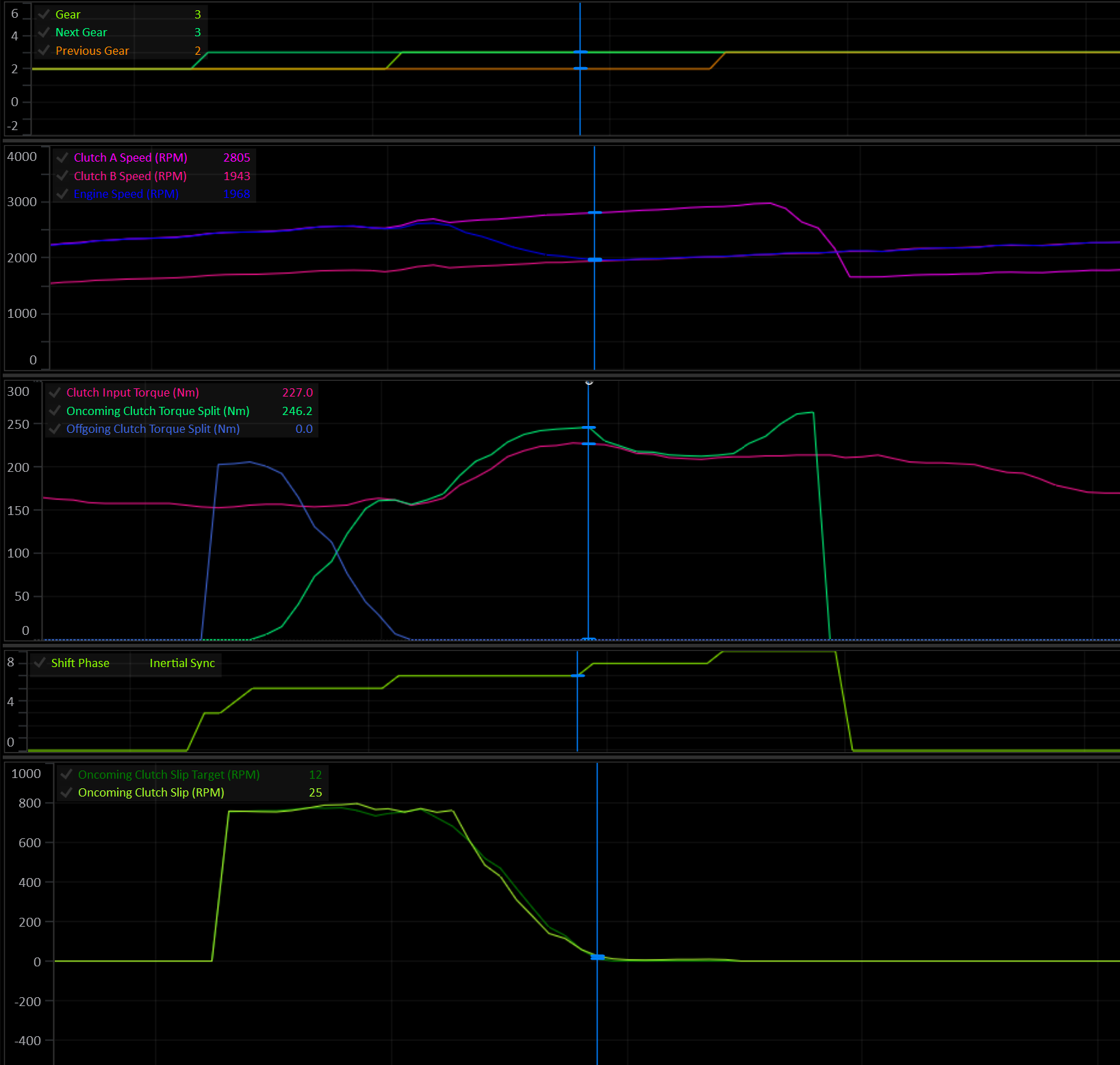
The Engine Speed is now matching Clutch B (oncoming) at the end of the Inertial Sync phase.
Torque Reductions
Any torque reduction that is enabled by the user is applied now to aid in syncing the Input Shaft Speed. Using torque reductions mean less clutch capacity is needed to achieve synchronization.
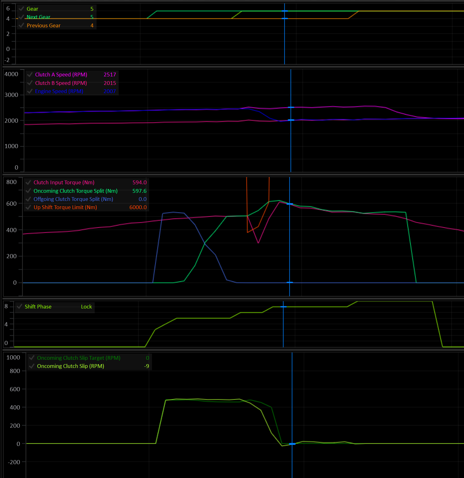
Up shift torque limit gets applied at the start of the Inertial Sync phase and is removed as slip approaches zero.
Tip
If the engine continues to limit torque after the clutch is synced and locked, the shift will feel harsh.
There are 3 tables that control the up shift torque limit:
- Up Shift Torque Limit Enable: determines if a torque limit is allowed or not.
- Up Shift Torque Limit: Absolute explicit torque limit value.
- Up Shift Torque Reduction: Torque reduction as a percentage of Engine Torque (Available).
The lowest torque limit output from the tables will be used.
For Example:
Because 480 Nm is less than the 500 Nm absolute limit, 480 Nm will be used.
Lock Phase
The Lock phase is used to eliminate any remaining clutch slip. A user definable amount of additional torque capacity is applied to the clutch during the lock phase.
Shift Tuning
The torque modelled approach to shifting dramatically reduces the tuning complexity of gear shifts for the end user, provided the input torque is accurate and the Clutch Configuration is accurate.
The goal when tuning a shift is simply to achieve the slip target throughout the shift. If the slip is on target then the only thing left to do is dial in the feel by manipulating the shift target times.
The runtimes to watch are Oncoming Clutch Slip Target and Oncoming Clutch Slip. Ideally they should lay over each other.
If a shift feels harsh, check the slip curve. If the slip is on target, extend the shift times before looking for a way to alter the clutch pressure or clutch torque capacity.
Tuning Considerations:
- The Clutches Geometry Model has the most influence over clutch torque calculations during a shift.
- The amount of torque to added to sync engine speed during the Inertial Sync Phase is determined by the Engine’s Inertia setting. Incorrect engine inertia will result in poor synchronization.
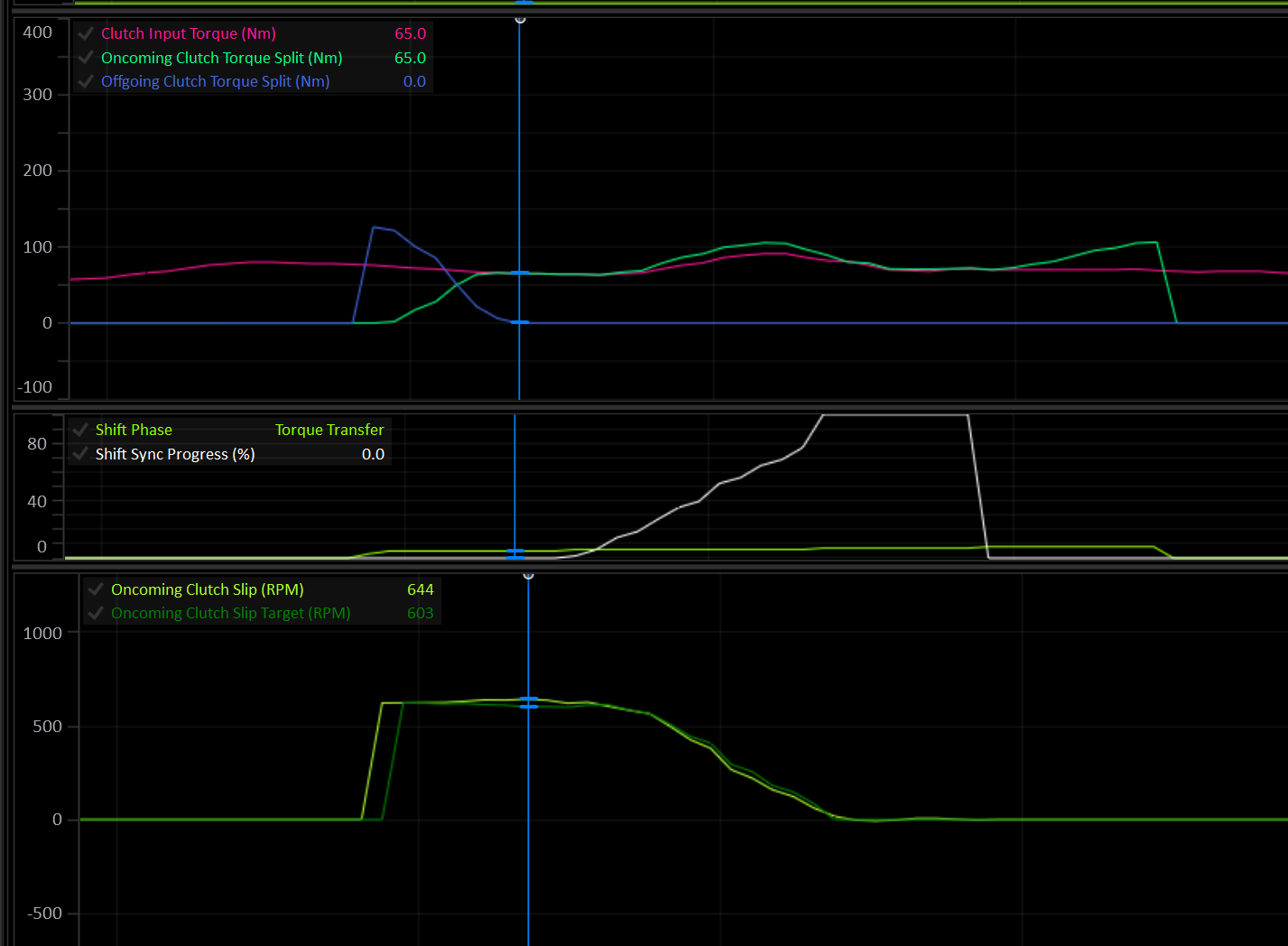
Ideal clutch slip curve during an upshift.
Shift Runtimes
When looking to see what’s happening during a shift there are several important runtime channels to watch:
- Shift Phase: Shows which phase the shift is currently in.
- Clutch Input Torque: This is the torque that all the clutch pressure calculations use as their input reference. Most of the time this is the same as
Engine Torque (Supplied). - Clutch # Input Torque: Each clutch may have a different input torque depending on it’s current Gear Load Factor Table value.
Clutch # Input Torque = Clutch Input Torque x Clutch # Gear Load Factor - Oncoming Clutch Torque Split: During a shift, this is the calculated torque that the oncoming clutch is required to hold. The value seen here is before any closed loop intervention. It’s the raw output of the shift modelling and inertia factors.
- Offgoing Clutch Torque Split: During a shift, this is the calculated torque that the offgoing clutch is required to hold. The value seen here is before any closed loop intervention. It’s the raw output of the shift modelling and inertia factors.
- Oncoming Clutch Slip Target: How much slip the oncoming clutch should have for an ideal shift, to meet the user’s shift time targets.
- Oncoming Clutch Slip: The actual slip of the oncoming clutch. During ideal shift conditions, this will usually lay over the top of the target value. It’s very possible and expected that under some conditions this will not be the case, for example: During a rev-matched downshift where the synchronization of the engine speed is not controlled by the TCM.
- Shift P Gain: Shift closed loop control proportional output.
- Shift I Gain: Shift closed loop control integral output.
- Shift D Gain: Shift closed loop control derivative output.
- Clutch # Torque Capacity: The actual calculated torque capacity of the clutch derived from it’s currently applied pressure. This value is after all closed loop control and rate limiting has been applied.
Touch Points
Important
It is critical that the Clutch Touch Points are setup at the outset. Poorly configured touch points will always lead to bad shifting and drivability.
For detailed information on setting touch points see here.
Clutch Capacity Learning
The Clutches Geometry Model and engine inertia value will control the majority of the clutch torque applied during a shift. During a shift, the closed loop PID algorithm will make adjustments to the final clutch torque to try and keep the slip curve on target. After a shift, as long as the conditions are met, the Clutch Capacity Adaption system will look at the previous shift’s closed loop output and make small adjustments to the relevant clutch’s Learned Capacity Scaler.
Shift Fork Control
This guide covers setup and calibration of the hydraulically actuated Shift Forks used to control gear selection in Dual Clutch Transmissions (DCT).
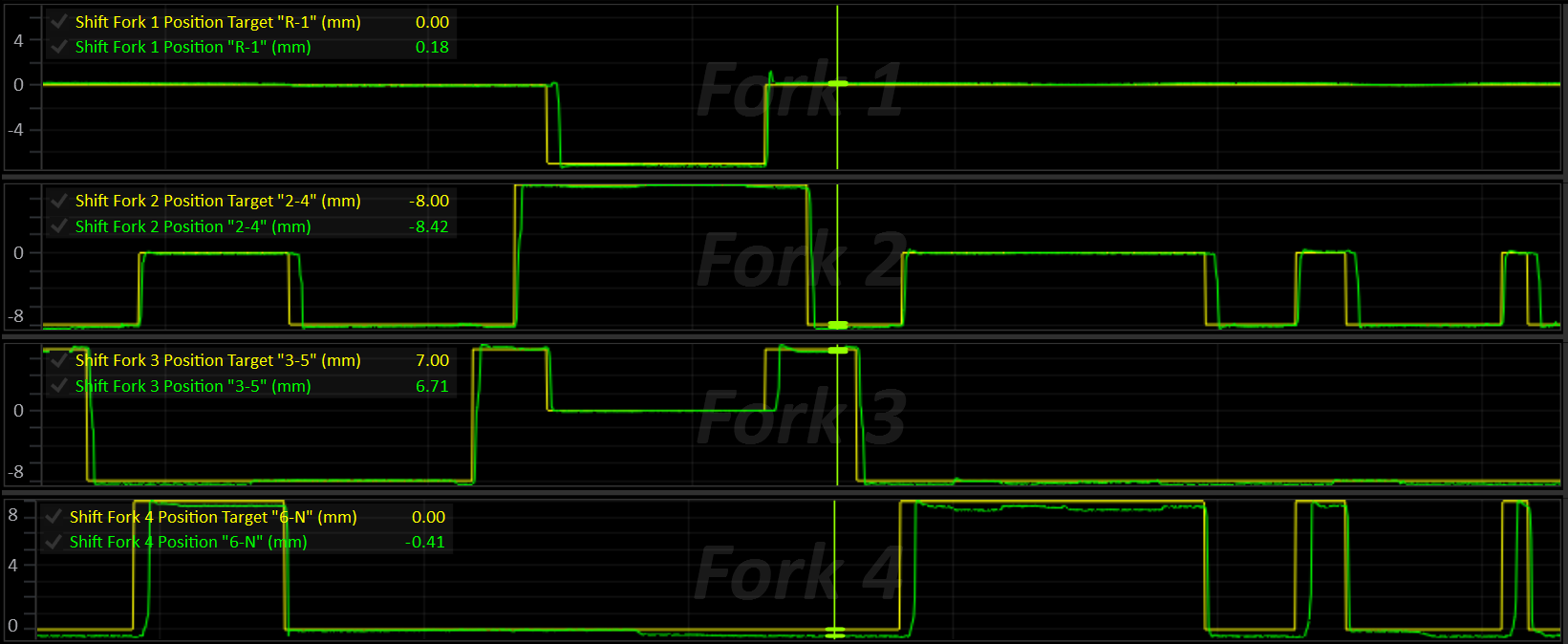
Concepts
Axes
A DCT has two input shafts (“axes”), each carrying its own clutch. While one axis is transmitting drive, the other is free to pre-select the next gear so that the shift itself is just a clutch hand-off, with no torque interruption. Every gear (including Reverse) belongs to one of these two axes:
| Clutch | Axis | Typical Gears |
|---|---|---|
| A | A | Even gears |
| B | B | Odd gears |
The active axis is whichever axis currently has a gear engaged and is transmitting drive.
The inactive axis is free to move its fork(s) to pre-select the next gear.
Clutch Axes
The TCM will always assume that the clutch and axis are a matched pair:
- Clutch A is on Axis A
- Clutch B is on Axis B
Shift Forks
A shift fork is a physical selector that can sit in one of three positions (“slots”):
| Slot | Meaning |
|---|---|
| Low | Engages the fork’s “Low” gear |
| Centre | Neutral (no gear engaged on that fork) |
| High | Engages the fork’s “High” gear |
Each fork belongs to one axis (or, for a shared Reverse fork, both axes) and is responsible for up to two gears, one on its Low side and one on its High side.
Up to 8 forks and 8 shift solenoids are supported.
While driving:
- The active axis must already have its current gear’s fork engaged (all other forks on that axis in Neutral).
- The inactive axis may have, at most, the pre-selected next gear’s fork engaged (all others in Neutral).
Only one fork is ever moved at a time. A fork on the active axis is never moved unless it’s explicitly required (e.g. a shift out of Neutral/Park), and a fork that needs to return to Neutral is always preferred over one that’s about to engage a new gear, so the way is cleared before a new gear goes in.
Fork Position Sensing
Each fork has a position sensor that is scaled and calibrated to report the fork’s measured position in millimeters. Some forks also have a secondary tracking sensor used purely for cross-checking / diagnostics.
Fork Position 1-8 inputs are configured in Input Setup.
The fork’s calibrated Low / Centre / High positions and tolerance bands are what translate this raw position into a slot (Low / Centre / High / Moving).
Fork Management
At all times the shift fork system is actively performing the following tasks:
- Each fork’s target is set:
- Active-axis forks target the current gear.
- Inactive-axis forks target the pre-selected gear.
- Everything else targets Neutral.
- Each fork’s own position/slot state is updated.
- Axis “binding” is detected if more than one fork on an axis reports being in gear at once.
- An axis fault is raised if any fork on that axis is in a position error state.
Fork Movement
- If a fork is currently moving, its movement is monitored until complete.
- Otherwise, the next fork that needs to move is found (inactive axis first, unless an active-axis move is explicitly allowed) and its movement begins.
- The physical shift solenoids are driven to move the current fork, or to hold the idle/default solenoid pattern when nothing is moving.
- If Axis Pressure Control solenoids are in use, their pressure is modulated to control fork movement speed.
- The moving fork is driven either toward its target position (default), or through a series of engagement phases when Engagement Phase Control is enabled.
Shift Procedure
- The currently engaged gear and its axis are marked as active.
- The Preselection system predicts the next shift direction (up or down) and selects the next gear on the inactive axis.
- On a shift request, the next gear’s fork is determined and pre-selected (if it’s not already) on the inactive axis.
- Once the pre-selected gear’s axis is ready (fork in target slot, no axis error), the clutch hand-off for the shift can proceed.
- After the shift completes, the new gear’s axis is marked as active, the offgoing axis is marked inactive.
- The Preselection system resumes prediction of the next shift on the newly inactive axis.
Configuration & Calibration
Shift Fork Setup (Global)
These apply to whichever fork is currently moving, regardless of which fork it is.
| Setting | Description |
|---|---|
| Shift Fork Stable Velocity (+/-) | Fork velocity threshold (± mm/s). Once a fork is inside its target slot’s tolerance band and below this velocity, its “stable” timer starts. Set to 0 to disable the velocity check (stability then depends only on being in-slot) |
| Shift Fork Stable Time | Time (ms) the fork must remain in-slot and stable before the move is considered complete |
| Engagement Phase Control | Selects how a moving fork is driven. OFF = the fork is driven toward its target position. ON = the fork is driven through a series of engagement phases, see Engagement Phase Control |
| Fork Move Idle Target | Idle speed requested from the ECU while a gear is engaged from Neutral or Park at a standstill. Engagement Phase Control only, see Standstill Engagement Aids |
Shift Fork Setup (Per-Fork)
Each fork (numbered 1–8) is independent and must be configured individually. Below, “#” stands for the fork number, eg: “Shift Fork 3 Axis”.
| Setting | Description |
|---|---|
| Shift Fork # Axis | Parent axis: Disabled / Axis A / Axis B / Both (shared, e.g. Reverse) |
| Shift Fork # Label | Free-text label for the fork (shown in the tuning software UI) |
| Shift Fork # Position L Gear | Gear engaged when the fork is in its Low slot. OFF = slot unused. |
| Shift Fork # Position H Gear | Gear engaged when the fork is in its High slot. OFF = slot unused. |
| Shift Fork # Position L | Target fork position for the Low slot (mm) |
| Shift Fork # Centre | Target fork position for the Centre (Neutral) slot (mm) |
| Shift Fork # Position H | Target fork position for the High slot (mm) |
| Shift Fork # Position L Tolerance (+/-) | Position tolerance (± band) around the Low slot (mm) |
| Shift Fork # Centre Tolerance (+/-) | Position tolerance (± band) around the Centre slot (mm) |
| Shift Fork # Position H Tolerance (+/-) | Position tolerance (± band) around the High slot (mm) |
| Shift Fork # Error Detection | Enables position error detection; bit 1 auto-clears the error once the fork returns to its target slot |
| Shift Fork # Error Auto Clear | Auto-clears the error once the fork returns to its target slot |
| Shift Fork # Error Delay | Time the fork may be out of its target slot before a position fault is raised (0–25.0 s) |
| Shift Fork # Retry Limit | Number of retries allowed after the first attempt before the fork raises a position fault. 0 = a single attempt only. See Per-Fork Position Error and Stalls and Retries |
| Shift Fork # Test | Bench/service test override: Off / Force Low, / Force Centre, / Force High. Only takes effect while the requested gear is Neutral or Park |
Notes:
- The Low and High slot positions do not need to be numerically low/high — the firmware automatically detects whether the fork’s travel is inverted (i.e. the Low position is a larger number than Centre) and corrects the shift-direction logic accordingly.
- Whichever gear ends up on the Low slot vs. High slot is purely a function of fork travel direction — set the Low/High gear assignments to match the physical gear each end of travel actually engages.
- A fork does not need both slots populated — a single-sided fork (e.g. Reverse-only) should leave the unused Low/High gear assignment at
0.
Shift Solenoid Selection
Which solenoids are energised to move a fork in a direction is controlled by the solenoid select tables.
| Table | Description |
|---|---|
| Shift Fork # Positive Solenoid Select | Selects which shift solenoid(s) (1–8) are energised to move the fork in the positive position direction (+ mm) |
| Shift Fork # Negative Solenoid Select | Selects which shift solenoid(s) (1–8) are energised to to move the fork in the negative position direction (- mm) |
| Shift Fork Idle Solenoid Select | Shift solenoid(s) held on when no fork is currently moving (idle hold pattern) |
| Default Shift Solenoid Select | Shift solenoid(s) always added to the active pattern in addition to the moving/idle pattern, when the default overlay is enabled |
| Default Shift Solenoid Enable | Enables/disables the default solenoid overlay above (non-zero = enabled) |
Important
The solenoid select table’s X-axes must be Shift Solenoid #. Multiple solenoids can be selected at once.
Per-Fork Position Sensor Calibration
Shift Fork n Position is reported in mm.
Each fork has a position sensor that can be calibrated in Input Config > Transmission Inputs > Shift Fork Positions.
It is critical that these position sensor inputs are assigned and calibrated correctly.
Fork Movement Pressure Control
While a fork is moving, its physical movement can optionally be driven by a
closed-loop position PID acting on hydraulic pressure (rather than a fixed pressure). The need for pressure control will depend on the transmission design.
When enabled, the Axis Pressure solenoids are controlled to achieve the desired pressure.
With Engagement Phase Control ON, the PID is not used. The pressure is instead set by the force of the current engagement phase, as a percentage of the maximum fork movement pressure (see Engagement Phase Control).
| Setting / Table | Description |
|---|---|
| Axis Pressure Override | Enables the axis pressure override: while set, the axis pressure of whichever axis is physically moving is driven by the fork-movement PID (or by Engagement Phase Control) instead of the normal active/inactive axis pressure targets |
| Fork Movement Pressure Base | Base (feed-forward) pressure added ahead of the PID output (Bar). Engagement Phase Control OFF only |
| Fork Movement Pressure Proportional Gain | PID proportional gain for fork movement pressure control. Engagement Phase Control OFF only |
| Fork Movement Pressure Integral Gain | PID integral gain for fork movement pressure control. Engagement Phase Control OFF only |
| Fork Movement Pressure Derivative Gain | PID derivative gain for fork movement pressure control. Engagement Phase Control OFF only |
| Axis Pressure Override Integral Min / Max | PID integral clamp (Bar). Engagement Phase Control OFF only |
| Axis Pressure Override Min / Max | Output pressure clamp (final PID output is constrained to this range) (Bar) |
| Fork Movement Pressure Max | Maximum fork movement pressure (Bar). The lower of this table and Axis Pressure Override Max is used. 0 = use Axis Pressure Override Max. With Engagement Phase Control ON, this is the pressure that equals 100% fork force |
Fork Movement Current Control
Transmissions that set fork force through the shift solenoid current rather than axis pressure (e.g. Getrag GS7) use Variable Force shift solenoids. While a solenoid is energised, its current is taken from its Shift Solenoid # Current table. The table’s axis can be chosen to suit the fork movement mode:
| Table Axis | Behaviour |
|---|---|
Active Shift Fork Position Error | High current far from the target slot, tapering as the fork arrives. Suits position control (Engagement Phase Control OFF). |
Shift Fork Force Demand | Current follows the force requested for the fork (0 - 100%), so the table becomes a force-to-current map. Required for Engagement Phase Control. |
Leave Axis Pressure Override OFF on these transmissions.
Torque Limiting During Fork Movement
Active Axis Fork Movement Torque Limit can be applied applied while a fork on the currently active axis is moving (e.g. Shifts out of Neutral/Park, where the axis being engaged is also the “active” axis).
Engagement Phase Control
Engagement Phase Control is an alternative way of driving a moving fork, built around how a synchroniser engages a gear. Instead of simply pushing the fork toward its target position, the TCM steps the fork through a series of phases (approach, synchronise, engage and settle), each with its own force. If the fork stalls, it’s backed off, rested and tried again with a little more force, rather than being held hard against the synchroniser.
This makes the biggest difference when engaging a gear from Neutral or Park at a standstill, where drag from the open clutch keeps the shaft spinning. A fork that is just pushed harder tends to sit on the synchroniser, using it as a brake against the clutch drag. Engagement Phase Control detects this, backs off and retries, and limits how hard and how long the synchroniser is worked.
It works with both pressure-actuated forks (e.g. Nissan GR6) and forks whose force is set by the shift solenoid current (e.g. Getrag GS7).
Enabling Engagement Phase Control
Set Engagement Phase Control to ON in Shift Fork Setup. The Shift Fork Engagement Phase Control folder will then appear, containing the settings and tables described below.
All fork forces are set as a percentage (0 - 100%) of the fork’s maximum force. How that percentage is turned into an output depends on how the forks are actuated:
| Fork Actuation | Setup |
|---|---|
| Axis Pressure (e.g. Nissan GR6) | Set Axis Pressure Override to ON. 100% force is the lower of Fork Movement Pressure Max and Axis Pressure Override Max. Axis Pressure Override Min sets the minimum pressure while a fork is moving. The fork movement PID tables are not used. |
| Shift Solenoid Current (e.g. Getrag GS7) | Leave Axis Pressure Override OFF. Set the Solenoid Type of the shift solenoids that move the forks to Variable Force, and set the axis of each of their Shift Solenoid # Current tables to Shift Fork Force Demand. The table then converts the requested force (%) into solenoid current. |
Axis Pressure Example
- Fork Movement Pressure Max = 18.0 Bar
- Current phase force = 40%
- Fork movement pressure = 40% of 18.0 Bar = 7.2 Bar
Fork Travel and Sync Slip
Two channels are central to how Engagement Phase Control works, and to tuning it:
Shift Fork Travelis the moving fork’s progress, from 0% at the slot it’s leaving to 100% at its target slot. Where the synchroniser sits within that travel is set by Sync Zone Start and Sync Zone End. The sync zone is shared by all forks in both directions, so it must cover every fork’s synchroniser.Shift Fork Sync Slipis the speed difference the synchroniser has to remove before the gear can engage: the speed of the target axis clutch compared to the speed the target gear would turn it at. The shaft is considered synchronised once this falls below Synchro Slip Complete Threshold. Correct clutch speed and output shaft speed readings are required.
Move Phases
Each fork move steps through the following phases, reported by Shift Fork Move Phase:
| Phase | Description |
|---|---|
| Idle | No fork is moving. |
| Approach | The fork leaves its slot at Shift Fork Approach Force and travels toward the synchroniser, until it reaches Sync Zone Start. |
| Sync | The synchroniser is loaded. Force starts at Shift Fork Sync Force Start and rises at Sync Force Ramp Rate up to the force ceiling for this attempt (Sync Force Max on the first attempt). Sync ends once the blocker ring releases and the fork passes Sync Zone End. |
| Engage | The blocker ring has released and the fork rides the dog teeth into the slot. Once the shaft is synchronised, the force changes to Shift Fork Engage Force. Until then, the force the ring released at is held, as the ring lets go slightly before the shaft is fully synchronised. If the fork is pushed back onto the ring, it returns to Sync. |
| Settle | The fork has reached its target slot and the shift solenoids are off. The move is complete once the fork has been stable in the slot for Shift Fork Stable Time (see Shift Fork Stable Velocity). If the fork bounces out of the slot, the solenoids stay off until it has come to rest, so a fork overshooting Neutral isn’t pushed back and forth between the two directions. If it comes to rest outside the slot, it’s driven back in. |
| Back Off | After a stall, the fork is pulled back toward the slot it came from by Back-Off Distance at Back-Off Force, for no longer than Back-Off Time. The fork is never pulled back past the slot it came from. |
| Rest | The shift solenoids are turned off for Retry Rest Time, allowing the synchroniser to re-centre before the next attempt. |
| Error | All attempts have been used. The fork enters its position error state, see Per-Fork Position Error. |
A fork returning to Neutral has no synchroniser to work against, so it goes straight from Approach to Engage.
Stalls and Retries
When a fork stops making progress toward its target, the TCM records why in Shift Fork Stall Type, backs the fork off, rests, then tries again.
| Stall Type | Phase | Cause |
|---|---|---|
| None | - | No stall has occurred during this move. |
| Mechanical | Approach | The fork stopped making progress for Approach Stall Time, or didn’t reach Sync Zone Start within Approach Timeout. The stall timer only starts once the fork has begun to move. |
| Blocker Ring | Sync | The blocker ring didn’t release within Sync Timeout. Or, the shaft was synchronised but the fork didn’t move for Synchro Settled Timeout with the force at its ceiling (clutch drag is holding the ring in place). |
| Equilibrium | Sync | With the force at its ceiling, Shift Fork Sync Slip didn’t fall by at least Synchro Slip Progress Validation within each Synchro Slip Progress Window. The synchroniser can’t overcome the clutch drag, so the attempt is abandoned early rather than using the synchroniser as a brake for the full Sync Timeout. |
| Dog Teeth | Engage | The fork sat, or bounced, on the dog teeth without making progress for Dog Engagement Stall Time. |
Retries work as follows:
- Each retry raises the Sync force ceiling by Sync Retry Force Step (up to 100%). The first attempt can be gentle, with force only increasing when the synchroniser needs it.
- Each fork is allowed its Shift Fork # Retry Limit retries after the first attempt. Once they have all failed, the fork enters its position error state.
- The fork’s Error Delay still limits the total time of the whole move, including every attempt.
- After a synchroniser stall (Blocker Ring or Equilibrium), the rest ends early as soon as the shaft is synchronised.
- After a Dog Teeth stall, the rest ends early as soon as the shaft has turned relative to the gear, giving the teeth a new position to engage.
Shift Fork Crash Count counts (per fork, since power up) engagements where the dog teeth went in while the shaft was still slipping above Synchro Slip Complete Threshold, i.e. the gear was forced through the synchroniser. A rising count means the Sync force ceiling is too high, or there is too much drag on the target axis.
Synchroniser Heat Protection
Repeated attempts heat the synchroniser. Shift Fork Sync Energy estimates this for each fork by accumulating slip x force x time while the synchroniser is loaded, and decays over roughly 20 seconds.
While Shift Fork Sync Energy is above Sync Energy Limit, the rest between attempts is extended from Retry Rest Time to Sync Energy Limit Cooldown. Set Sync Energy Limit to 0 to disable.
Standstill Engagement Aids
Two optional functions help engage a gear from Neutral or Park while the vehicle is stationary.
Dog Engagement Stall Clutch Pulse
If the fork stalls on the dog teeth with the shaft already synchronised, the teeth are likely sitting tip to tip. When enabled, the target axis clutch is briefly applied during the rest, at its touch point + Dog Engagement Stall Clutch Pulse Pressure for Dog Engagement Stall Clutch Pulse Time. This turns the shaft a few degrees so the teeth can line up on the next attempt.
- Only the clutch on the axis being engaged is pulsed, and only while nothing is engaged on that axis.
- It’s never used after a synchroniser stall.
Shift Fork Clutch Pulse Statusis ON while the pulse is applied, and the clutch status reportsOn - Shift Fork Clutch Pulse.
Fork Move Idle Target (Shift Fork Setup)
A lower engine idle speed means less clutch drag for the synchroniser to overcome. While a gear is being engaged from Neutral or Park at a standstill, the Fork Move Idle Target is output on Shift Fork Idle Speed Request (0 at all other times). To use it, transmit Shift Fork Idle Speed Request to the ECU in a CAN message and configure the ECU to use it as its idle target. Set to 0 to disable.
Engagement Phase Settings
Found in Shift Fork Engagement Phase Control > Shift Fork Engagement Phase Setup.
| Setting | Description |
|---|---|
| Approach Stall Time | Time the fork may go without making progress during Approach before a Mechanical stall is declared. The timer only starts once the fork has begun to move, so it doesn’t need to allow for break-away (ms) |
| Approach Timeout | Approach must reach Sync Zone Start within this time, or a Mechanical stall is declared (ms) |
| Sync Zone Start | Fork travel at which the fork reaches the blocker ring and the Sync phase begins (0% = slot being left, 100% = target slot). Set comfortably below the travel where forks are seen to stall on the synchroniser (%) |
| Sync Zone End | Fork travel at which the blocker ring is considered released and the Engage phase begins. Set above the highest synchroniser stall position, and below where the dog teeth are reached (%) |
| Sync Timeout | Longest time the synchroniser is loaded in one attempt before the fork backs off. Limits synchroniser heating (ms) |
| Sync Force Ramp Rate | Rate the force rises from Shift Fork Sync Force Start up to the force ceiling. A slow ramp spends longer at a force where the synchroniser can work. A fast ramp reaches the ceiling quickly and is more likely to push through the blocker ring before the shaft is synchronised (%/s) |
| Sync Force Max | Force ceiling for the first attempt. Should be below the force that pushes the fork through the blocker ring while the shaft is still spinning (%) |
| Sync Retry Force Step | Added to the force ceiling on each retry, up to 100% (%) |
| Synchro Slip Progress Validation | With the force at its ceiling, Shift Fork Sync Slip must fall by at least this much every Synchro Slip Progress Window, or an Equilibrium stall is declared (RPM) |
| Synchro Slip Progress Window | Time window over which slip progress is checked (ms) |
| Synchro Slip Complete Threshold | Shift Fork Sync Slip below which the shaft is considered synchronised (RPM) |
| Synchro Settled Timeout | If the shaft is synchronised with the force at its ceiling, but the fork isn’t moving for this long, a Blocker Ring stall is declared so the ring can re-centre (ms) |
| Sync Energy Limit | Synchroniser heat limit, compared with Shift Fork Sync Energy. 0 = disabled |
| Sync Energy Limit Cooldown | Rest time used instead of Retry Rest Time while the synchroniser is over its Sync Energy Limit (ms) |
| Dog Engagement Stall Time | Time the fork may go without making progress on the dog teeth during Engage before it backs off (ms) |
| Back-Off Distance | How far the fork is pulled back toward the slot it came from after a stall. Enough to fully unload the blocker ring or clear the dog teeth (mm) |
| Back-Off Time | Longest time the back off is driven if Back-Off Distance isn’t reached (ms) |
| Back-Off Force | Force used to pull the fork back after a stall. It only needs to unload the ring or lift the fork off the dog teeth, not move quickly (%) |
| Retry Rest Time | Time the shift solenoids are off between attempts (ms) |
| Dog Engagement Stall Clutch Pulse | Enables the dog stall clutch pulse, see Standstill Engagement Aids |
| Dog Engagement Stall Clutch Pulse Pressure | Pressure above the clutch touch point applied during the pulse. Just enough to turn an unloaded shaft (Bar) |
| Dog Engagement Stall Clutch Pulse Time | Length of the pulse. The rest between attempts is held until the pulse has finished (ms) |
Force Tables:
| Table | Description |
|---|---|
| Shift Fork Approach Force | Force from leaving the slot until the fork reaches Sync Zone Start. Enough to move the fork briskly, without throwing it at the blocker ring. Too low and the fork won’t break away, resulting in a Mechanical stall (%) |
| Shift Fork Sync Force Start | Force when the fork first loads the blocker ring. The synchroniser works best at a moderate force, so starting low gives it a chance to synchronise the shaft before the force ramps up. Consider spanning this table against Output Shaft Speed, so pre-selection while driving starts closer to the ceiling and only standstill engagements start gently (%) |
| Shift Fork Engage Force | Force used to push the fork through the dog teeth into the slot once the shaft is synchronised. Too low and the fork will stall on the dog teeth. Too high and it will slam into the slot (%) |
Tuning Engagement Phase Control
Complete the standard Calibration Procedure first. Fork travel is measured between the calibrated slot positions, so these must be accurate.
Check
Shift Fork Sync Slipreads sensibly during a fork movement. It relies on correct clutch speed and output shaft speed readings.Set up the force range for the fork actuation type, see Enabling Engagement Phase Control.
Enable Engagement Phase Control and log a number of engagements from Neutral at a standstill, as well as pre-selections while driving. Log
Shift Fork Move Phase,Shift Fork Stall Type,Shift Fork Move Attempt,Shift Fork Travel,Shift Fork Sync Slip,Shift Fork Force DemandandShift Fork Crash Count, along with each fork’s Position.Set the sync zone from
Shift Fork Travelat the point where each fork stalls on the synchroniser. Sync Zone Start should be below the lowest stall point, and Sync Zone End above the highest.Set Shift Fork Sync Force Start low enough that the synchroniser has a chance to work before the force ramps up to its ceiling. Only then raise Sync Force Max if forks still fail to engage.
Watch
Shift Fork Crash Count. A rising count means the force ceiling is overpowering the blocker ring rather than letting the synchroniser work. The fix is less force or less drag (e.g. a lower idle with Fork Move Idle Target), not more force.Review stall types at a standstill. Repeated Equilibrium stalls mean clutch drag is too high for the synchroniser to overcome, so reduce drag rather than adding force. Repeated Dog Teeth stalls with the shaft synchronised can be helped by the Dog Engagement Stall Clutch Pulse.
Set each fork’s Retry Limit and Error Delay last, once engagement is reliable.
Errors & Diagnostics
Per-Fork Position Error
If a fork’s error-detection is enabled, a fork that fails to reach its target slot within its Error Delay (or whose position sensor reports a fault) raises a Fork # Movement fault and enters an internal error state.
From the error state, the firmware automatically retries the move, up to the fork’s Retry Limit, 1 second apart. With Engagement Phase Control ON, retries are made within the move itself (see Stalls and Retries), so there are no further automatic retries once the fork has entered the error state. If Error Auto Clear is enabled, the error clears automatically once the fork successfully reaches its target slot again (and the position sensor is healthy) — this is normally only allowed to happen when the fork’s target is Centre (Neutral), so a fork always has to prove it can get back to a safe state before being trusted again.
Using the tuning software’s “Clear All Codes” action also resets every fork’s retry count, in addition to clearing the fault codes themselves — so a fork that had exhausted its retries gets a fresh set of attempts on its next movement, rather than immediately re-latching into a fault.
Axis errors
Each axis is also monitored as a whole:
| Fault | Cause |
|---|---|
| Axis A Bound / Axis B Bound | More than one fork on that axis reports being in gear simultaneously — i.e. the axis is mechanically bound between two gears |
| Axis A Fault / Axis B Fault | At least one fork on that axis is in a position error state |
While an axis is in fault, no fork on that axis will be moved until the fault clears.
Related channels for diagnosis
See Runtime Channels for the full list. Each fork’s Status and Position Error, and the Moving Shift Fork channel, are usually the first things worth logging when diagnosing a shift fork issue.
Runtime Channels
Per-Fork Channels (# = fork number, 1–8):
| Channel | Description |
|---|---|
| Shift Fork # Position | Measured fork position, mm |
| Shift Fork # Position Target | Target fork position, mm |
| Shift Fork # Position Error | Position error (target − measured), mm |
| Shift Fork # Velocity | Measured fork velocity, mm/s |
| Shift Fork # Status | see Shift Fork Status enumeration |
| Shift Fork # Tracking | Secondary/tracking position sensor reading (diagnostic only) |
System-Wide Channels:
| Channel | Description |
|---|---|
| Selected Gear A | Gear currently engaged on Axis A |
| Selected Gear B | Gear currently engaged on Axis B |
| Active Gear Shift Fork | Fork responsible for the currently active (engaged) gear |
| Preselected Gear Shift Fork | Fork responsible for the pre-selected next gear |
| Moving Shift Fork | Fork currently moving |
| Active Shift Fork Position | Position of whichever fork is currently moving |
| Active Shift Fork Position Target | Target position of whichever fork is currently moving |
| Active Shift Fork Position Error | Position error of whichever fork is currently moving |
| Active Axis Pressure Target | Active axis clutch pressure target, Bar |
| Inactive Axis Pressure Target | Inactive axis clutch pressure target, Bar |
| Active Axis Fork Movement Torque Limit | Torque limit currently applied due to active-axis fork movement |
| Shift Fork Movement Pressure | Fork movement pressure demand output, Bar |
| Shift Fork Movement Pressure Base | Fork movement pressure base/feed-forward term |
| Shift Fork Movement Pressure P Gain | Fork movement pressure PID proportional term |
| Shift Fork Movement Pressure I Gain | Fork movement pressure PID integral term |
| Shift Fork Movement Pressure D Gain | Fork movement pressure PID derivative term |
| Shift Fork Force Demand | Force requested for the moving fork, % of maximum. Also reported with Engagement Phase Control OFF while Axis Pressure Override is ON |
Engagement Phase Control Channels:
| Channel | Description |
|---|---|
| Shift Fork Move Phase | Phase of the moving fork, see Shift Fork Move Phase enumeration |
| Shift Fork Stall Type | Reason for the most recent back off, see Shift Fork Stall Type enumeration and Stalls and Retries |
| Shift Fork Move Attempt | Attempt number of the current move, 1 = first attempt. 0 when no fork is moving |
| Shift Fork Phase Time | Time spent in the current phase, ms |
| Shift Fork Travel | Fork progress from the slot it’s leaving (0%) to its target slot (100%) |
| Shift Fork Sync Slip | Speed difference the synchroniser has to remove, RPM. 0 for a return to Neutral |
| Shift Fork Crash Count | Number of engagements of the moving fork, since power up, where the dog teeth went in with the shaft still slipping |
| Shift Fork Sync Energy | Heat estimate for the moving fork’s synchroniser, compared with Sync Energy Limit |
| Shift Fork Clutch Pulse Status | ON while the Dog Engagement Stall Clutch Pulse is applied |
| Shift Fork Idle Speed Request | Idle speed requested from the ECU during a standstill engagement, RPM. 0 when not requested |
Calibration Procedure
Enable each fork — set the Axis setting for every physical fork fitted (Axis A, B, or Both for a shared Reverse fork). Leave unused fork slots OFF.
Wire up and calibrate position sensors first, via the standard analog input mapping/translation tools, so that each fork’s Position channel reads a correctly-scaled value (mm) across the whole range of travel.
Set tolerance bands (Low/Centre/High Tolerance) tight enough to confirm the dog teeth/synchro are actually engaged, but loose enough to tolerate normal sensor noise and mechanical play.
Assign gears to each slot via Position L Gear / Position H Gear. You may have to put some educated guesses into the positions initially.
Assign shift solenoids per fork (Positive/Negative Solenoid Select) and confirm direction — command a move with Test mode and verify the fork moves the correct way and its Status reports moving in the expected direction, then settles into the correct slot.
Set idle/default solenoid patterns (Idle Solenoid Select, Default Select / Enable) as required by the actuator hardware.
Find and record the three slot positions for each fork with the vehicle safely supported and the driveline free to move by hand, or using the fork’s Test setting to command it to each slot in turn (only works while the requested gear is Neutral or Park):
- Force to Low, record the settled Position reading into Position L.
- Force to Centre, record Centre position.
- Force to High, record Position H.
- Set Test back to Off when done.
Tune move-complete detection — Stable Velocity and Stable Time — so a fork isn’t reported as “done” while still settling, but without adding unnecessary delay to every shift.
Tune fork movement pressure (if using closed-loop pressure control): set the Movement Pressure Base and PID gains, and the Pressure Override Min/Max and Integral Min/Max clamps, then set Axis Pressure Override to ON if pressure-based fork actuation is desired instead of fixed axis pressure targets. If using Engagement Phase Control, follow Tuning Engagement Phase Control instead.
Set error detection last, once movement is proven reliable. Set each fork’s Error detect / Auto-Clear and Error Delay, generous enough to allow for normal shift timing but tight enough to catch a stuck fork.
Verify full shift sequences in all gears, both directions, watching the Active Gear Shift Fork, Preselected Gear Shift Fork and Moving Shift Fork channels. Watch each fork’s Status & Position, for consistent, movement and engagement. Confirm no Axis Bound/Axis Fault faults occur across the full gear range.
Takeup
Takeup manages the smooth application (and release) of clutch torque from a standing start. The equivalent of a driver gently feeding out a manual clutch pedal, done automatically. It’s a critical function for dual-clutch transmissions, and an optional feature on multi-clutch transmissions that are also equipped with a torque converter.
Takeup doesn’t select gears or bring in extra clutches on its own — it only takes over the pressure of whichever clutch is already engaged for the current gear, for as long as the car is moving off from (or slowing to) a stop.
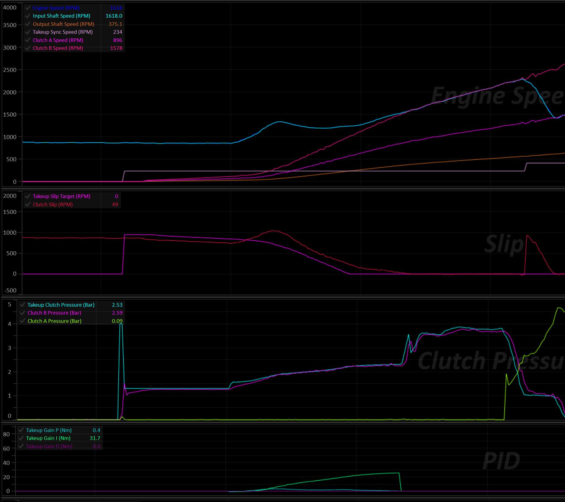
Enabling and Selecting the Clutch
Set Enable to turn Takeup on. Once enabled, the Takeup Clutch Select table determines which clutch Takeup is allowed to take control of, per gear. This only has effect for a clutch that’s already part of the active clutch set for the current gear; it cannot bring in a clutch on its own. Configure one clutch per gear for a standard standing-start setup.
Takeup Clutch Select Table
- X Axis: MUST be
Clutch #. - Y Axis: MUST be
Gear.
Select a clutch for each gear, even if it’s not intended for normal operation.
If a clutch is not selected for the current gear, the Takeup system will not arm in that gear. In the event of a failure where the transmission is forced to stay in a unintended gear, this may result in the car being undriveable.
Speed Target Mode
Speed Target Mode sets what the closed-loop slip controller is trying to synchronize to.
| Mode | Behaviour |
|---|---|
| Off | Takeup Target Mode is 0 — Takeup is disabled regardless of the Enable setting. |
| Engine Speed | The Takeup Engine Speed Target table gives a target Engine Speed. The controller works out the clutch slip and synchronous Output Shaft Speed needed to bring the engine to that RPM in the current gear. |
| Input Shaft Speed | The Takeup Input Shaft Speed Target table gives a target Input Shaft Speed directly, again converted to a slip target and synchronous Output Shaft Speed for the current gear. |
| Clutch Slip | The Takeup Slip Target table is used directly as a raw the clutch slip target. No speed synchronization is calculated. |
In all three modes, as the car accelerates and Output Shaft Speed approaches the calculated Takeup Sync Speed, the required slip target tapers down toward zero — this is what lets the clutch lock up smoothly instead of stepping straight from “slipping” to “locked”.
Takeup States
Takeup is a 5-state machine:
| State | Meaning |
|---|---|
| Off | Function disabled, or just enabled while already moving faster than the Arming Output Shaft Speed. |
| Ready | Car stopped/slow. Clutch is held at a small Initial Clutch Torque (optionally preceded by a Fast Fill pulse). Waiting for the driver to get on the throttle. |
| Active | The car is actually launching. A closed-loop controller slips the clutch through to lock-up, tracking the Speed Target Mode’s target. |
| Exit | Takeup Sync Speed and Takeup Slip Target have been met. Pressure ramps the rest of the way up to full lock-up at a dedicated rate. |
| Driving | Fully locked, normal driving. Takeup is watching Output Shaft Speed in the background in case the car slows back down to a stop. |
Ready → Active
The transition from Ready to Active happens once all of the following are true:
- Brake Switch is off
- Pedal/Throttle is above Pedal/Throttle Min
- Engine Torque (Supplied) is above Engine Torque Min.
The system transitions back to Ready if any of the same three conditions reverse (with a small amount of built-in hysteresis so it doesn’t chatter back and forth right at the threshold).
Ready → Exit
If the car picks up speed past Takeup Sync Speed while still in Ready, before the driver has touched the pedal (e.g. rolling away on a hill, or creeping forward under a positive Initial Clutch Torque), Takeup skips Active and goes straight to Exit. The clutch is ramped up to full lock at the Takeup Exit Pressure Ramp Rate rather than sitting at Initial Clutch Torque while the car outruns it. This doesn’t happen while Bleed Off is active.
Active → Exit
Once Output Shaft Speed has risen above the calculated Takeup Sync Speed and Clutch Slip has fallen below the Exit Slip Threshold, the system hands off to the Exit state. The clutch pressure is ramped the rest of the way to full pressure at the Takeup Exit Pressure Ramp Rate.
If Output Shaft Speed falls back below Takeup Sync Speed (minus Output Shaft Speed Sync Hysteresis) before the ramp finishes, it returns to Active rather than continuing to lock up.
Exit → Driving
Once the ramped pressure has caught up to the normal fully-locked clutch pressure, Takeup hands off to the Driving state and stops actively managing that clutch’s pressure.
Driving → Active (coming back down to a stop)
Takeup continuously compares Output Shaft Speed against a re-arming point: Takeup Sync Speed (minus Output Shaft Speed Sync Hysteresis), optionally adjusted earlier by Decel Arming Lead Time during a fast deceleration so the release has a head start rather than only reacting once the car has nearly stopped.
If Arming Output Shaft Speed is set above 0, Output Shaft Speed must also drop below that fixed speed before Takeup re-arms. Set it to 0 to rely on the synchronous-speed comparison alone.
Caution
Pay attention to the table axis setup of the selected slip target table. The Takeup Sync Speed will likely move around if the table is spanned against channels such as Pedal Position. This can result in unintended Takeup re-arming. The Arming Output Shaft Speed setting is useful for eliminating this concern.
Stall-Saver: If Output Shaft Speed drops to the point that Input Shaft Speed would fall below the transmission’s configured Input Shaft Speed Min, Takeup re-arms immediately regardless of the above.
The same re-arming point also gates the way back out. Active (and Ready, when the car rolls past sync on its own) won’t hand off to Exit until Output Shaft Speed is above the re-arming point plus Output Shaft Speed Sync Hysteresis (or above Takeup Sync Speed, whichever is higher). This stops a fast coast-down from bouncing between Exit and Active, which would otherwise show up as a saw-tooth on the clutch pressure.
Lockouts
Takeup is held out of operation — clutch pressure and state are frozen — whenever any of the following are true:
| Lockout | Condition | Cooldown |
|---|---|---|
| Engine stopped | Engine Speed = 0 RPM | — |
| Neutral / Park | Selected Gear = Neutral or Park | — |
| User Lockout | The assigned User Function is OFF (only checked if one is assigned) | — |
| Clutch By Wire | Clutch By Wire Scaler is below Clutch By Wire Lockout (set the lockout to 100% to disable this check entirely) | Clutch By Wire Lockout Cooldown Time |
| Transbrake | Enabled via Transbrake Lockout; trips while the Transbrake is on or in its bump cooldown | Transbrake Lockout Cooldown Time |
| Launch Control | Enabled via Launch Control Lockout; trips while Launch Control is active | Launch Control Lockout Cooldown Time |
The Clutch-By-Wire, Transbrake, and Launch Control lockouts each have their own cooldown timer. Once the underlying condition clears, Takeup stays locked out for the configured cooldown period before it’s allowed to resume, rather than snapping back on the instant the condition goes away. When Takeup comes back out of one of these three lockouts, it re-evaluates whether the car is already moving fast enough to go straight to Driving, or whether it should resume in Ready.
Tip
If Takeup is enabled alongside Launch Control’s clutch override, it’s strongly recommended to enable the Launch Control Lockout so the two systems don’t fight over the same clutch.
Bleed Off
When enabled, Bleed Off removes all pressure from the takeup clutch, so it’s ready to fill from empty. It can be triggered by the Brake Switch (Bleed Off with Brake Switch) and/or the Takeup Bleed Off Enable table.
Two optional lockouts prevent Bleed Off from kicking in:
- Bleed Off Pedal/Throttle Max
- Bleed Off Output Shaft Speed Max
Above either one, Bleed Off is locked out even if the brake/table would otherwise call for it. Setting one of these lockouts to 0 will disable that particular check.
Fast Fill
Once Bleed Off ends (e.g. the brake is released), the clutch chamber has to be filled from empty before it can hold any torque. Fast Fill Pressure and Fast Fill Time open the solenoid to a higher target pressure for a short period to fill the chamber quickly.
Too much of either and the clutch will grab; too little and take-up will feel soft/delayed.
Initial Clutch Torque
After the fill, the clutch is held at Takeup Initial Clutch Torque (a torque value, converted to a pressure using the clutch’s own torque/pressure model and touch point) while waiting in Ready for the driver to get on the throttle. A positive value here makes the car creep, like a manual gearbox car with the clutch slightly out.
Active State: Closed-Loop Control
Once Active, clutch torque is the sum of a feed-forward term and a PID correction, clamped to Takeup Torque Min/Takeup Torque Max, then converted to a pressure via the clutch’s torque/pressure model and added to its touch point.
Feed forward — set via Torque Feed Forward Mode:
- User Defined — looked up directly from the Takeup Clutch Torque Feed Forward table.
- Calculated (Experimental) — derived automatically from input shaft torque and the current slip ratio. It’s recommended to start with the User Defined table and let the PID do most of the work rather than relying on the experimental mode.
PID control closes the gap between actual clutch slip and the target computed from Speed Target Mode, using:
- Proportional Gain
- Integral Gain
- Derivative Gain
- Integral Min / Integral Max
The resulting torque command is converted to pressure and then rate-limited by Takeup Pressure Positive Ramp Rate/Takeup Pressure Negative Ramp Rate so the clutch can’t be commanded to move faster than the driveline can physically respond to.
An engine torque limit (optional, via Torque Limit = ON in Takeup Setup) applies the Takeup Engine Torque Limit to the engine while the clutch is actively slipping, to stop the slipping clutch from being overdriven (see Engine Torque Limiting).
Engine Torque Limiting
Two separate, independent torque limits can apply while Takeup is running:
- Takeup Engine Torque Limit: Applies continuously while the clutch is in Active or Exit (i.e. actively slipping). This protects the slipping clutch from being overdriven by the engine.
- Shift Torque Limit: Applies only if a gear shift starts while Takeup is Active — it caps engine torque to 0 Nm for the duration, to stop the engine flaring and the clutch grabbing hard as the shift completes and control hands back to Takeup.
Both limits automatically defer to Launch Control’s torque limit if Launch Control is also active, so the two functions don’t fight each other.
Interaction with Automatic Shifting
Suppress Auto Mode Up Shifts During Takeup and Suppress Auto Mode Down Shifts During Takeup independently block automatic up/down shifts for as long as Takeup is actively slipping the clutch (Active or Exit), so a shift can’t be requested out from under an in-progress launch. Manual shift requests are not affected.
Runtime Channels
The Takeup system generates the following runtime channels:
- Takeup Status (see Takeup Status enumeration)
- Takeup Slip Target
- Takeup Slip Error
- Takeup Sync Speed
- Takeup Clutch Pressure
- Takeup Torque Feed Forward
- Takeup Clutch Torque
- Takeup Gain P
- Takeup Gain I
- Takeup Gain D
Torque Converter Lockup
The torque converter lockup clutch mechanically joins the engine to the transmission input, bypassing the converter’s fluid coupling. With the clutch locked there is no converter slip: less heat in the transmission oil, better fuel economy, and a direct connection between the throttle and the wheels. With it unlocked the converter can slip and multiply torque, which helps launches and low-speed driving.
The TCM decides when the lockup clutch should be locked or unlocked, how much pressure to apply, and how quickly to apply and release it. Each of these can be tuned separately for each phase of operation (takeup, launch, in gear, up shifts and down shifts).
Torque Converter Lockup applies to transmissions with a torque converter, such as the ZF 8HP. Dual-clutch transmissions don’t have a converter and don’t use it.
Enabling
Assign the lockup solenoid to an output in Output Config > Transmission Functions (Torque Converter Lockup Solenoid Output). Once an output is assigned, the Torque Converter Lockup folder appears.
The TC Lockup Setup page holds the general settings:
| Setting | Description |
|---|---|
| Output | The output pin driving the lockup solenoid. |
| Active Level | The drive level of the output. |
| PWM Frequency | The solenoid drive frequency. |
| Solenoid Effective Resistance | The solenoid’s effective resistance, used for current control. Only shown for solenoid outputs. |
| Per Gear Tables | Off: a single TC Lockup In Gear State table is used in every gear. On: a separate TC Lockup Gear # State table is used for each forward gear (up to the configured Number of Forward Gears), and TC Lockup Gear Reverse State in Reverse. |
| Inertia Corrected Torque | Off: the lockup pressure is calculated from Engine Torque (Supplied). On: it uses Engine Torque (Inertia Corrected), see Lockup Pressure. |
| Cold Fluid Inhibit | Keeps the clutch unlocked while the fluid is cold, see Fluid Temperature and Brake. |
| Hot Fluid Lock | Locks the clutch in forward gears while the fluid is hot, see Fluid Temperature and Brake. |
| Brake Switch Unlock | Unlocks the clutch while the brake switch is on, see Fluid Temperature and Brake. |
| Cold Fluid Threshold, Hot Fluid Threshold, Fluid Temp Hysteresis | See Fluid Temperature and Brake. |
| Brake Pressure Unlock | See Fluid Temperature and Brake. |
| Input Shaft Speed Minimum | Lockout, see Lockouts. |
| Output Shaft Speed Minimum | Lockout, see Lockouts. |
| Drive Speed Minimum | Lockout, see Lockouts. |
| Engine Speed Minimum | Lockout, see Lockouts. |
| User Enable | Lockout, see Lockouts. |
| Max Pressure | The highest pressure the lockup clutch will ever be commanded to. This must be above 0 or the clutch will never be applied (the TC Lockup Config Invalid DTC is set). |
| Lock Threshold | Converter slip (RPM) below which the clutch is reported as locked. Used for status only, see Monitoring. |
| Lock Hysteresis | Extra slip allowed before a locked clutch is reported as no longer locked. Used for status only. |
| Slip Threshold | See Slip Monitoring. Only shown when Slip Protection is not Off. |
| Slip Time | See Slip Monitoring. Only shown when Slip Protection is not Off. |
| Slip Protection | See Slip Monitoring. |
| Dyno Mode | See Dyno Mode. |
| Dyno Mode User Enable | The User Function that switches Dyno Mode on and off, when Dyno Mode is set to ON - User Function Controlled. |
Solenoid Translation
TC Lockup Solenoid Translation converts the target lockup pressure (bar) into a solenoid current (A). Fill it in from the solenoid and valve body characteristics, the same way as the clutch solenoid translation tables (see Clutch Pressure Control).
TC Lockup Solenoid Translation Table
- X Axis: MUST be
Torque Converter Lock Up Pressure. - Y Axis: Optional, for example
Transmission Fluid Temperatureto compensate the solenoid for temperature.
The TCM always looks this table up by the lockup pressure, so the X axis values must be in bar. If the X axis is set to any other channel, the TC Lockup Config Invalid DTC is set.
Operating Phases
At any moment the lockup system is in one phase, and each phase has its own set of tables. Phases are listed here from highest to lowest priority; the first one that applies is used.
| Phase | Active when | State table | Rate tables | Status |
|---|---|---|---|---|
| Dyno | Dyno Mode is on | TC Lockup Dyno State | TC Lockup In Gear Apply/Release Rate | On - Dyno |
| Launch | Launch Control is active | TC Lockup Launch State | TC Lockup Launch Apply/Release Rate | On - Launch |
| Takeup | Takeup is controlling the clutch from a stop (before it reaches Driving) | TC Lockup Takeup State | TC Lockup Takeup Apply/Release Rate | On - Takeup |
| Up Shift | An up shift is in progress | TC Lockup Up Shift State | TC Lockup Up Shift Apply/Release Rate | On - Up Shift |
| Down Shift | A down shift is in progress | TC Lockup Down Shift State | TC Lockup Down Shift Apply/Release Rate | On - Down Shift |
| Hot Fluid | Hot Fluid Lock is on, the fluid is hot, and the transmission is in a forward gear | None, always locks | TC Lockup In Gear Apply/Release Rate | On - Fluid Temp High |
| In Gear | None of the above | TC Lockup In Gear State, or with Per Gear Tables on, TC Lockup Gear # State (TC Lockup Gear Reverse State in Reverse) | TC Lockup In Gear Apply/Release Rate | On - In Gear |
The Launch folder is only shown when Launch Control is enabled, and the Dyno Mode folder is only shown when Dyno Mode is not Off.
Reverse
With Per Gear Tables off, Reverse uses TC Lockup In Gear State, the same table as the forward gears. Make sure that table keeps the lockup clutch unlocked at reversing speeds. With Per Gear Tables on, Reverse has its own TC Lockup Gear Reverse State table. It is all 0 (never lock) until you change it.
State Tables: When to Lock
Each phase’s State table decides whether the lockup clutch should be locked:
| Table value | Result |
|---|---|
| 100 | Lock |
| 0 | Unlock |
| Anything in between | No change, keep the current state |
Fill the cells with 0 and 100 and let the interpolation between neighbouring cells form the hysteresis. The value has to reach 100 to lock and 0 to unlock, so the lock and unlock points are exactly where the 100 and 0 cells are. For example, with the X axis on Output Shaft Speed, a cell of 0 at 1200 RPM and a cell of 100 at 1600 RPM gives:
- Lock when rising to 1600 RPM.
- Unlock when falling to 1200 RPM.
Spacing the two cells further apart widens the hysteresis.
The axes can be any channel. Typical choices are Output Shaft Speed or Drive Speed against Pedal Position or Throttle Position. Useful extras:
Transmission Fluid Temperature: unlock earlier or lock later as the fluid temperature changes. For a simple cold-fluid inhibit or hot-fluid lock, use the built-in options instead (see Fluid Temperature and Brake).- Pedal position: unlock at high pedal so the converter can multiply torque when accelerating hard.
Holding the state through a shift
The lock request carries over when the phase changes. Filling the TC Lockup Up Shift State or TC Lockup Down Shift State table with 50 keeps the clutch in whatever state it was in when the shift started. Use 0 to always unlock for shifts, or 100 to always lock.
For standing starts, the TC Lockup Takeup State and TC Lockup Launch State tables are normally left at 0, so the converter can slip and multiply torque. Lock after the launch using a speed axis.
Lockouts
Any of the following lockouts unlocks the clutch, regardless of the State tables:
| Lockout | Condition | Status |
|---|---|---|
| User | The User Enable User Function is OFF (only checked if one is assigned) | Lockout - User |
| Fluid Temp Low | Cold Fluid Inhibit is on and the fluid is below Cold Fluid Threshold | Lockout - Fluid Temp Low |
| Brake | The brake is applied, see Brake Unlock | Lockout - Brake |
| Input Shaft Speed | Input Shaft Speed is below Input Shaft Speed Minimum | Lockout - Input Shaft Speed |
| Output Shaft Speed | Output Shaft Speed is below Output Shaft Speed Minimum | Lockout - Output Shaft Speed |
| Drive Speed | Drive Speed is below Drive Speed Minimum | Lockout - Drive Speed |
| Engine Speed | Engine Speed is below Engine Speed Minimum | Lockout - Engine Speed |
| Transbrake | The Transbrake is active | Lockout - Transbrake |
| Park/Neutral | The transmission is in Park or Neutral | Lockout - Park/Neutral |
| Sensor Fault | An engine speed, input shaft speed or output shaft speed sensor DTC is set | Lockout - Sensor Fault |
| Slip Fault | Slip Monitoring detected slip with Slip Protection set to Unlock | Lockout - Slip Fault |
| Override | The TCM is holding the clutch unlocked, for example during Automated Touch Point Learning | Lockout - Override |
Lockouts release the clutch at TC Lockup In Gear Release Rate. Setting a minimum to 0 disables that check. If more than one lockout is active at the same time, the status shows only one of them.
Tip
Use the State tables to unlock the clutch as the car slows down, and set the lockout minimums a little lower as a backstop. A speed has to stay below its minimum for a short time before the lockout acts, so a single noisy reading won’t unlock the clutch. The lockout ends as soon as the speed is back above the minimum, and the clutch only locks again when the State table asks for it.
The User Enable lockout can be used to add your own conditions, for example a dash switch or a User Function based on other channels.
Fluid Temperature and Brake
Cold Fluid Inhibit
With Cold Fluid Inhibit on, the lockup clutch stays unlocked while Transmission Fluid Temperature is below Cold Fluid Threshold (Lockout - Fluid Temp Low). Cold fluid makes the lockup slow and harsh, and letting the converter slip warms the fluid up faster. The lockout ends once the fluid is Fluid Temp Hysteresis above Cold Fluid Threshold.
Hot Fluid Lock
With Hot Fluid Lock on, the lockup clutch is locked in forward gears while Transmission Fluid Temperature is above Hot Fluid Threshold, whatever the In Gear or Gear # State table asks for. The status shows On - Fluid Temp High. A slipping converter is one of the biggest heat sources in the transmission, so locking it helps the fluid recover. Once the fluid has cooled Fluid Temp Hysteresis below Hot Fluid Threshold, the State table is in control again.
- Only the In Gear phase is forced. The Up Shift, Down Shift, Launch and Takeup State tables still apply. Fill the shift State tables with 50 to keep the clutch locked through shifts while hot.
- All lockouts still apply, including the speed minimums and the brake, so the clutch is never forced locked at a standstill.
- Reverse is never forced.
Caution
While Hot Fluid Lock is active, the converter can’t multiply torque, including at high pedal where the In Gear State table would normally unlock. Set Hot Fluid Threshold high enough that it only acts when the fluid really is overheating.
Neither Cold Fluid Inhibit nor Hot Fluid Lock acts while the transmission fluid temperature sensor has a fault DTC.
Brake Unlock
Pressing the brake can unlock the lockup clutch (Lockout - Brake), using either or both of:
- Brake Switch Unlock: unlocks while
Brake Switch 1is on. - Brake Pressure Unlock: unlocks while
Brake Pressure Frontis at or above this pressure. The lockout ends once the pressure falls below half of it, so a light brake pressure hovering around the setting doesn’t make the clutch lock and unlock. 0 turns it off.
The clutch unlocks at any speed. When the brake is released, it locks again if the State table asks for lock.
Lockup Pressure
While lockup is requested, the TCM calculates the lockup clutch pressure from the engine torque:
- Take the engine torque, in either direction (driving or engine braking), and add TC Lockup Clutch Torque Margin.
- Convert the result to a pressure using TC Lockup Clutch Torque Capacity.
- Add TC Lockup Clutch Touch Point.
- Limit the result to Max Pressure.
So the clutch is applied firmly under load and gently at light load, and the pressure follows the engine torque while the clutch is locked. The engine torque comes from Engine Torque (Supplied), so an accurate torque source matters (see TCM Torque Model and Engine Torque).
With Inertia Corrected Torque on, Engine Torque (Inertia Corrected) is used instead. A locked clutch also has to carry the torque from the engine speeding up or slowing down, which is large through an up shift or a rev-matched down shift. Using the inertia corrected torque sizes the pressure for that, instead of relying on TC Lockup Clutch Torque Margin. Check Torque Converter Lock Up Pressure in a log after turning it on: the inertia term can be noisy, and the pressure follows torque increases immediately while locked.
When line pressure is set to target automatically, the TCM keeps it at or above the lockup pressure, so the lockup clutch always gets the pressure it is commanded.
| Table | Units | Description |
|---|---|---|
| TC Lockup Clutch Touch Point | bar | The pressure at which the lockup clutch starts to carry torque. |
| TC Lockup Clutch Torque Capacity | Nm/bar | The torque the clutch can carry for each bar above the touch point. A higher value gives a lower pressure for the same torque. Every cell must be above 0 (otherwise the TC Lockup Config Invalid DTC is set). |
| TC Lockup Clutch Torque Margin | Nm | Extra capacity on top of engine torque, to cover torque estimate errors and sudden torque changes. |
Fast Fill
When the clutch is applied from fully released, TC Lockup Clutch Fast Fill Pressure is commanded straight away for TC Lockup Clutch Fast Fill Time to fill the lockup piston quickly. When the fill ends, the pressure drops straight to the calculated lockup pressure if the fill pressure was higher, or rises to it at the Apply Rate if the fill pressure was lower. Fast fill is only used again once the clutch has been fully released.
Too much fast fill pressure or time makes the lockup harsh. Too little makes it slow to lock.
Apply and Release Rates
Each phase has an Apply Rate and a Release Rate table (bar/s) that limit how fast the lockup pressure changes:
- Apply Rate: sets how quickly the pressure rises from the end of the fast fill up to the calculated lockup pressure. This is what sets how firmly the clutch locks. Once the pressure has reached the calculated lockup pressure, it follows increases in engine torque immediately, so the clutch doesn’t slip when the throttle is opened while locked.
- Release Rate: sets how quickly the pressure falls when unlocking, and when engine torque drops while locked.
The rates of the phase that is active at the time are used. For example, an unlock requested by the Up Shift State table releases at TC Lockup Up Shift Release Rate. Lockouts always release at TC Lockup In Gear Release Rate.
A rate of 0 means no limit: the pressure changes to its new value immediately.
Caution
A cell that interpolates between a 0 cell and a non-zero cell gives a small, slow rate, not an immediate change. Fill each Apply Rate and Release Rate table with either 0 or a sensible rate for the phase, and avoid tiny values.
Slip Monitoring
Slip monitoring checks that the lockup clutch actually locks. Once the lockup pressure has reached its calculated value, if Converter Slip stays above Slip Threshold for longer than Slip Time, the TC Lockup Slip DTC is set and the Slip Protection action is applied:
| Slip Protection | Behaviour |
|---|---|
| Off | Slip is not monitored. |
| DTC Only | The DTC is set. Control is unchanged. The DTC clears when the slip is back under the threshold. |
| Max Pressure | The lockup clutch is commanded to Max Pressure until the slip is back under the threshold. The DTC then clears and the pressure returns to normal at the Release Rate. |
| Unlock | The lockup clutch is unlocked (Lockout - Slip Fault) and stays unlocked until the State table next asks for unlock (0), or another lockout releases the clutch. The DTC clears at the same time. |
A slipping lockup clutch at load puts a lot of heat into the lining and the fluid, so it’s worth setting up even if you only use DTC Only. Common causes are a Torque Capacity that is too high (pressure too low for the torque), an engine torque reading that is lower than the real torque, and a worn clutch.
Tip
Set Slip Time longer than a normal lockup takes to pull the slip down, or the DTC will set during every apply. Log a few lockups and use the time from the end of the pressure ramp until Converter Slip settles, plus a margin.
Dyno Mode
Dyno Mode makes the lockup clutch follow the TC Lockup Dyno State table in every phase. The In Gear Apply and Release Rate tables are used, and are also shown in the Dyno Mode folder (they are the same tables).
| Dyno Mode | Behaviour |
|---|---|
| Off | Normal operation. |
| ON - User Function Controlled | Dyno Mode is on while the Dyno Mode User Enable User Function is ON. |
| ON - Disable on Powerup | Dyno Mode is on until the TCM is next powered up, then returns to Off. |
The lockouts still apply in Dyno Mode. On a dyno without a vehicle speed signal, set Drive Speed Minimum to 0.
Warning
Dyno Mode replaces the State tables for launches, takeup and shifts. Only use it on the dyno.
Monitoring
The lockup system generates the following runtime channels:
| Channel | Description |
|---|---|
| Torque Converter Lock Up Status | The active phase, or the active lockout (see Torque Converter Lockup Status). |
| Torque Converter Lock Up Request | ON while lockup is requested (the State table has asked for lock and no lockout is active). |
| Torque Converter Lock Up Pressure | The lockup pressure target, after fast fill and rate limits. |
| Torque Converter Lock Up Solenoid Current Target | The solenoid current from the translation table. |
| Torque Converter Lock Up Solenoid Current | The measured solenoid current. |
| Torque Converter Lock Up Capacity | The estimated torque the lockup clutch can carry at the current pressure. |
| Torque Converter Lock Up Clutch Status | Open, Slip, Sync or Lock (see TC Lockup Clutch Status). |
| Converter Slip | Engine Speed minus Input Shaft Speed. |
Info
Torque Converter Lock Up Status shows which phase’s tables are in control, not whether the clutch is locked. For example, it shows On - In Gear even while the In Gear State table is asking for the clutch to be unlocked. Use Torque Converter Lock Up Request to see whether lockup is requested, and Torque Converter Lock Up Pressure and Converter Slip to see what the clutch is actually doing.
Torque Converter Lock Up Clutch Status reports Open whenever Torque Converter Lock Up Pressure is at or below TC Lockup Clutch Touch Point. Above the touch point it reports Lock when Converter Slip is within Lock Threshold (plus Lock Hysteresis once locked), and otherwise Sync, Slip or Open by comparing the estimated lockup capacity against engine torque. It is for display and logging only and doesn’t change how the clutch is controlled.
Tuning Procedure
- Output and translation. Assign the output and fill in TC Lockup Solenoid Translation with its X axis on
Torque Converter Lock Up Pressure. Set Max Pressure to the highest pressure the lockup clutch should ever see. - Start unlocked. Set every State table to 0, and set Engine Speed Minimum comfortably above idle as a stall backstop.
- Touch point. Use the transmission’s specification if you have one. Otherwise, lock the clutch at a steady light-throttle cruise with a slow In Gear Apply Rate, and log
Torque Converter Lock Up PressureandConverter Slip. The touch point is the pressure at whichConverter Slipfirst starts to fall. - Capacity and margin. Lock the clutch at cruise, then add load. If
Converter Sliprises while the clutch should be locked, the pressure is too low: lower TC Lockup Clutch Torque Capacity or raise TC Lockup Clutch Torque Margin. If lockup is harsh at light load, the pressure is higher than needed. - In Gear State. Lock in the higher gears above a cruising speed, and unlock well before the car slows to the lockout minimums. Optionally unlock at high pedal for torque multiplication. Turn on Cold Fluid Inhibit, Hot Fluid Lock and brake unlock as needed.
- Apply and release feel. Adjust TC Lockup Clutch Fast Fill Pressure/Time and the Apply Rate tables until lockup is quick without a bump. Adjust the Release Rate tables so unlocking is smooth but finishes before the car needs converter slip.
- Shifts. Decide per shift direction whether to unlock (0), hold (50) or lock (100), then check shift quality in the logs.
- Takeup and Launch. Normally leave these at 0 and let the In Gear table lock the clutch once the car is moving.
- Slip monitoring. Once lockup is working, choose a Slip Protection action, then set Slip Threshold and Slip Time from your logs.
Channels worth logging while tuning:
- Torque Converter Lock Up Status
- Torque Converter Lock Up Request
- Torque Converter Lock Up Pressure
- Torque Converter Lock Up Solenoid Current
- Torque Converter Lock Up Clutch Status
- Converter Slip
- Engine Torque (Supplied)
- Output Shaft Speed
- Gear
- Your State table axes
Transbrake
Warning
Transbrake is a motorsport orientated function can lead to transmission and/or other driveline component damage if not used correctly.
The Transbrake function locks up the transmission so that engine load can be applied against the torque converter for staging and launching. It works by applying additional clutches along with the clutches required for the current forward gear. Typically this is achieved by engaging Reverse and First gear at the same time, effectively binding the transmission.
Transbrake Mode
There are two modes of operation:
- Forward + Reverse: Engages the clutches for reverse AND the current forward gear (eg: 1st).
- Clutch Select Table: User definable clutch selection to be applied in combination with the current forward gear’s clutches.
Activation
The Tranbrake is activated by the Transbrake Switch input. The switch input is configured separately in Input Config.
Lockouts
Any of the following lockout conditions will result in the Transbrake being disabled:
- Output Shaft Speed Max: If the output shaft speed exceeds this value, the Transbrake is disabled.
- Gear Max: The transbrake will be disabled above this gear.
- User Enable: A User Function can be selected to act as a lockout. The selected User Function must be ON or the Transbrake will be disabled.
Bump
During a bump, the Transbrake is momentarily released to allow the car to increment forward for staging.
Bump is activated by the Transbrake Bump Switch input. The switch input is configured separately in Input Config.
- Bump Time: The Transbrake is released for this amount of time, regardless of the Bump Switch being held for longer.
- Bump Cooldown Time: After a bump, another one cannot be requested until this time has elapsed.
Repeated Bumps
To request subsequent bumps, the Transbrake Bump Switch switch must be released and re-pressed. Holding the bump switch will not result in repeated bumps.
Interaction with Other Systems
Caution
Care should be taken to ensure other system lockouts are configured, in particular: Takeup.
- Takeup: If Takeup’s own
Transbrake Lockoutoption is set, Takeup control locks itself out whenever the Transbrake is active, so the two won’t fight over clutch pressure. - Clutch-By-Wire (CBW): An active CBW request blocks the Transbrake from ever activating.