Shift Fork Control
This guide covers setup and calibration of the hydraulically actuated Shift Forks used to control gear selection in Dual Clutch Transmissions (DCT).
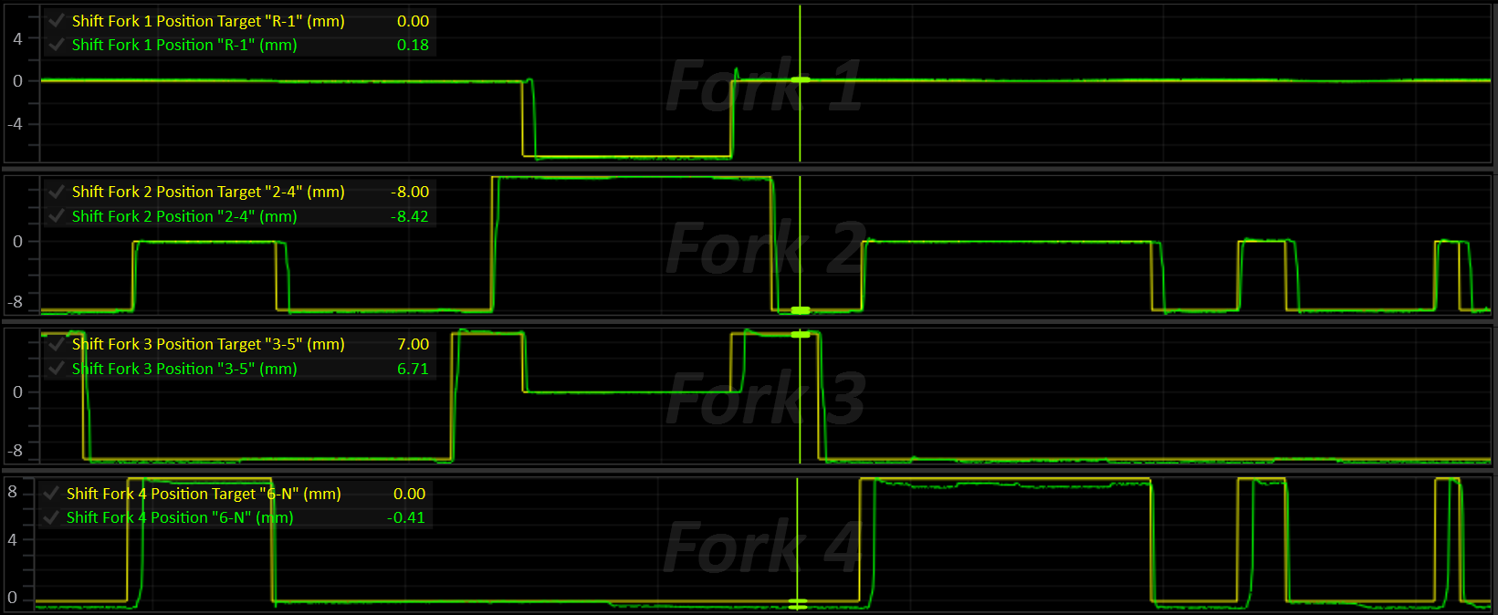
Concepts
Axes
A DCT has two input shafts (“axes”), each carrying its own clutch. While one axis is transmitting drive, the other is free to pre-select the next gear so that the shift itself is just a clutch hand-off, with no torque interruption. Every gear (including Reverse) belongs to one of these two axes:
| Clutch | Axis | Typical Gears |
|---|---|---|
| A | A | Even gears |
| B | B | Odd gears |
The active axis is whichever axis currently has a gear engaged and is transmitting drive.
The inactive axis is free to move its fork(s) to pre-select the next gear.
Clutch Axes
The TCM will always assume that the clutch and axis are a matched pair:
- Clutch A is on Axis A
- Clutch B is on Axis B
Shift Forks
A shift fork is a physical selector that can sit in one of three positions (“slots”):
| Slot | Meaning |
|---|---|
| Low | Engages the fork’s “Low” gear |
| Centre | Neutral (no gear engaged on that fork) |
| High | Engages the fork’s “High” gear |
Each fork belongs to one axis (or, for a shared Reverse fork, both axes) and is responsible for up to two gears, one on its Low side and one on its High side.
Up to 8 forks and 8 shift solenoids are supported.
While driving:
- The active axis must already have its current gear’s fork engaged (all other forks on that axis in Neutral).
- The inactive axis may have, at most, the pre-selected next gear’s fork engaged (all others in Neutral).
Only one fork is ever moved at a time. A fork on the active axis is never moved unless it’s explicitly required (e.g. a shift out of Neutral/Park), and a fork that needs to return to Neutral is always preferred over one that’s about to engage a new gear, so the way is cleared before a new gear goes in.
Fork Position Sensing
Each fork has a position sensor that is scaled and calibrated to report the fork’s measured position in millimeters. Some forks also have a secondary tracking sensor used purely for cross-checking / diagnostics.
Fork Position 1-8 inputs are configured in Input Setup.
The fork’s calibrated Low / Centre / High positions and tolerance bands are what translate this raw position into a slot (Low / Centre / High / Moving).
Fork Management
At all times the shift fork system is actively performing the following tasks:
- Each fork’s target is set:
- Active-axis forks target the current gear.
- Inactive-axis forks target the pre-selected gear.
- Everything else targets Neutral.
- Each fork’s own position/slot state is updated.
- Axis “binding” is detected if more than one fork on an axis reports being in gear at once.
- An axis fault is raised if any fork on that axis is in a position error state.
Fork Movement
- If a fork is currently moving, its movement is monitored until complete.
- Otherwise, the next fork that needs to move is found (inactive axis first, unless an active-axis move is explicitly allowed) and its movement begins.
- The physical shift solenoids are driven to move the current fork, or to hold the idle/default solenoid pattern when nothing is moving.
- If Axis Pressure Control solenoids are in use, their pressure is modulated to control fork movement speed.
- The moving fork is driven either toward its target position (default), or through a series of engagement phases when Engagement Phase Control is enabled.
Shift Procedure
- The currently engaged gear and its axis are marked as active.
- The Preselection system predicts the next shift direction (up or down) and selects the next gear on the inactive axis.
- On a shift request, the next gear’s fork is determined and pre-selected (if it’s not already) on the inactive axis.
- Once the pre-selected gear’s axis is ready (fork in target slot, no axis error), the clutch hand-off for the shift can proceed.
- After the shift completes, the new gear’s axis is marked as active, the offgoing axis is marked inactive.
- The Preselection system resumes prediction of the next shift on the newly inactive axis.
Configuration & Calibration
Shift Fork Setup (Global)
These apply to whichever fork is currently moving, regardless of which fork it is.
| Setting | Description |
|---|---|
| Shift Fork Stable Velocity (+/-) | Fork velocity threshold (± mm/s). Once a fork is inside its target slot’s tolerance band and below this velocity, its “stable” timer starts. Set to 0 to disable the velocity check (stability then depends only on being in-slot) |
| Shift Fork Stable Time | Time (ms) the fork must remain in-slot and stable before the move is considered complete |
| Engagement Phase Control | Selects how a moving fork is driven. OFF = the fork is driven toward its target position. ON = the fork is driven through a series of engagement phases, see Engagement Phase Control |
| Fork Move Idle Target | Idle speed requested from the ECU while a gear is engaged from Neutral or Park at a standstill. Engagement Phase Control only, see Standstill Engagement Aids |
Shift Fork Setup (Per-Fork)
Each fork (numbered 1–8) is independent and must be configured individually. Below, “#” stands for the fork number, eg: “Shift Fork 3 Axis”.
| Setting | Description |
|---|---|
| Shift Fork # Axis | Parent axis: Disabled / Axis A / Axis B / Both (shared, e.g. Reverse) |
| Shift Fork # Label | Free-text label for the fork (shown in the tuning software UI) |
| Shift Fork # Position L Gear | Gear engaged when the fork is in its Low slot. OFF = slot unused. |
| Shift Fork # Position H Gear | Gear engaged when the fork is in its High slot. OFF = slot unused. |
| Shift Fork # Position L | Target fork position for the Low slot (mm) |
| Shift Fork # Centre | Target fork position for the Centre (Neutral) slot (mm) |
| Shift Fork # Position H | Target fork position for the High slot (mm) |
| Shift Fork # Position L Tolerance (+/-) | Position tolerance (± band) around the Low slot (mm) |
| Shift Fork # Centre Tolerance (+/-) | Position tolerance (± band) around the Centre slot (mm) |
| Shift Fork # Position H Tolerance (+/-) | Position tolerance (± band) around the High slot (mm) |
| Shift Fork # Error Detection | Enables position error detection; bit 1 auto-clears the error once the fork returns to its target slot |
| Shift Fork # Error Auto Clear | Auto-clears the error once the fork returns to its target slot |
| Shift Fork # Error Delay | Time the fork may be out of its target slot before a position fault is raised (0–25.0 s) |
| Shift Fork # Retry Limit | Number of retries allowed after the first attempt before the fork raises a position fault. 0 = a single attempt only. See Per-Fork Position Error and Stalls and Retries |
| Shift Fork # Test | Bench/service test override: Off / Force Low, / Force Centre, / Force High. Only takes effect while the requested gear is Neutral or Park |
Notes:
- The Low and High slot positions do not need to be numerically low/high — the firmware automatically detects whether the fork’s travel is inverted (i.e. the Low position is a larger number than Centre) and corrects the shift-direction logic accordingly.
- Whichever gear ends up on the Low slot vs. High slot is purely a function of fork travel direction — set the Low/High gear assignments to match the physical gear each end of travel actually engages.
- A fork does not need both slots populated — a single-sided fork (e.g. Reverse-only) should leave the unused Low/High gear assignment at
0.
Shift Solenoid Selection
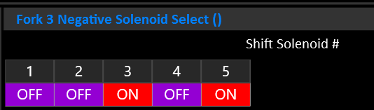
Which solenoids are energised to move a fork in a direction is controlled by the solenoid select tables.
| Table | Description |
|---|---|
| Shift Fork # Positive Solenoid Select | Selects which shift solenoid(s) (1–8) are energised to move the fork in the positive position direction (+ mm) |
| Shift Fork # Negative Solenoid Select | Selects which shift solenoid(s) (1–8) are energised to to move the fork in the negative position direction (- mm) |
| Shift Fork Idle Solenoid Select | Shift solenoid(s) held on when no fork is currently moving (idle hold pattern) |
| Default Shift Solenoid Select | Shift solenoid(s) always added to the active pattern in addition to the moving/idle pattern, when the default overlay is enabled |
| Default Shift Solenoid Enable | Enables/disables the default solenoid overlay above (non-zero = enabled) |
Important
The solenoid select table’s X-axes must be Shift Solenoid #. Multiple solenoids can be selected at once.
Per-Fork Position Sensor Calibration
Shift Fork n Position is reported in mm.
Each fork has a position sensor that can be calibrated in Input Config > Transmission Inputs > Shift Fork Positions.
It is critical that these position sensor inputs are assigned and calibrated correctly.
Fork Movement Pressure Control
While a fork is moving, its physical movement can optionally be driven by a
closed-loop position PID acting on hydraulic pressure (rather than a fixed pressure). The need for pressure control will depend on the transmission design.
When enabled, the Axis Pressure solenoids are controlled to achieve the desired pressure.
With Engagement Phase Control ON, the PID is not used. The pressure is instead set by the force of the current engagement phase, as a percentage of the maximum fork movement pressure (see Engagement Phase Control).
| Setting / Table | Description |
|---|---|
| Axis Pressure Override | Enables the axis pressure override: while set, the axis pressure of whichever axis is physically moving is driven by the fork-movement PID (or by Engagement Phase Control) instead of the normal active/inactive axis pressure targets |
| Fork Movement Pressure Base | Base (feed-forward) pressure added ahead of the PID output (Bar). Engagement Phase Control OFF only |
| Fork Movement Pressure Proportional Gain | PID proportional gain for fork movement pressure control. Engagement Phase Control OFF only |
| Fork Movement Pressure Integral Gain | PID integral gain for fork movement pressure control. Engagement Phase Control OFF only |
| Fork Movement Pressure Derivative Gain | PID derivative gain for fork movement pressure control. Engagement Phase Control OFF only |
| Axis Pressure Override Integral Min / Max | PID integral clamp (Bar). Engagement Phase Control OFF only |
| Axis Pressure Override Min / Max | Output pressure clamp (final PID output is constrained to this range) (Bar) |
| Fork Movement Pressure Max | Maximum fork movement pressure (Bar). The lower of this table and Axis Pressure Override Max is used. 0 = use Axis Pressure Override Max. With Engagement Phase Control ON, this is the pressure that equals 100% fork force |
Fork Movement Current Control
Transmissions that set fork force through the shift solenoid current rather than axis pressure (e.g. Getrag GS7) use Variable Force shift solenoids. While a solenoid is energised, its current is taken from its Shift Solenoid # Current table. The table’s axis can be chosen to suit the fork movement mode:
| Table Axis | Behaviour |
|---|---|
Active Shift Fork Position Error | High current far from the target slot, tapering as the fork arrives. Suits position control (Engagement Phase Control OFF). |
Shift Fork Force Demand | Current follows the force requested for the fork (0 - 100%), so the table becomes a force-to-current map. Required for Engagement Phase Control. |
Leave Axis Pressure Override OFF on these transmissions.
Torque Limiting During Fork Movement
Active Axis Fork Movement Torque Limit can be applied applied while a fork on the currently active axis is moving (e.g. Shifts out of Neutral/Park, where the axis being engaged is also the “active” axis).
Engagement Phase Control
Engagement Phase Control is an alternative way of driving a moving fork, built around how a synchroniser engages a gear. Instead of simply pushing the fork toward its target position, the TCM steps the fork through a series of phases (approach, synchronise, engage and settle), each with its own force. If the fork stalls, it’s backed off, rested and tried again with a little more force, rather than being held hard against the synchroniser.
This makes the biggest difference when engaging a gear from Neutral or Park at a standstill, where drag from the open clutch keeps the shaft spinning. A fork that is just pushed harder tends to sit on the synchroniser, using it as a brake against the clutch drag. Engagement Phase Control detects this, backs off and retries, and limits how hard and how long the synchroniser is worked.
It works with both pressure-actuated forks (e.g. Nissan GR6) and forks whose force is set by the shift solenoid current (e.g. Getrag GS7).
Enabling Engagement Phase Control
Set Engagement Phase Control to ON in Shift Fork Setup. The Shift Fork Engagement Phase Control folder will then appear, containing the settings and tables described below.
All fork forces are set as a percentage (0 - 100%) of the fork’s maximum force. How that percentage is turned into an output depends on how the forks are actuated:
| Fork Actuation | Setup |
|---|---|
| Axis Pressure (e.g. Nissan GR6) | Set Axis Pressure Override to ON. 100% force is the lower of Fork Movement Pressure Max and Axis Pressure Override Max. Axis Pressure Override Min sets the minimum pressure while a fork is moving. The fork movement PID tables are not used. |
| Shift Solenoid Current (e.g. Getrag GS7) | Leave Axis Pressure Override OFF. Set the Solenoid Type of the shift solenoids that move the forks to Variable Force, and set the axis of each of their Shift Solenoid # Current tables to Shift Fork Force Demand. The table then converts the requested force (%) into solenoid current. |
Axis Pressure Example
- Fork Movement Pressure Max = 18.0 Bar
- Current phase force = 40%
- Fork movement pressure = 40% of 18.0 Bar = 7.2 Bar
Fork Travel and Sync Slip
Two channels are central to how Engagement Phase Control works, and to tuning it:
Shift Fork Travelis the moving fork’s progress, from 0% at the slot it’s leaving to 100% at its target slot. Where the synchroniser sits within that travel is set by Sync Zone Start and Sync Zone End. The sync zone is shared by all forks in both directions, so it must cover every fork’s synchroniser.Shift Fork Sync Slipis the speed difference the synchroniser has to remove before the gear can engage: the speed of the target axis clutch compared to the speed the target gear would turn it at. The shaft is considered synchronised once this falls below Synchro Slip Complete Threshold. Correct clutch speed and output shaft speed readings are required.
Move Phases
Each fork move steps through the following phases, reported by Shift Fork Move Phase:
| Phase | Description |
|---|---|
| Idle | No fork is moving. |
| Approach | The fork leaves its slot at Shift Fork Approach Force and travels toward the synchroniser, until it reaches Sync Zone Start. |
| Sync | The synchroniser is loaded. Force starts at Shift Fork Sync Force Start and rises at Sync Force Ramp Rate up to the force ceiling for this attempt (Sync Force Max on the first attempt). Sync ends once the blocker ring releases and the fork passes Sync Zone End. |
| Engage | The blocker ring has released and the fork rides the dog teeth into the slot. Once the shaft is synchronised, the force changes to Shift Fork Engage Force. Until then, the force the ring released at is held, as the ring lets go slightly before the shaft is fully synchronised. If the fork is pushed back onto the ring, it returns to Sync. |
| Settle | The fork has reached its target slot and the shift solenoids are off. The move is complete once the fork has been stable in the slot for Shift Fork Stable Time (see Shift Fork Stable Velocity). If the fork bounces out of the slot, the solenoids stay off until it has come to rest, so a fork overshooting Neutral isn’t pushed back and forth between the two directions. If it comes to rest outside the slot, it’s driven back in. |
| Back Off | After a stall, the fork is pulled back toward the slot it came from by Back-Off Distance at Back-Off Force, for no longer than Back-Off Time. The fork is never pulled back past the slot it came from. |
| Rest | The shift solenoids are turned off for Retry Rest Time, allowing the synchroniser to re-centre before the next attempt. |
| Error | All attempts have been used. The fork enters its position error state, see Per-Fork Position Error. |
A fork returning to Neutral has no synchroniser to work against, so it goes straight from Approach to Engage.
Stalls and Retries
When a fork stops making progress toward its target, the TCM records why in Shift Fork Stall Type, backs the fork off, rests, then tries again.
| Stall Type | Phase | Cause |
|---|---|---|
| None | - | No stall has occurred during this move. |
| Mechanical | Approach | The fork stopped making progress for Approach Stall Time, or didn’t reach Sync Zone Start within Approach Timeout. The stall timer only starts once the fork has begun to move. |
| Blocker Ring | Sync | The blocker ring didn’t release within Sync Timeout. Or, the shaft was synchronised but the fork didn’t move for Synchro Settled Timeout with the force at its ceiling (clutch drag is holding the ring in place). |
| Equilibrium | Sync | With the force at its ceiling, Shift Fork Sync Slip didn’t fall by at least Synchro Slip Progress Validation within each Synchro Slip Progress Window. The synchroniser can’t overcome the clutch drag, so the attempt is abandoned early rather than using the synchroniser as a brake for the full Sync Timeout. |
| Dog Teeth | Engage | The fork sat, or bounced, on the dog teeth without making progress for Dog Engagement Stall Time. |
Retries work as follows:
- Each retry raises the Sync force ceiling by Sync Retry Force Step (up to 100%). The first attempt can be gentle, with force only increasing when the synchroniser needs it.
- Each fork is allowed its Shift Fork # Retry Limit retries after the first attempt. Once they have all failed, the fork enters its position error state.
- The fork’s Error Delay still limits the total time of the whole move, including every attempt.
- After a synchroniser stall (Blocker Ring or Equilibrium), the rest ends early as soon as the shaft is synchronised.
- After a Dog Teeth stall, the rest ends early as soon as the shaft has turned relative to the gear, giving the teeth a new position to engage.
Shift Fork Crash Count counts (per fork, since power up) engagements where the dog teeth went in while the shaft was still slipping above Synchro Slip Complete Threshold, i.e. the gear was forced through the synchroniser. A rising count means the Sync force ceiling is too high, or there is too much drag on the target axis.
Synchroniser Heat Protection
Repeated attempts heat the synchroniser. Shift Fork Sync Energy estimates this for each fork by accumulating slip x force x time while the synchroniser is loaded, and decays over roughly 20 seconds.
While Shift Fork Sync Energy is above Sync Energy Limit, the rest between attempts is extended from Retry Rest Time to Sync Energy Limit Cooldown. Set Sync Energy Limit to 0 to disable.
Standstill Engagement Aids
Two optional functions help engage a gear from Neutral or Park while the vehicle is stationary.
Dog Engagement Stall Clutch Pulse
If the fork stalls on the dog teeth with the shaft already synchronised, the teeth are likely sitting tip to tip. When enabled, the target axis clutch is briefly applied during the rest, at its touch point + Dog Engagement Stall Clutch Pulse Pressure for Dog Engagement Stall Clutch Pulse Time. This turns the shaft a few degrees so the teeth can line up on the next attempt.
- Only the clutch on the axis being engaged is pulsed, and only while nothing is engaged on that axis.
- It’s never used after a synchroniser stall.
Shift Fork Clutch Pulse Statusis ON while the pulse is applied, and the clutch status reportsOn - Shift Fork Clutch Pulse.
Fork Move Idle Target (Shift Fork Setup)
A lower engine idle speed means less clutch drag for the synchroniser to overcome. While a gear is being engaged from Neutral or Park at a standstill, the Fork Move Idle Target is output on Shift Fork Idle Speed Request (0 at all other times). To use it, transmit Shift Fork Idle Speed Request to the ECU in a CAN message and configure the ECU to use it as its idle target. Set to 0 to disable.
Engagement Phase Settings
Found in Shift Fork Engagement Phase Control > Shift Fork Engagement Phase Setup.
| Setting | Description |
|---|---|
| Approach Stall Time | Time the fork may go without making progress during Approach before a Mechanical stall is declared. The timer only starts once the fork has begun to move, so it doesn’t need to allow for break-away (ms) |
| Approach Timeout | Approach must reach Sync Zone Start within this time, or a Mechanical stall is declared (ms) |
| Sync Zone Start | Fork travel at which the fork reaches the blocker ring and the Sync phase begins (0% = slot being left, 100% = target slot). Set comfortably below the travel where forks are seen to stall on the synchroniser (%) |
| Sync Zone End | Fork travel at which the blocker ring is considered released and the Engage phase begins. Set above the highest synchroniser stall position, and below where the dog teeth are reached (%) |
| Sync Timeout | Longest time the synchroniser is loaded in one attempt before the fork backs off. Limits synchroniser heating (ms) |
| Sync Force Ramp Rate | Rate the force rises from Shift Fork Sync Force Start up to the force ceiling. A slow ramp spends longer at a force where the synchroniser can work. A fast ramp reaches the ceiling quickly and is more likely to push through the blocker ring before the shaft is synchronised (%/s) |
| Sync Force Max | Force ceiling for the first attempt. Should be below the force that pushes the fork through the blocker ring while the shaft is still spinning (%) |
| Sync Retry Force Step | Added to the force ceiling on each retry, up to 100% (%) |
| Synchro Slip Progress Validation | With the force at its ceiling, Shift Fork Sync Slip must fall by at least this much every Synchro Slip Progress Window, or an Equilibrium stall is declared (RPM) |
| Synchro Slip Progress Window | Time window over which slip progress is checked (ms) |
| Synchro Slip Complete Threshold | Shift Fork Sync Slip below which the shaft is considered synchronised (RPM) |
| Synchro Settled Timeout | If the shaft is synchronised with the force at its ceiling, but the fork isn’t moving for this long, a Blocker Ring stall is declared so the ring can re-centre (ms) |
| Sync Energy Limit | Synchroniser heat limit, compared with Shift Fork Sync Energy. 0 = disabled |
| Sync Energy Limit Cooldown | Rest time used instead of Retry Rest Time while the synchroniser is over its Sync Energy Limit (ms) |
| Dog Engagement Stall Time | Time the fork may go without making progress on the dog teeth during Engage before it backs off (ms) |
| Back-Off Distance | How far the fork is pulled back toward the slot it came from after a stall. Enough to fully unload the blocker ring or clear the dog teeth (mm) |
| Back-Off Time | Longest time the back off is driven if Back-Off Distance isn’t reached (ms) |
| Back-Off Force | Force used to pull the fork back after a stall. It only needs to unload the ring or lift the fork off the dog teeth, not move quickly (%) |
| Retry Rest Time | Time the shift solenoids are off between attempts (ms) |
| Dog Engagement Stall Clutch Pulse | Enables the dog stall clutch pulse, see Standstill Engagement Aids |
| Dog Engagement Stall Clutch Pulse Pressure | Pressure above the clutch touch point applied during the pulse. Just enough to turn an unloaded shaft (Bar) |
| Dog Engagement Stall Clutch Pulse Time | Length of the pulse. The rest between attempts is held until the pulse has finished (ms) |
Force Tables:
| Table | Description |
|---|---|
| Shift Fork Approach Force | Force from leaving the slot until the fork reaches Sync Zone Start. Enough to move the fork briskly, without throwing it at the blocker ring. Too low and the fork won’t break away, resulting in a Mechanical stall (%) |
| Shift Fork Sync Force Start | Force when the fork first loads the blocker ring. The synchroniser works best at a moderate force, so starting low gives it a chance to synchronise the shaft before the force ramps up. Consider spanning this table against Output Shaft Speed, so pre-selection while driving starts closer to the ceiling and only standstill engagements start gently (%) |
| Shift Fork Engage Force | Force used to push the fork through the dog teeth into the slot once the shaft is synchronised. Too low and the fork will stall on the dog teeth. Too high and it will slam into the slot (%) |
Tuning Engagement Phase Control
Complete the standard Calibration Procedure first. Fork travel is measured between the calibrated slot positions, so these must be accurate.
Check
Shift Fork Sync Slipreads sensibly during a fork movement. It relies on correct clutch speed and output shaft speed readings.Set up the force range for the fork actuation type, see Enabling Engagement Phase Control.
Enable Engagement Phase Control and log a number of engagements from Neutral at a standstill, as well as pre-selections while driving. Log
Shift Fork Move Phase,Shift Fork Stall Type,Shift Fork Move Attempt,Shift Fork Travel,Shift Fork Sync Slip,Shift Fork Force DemandandShift Fork Crash Count, along with each fork’s Position.Set the sync zone from
Shift Fork Travelat the point where each fork stalls on the synchroniser. Sync Zone Start should be below the lowest stall point, and Sync Zone End above the highest.Set Shift Fork Sync Force Start low enough that the synchroniser has a chance to work before the force ramps up to its ceiling. Only then raise Sync Force Max if forks still fail to engage.
Watch
Shift Fork Crash Count. A rising count means the force ceiling is overpowering the blocker ring rather than letting the synchroniser work. The fix is less force or less drag (e.g. a lower idle with Fork Move Idle Target), not more force.Review stall types at a standstill. Repeated Equilibrium stalls mean clutch drag is too high for the synchroniser to overcome, so reduce drag rather than adding force. Repeated Dog Teeth stalls with the shaft synchronised can be helped by the Dog Engagement Stall Clutch Pulse.
Set each fork’s Retry Limit and Error Delay last, once engagement is reliable.
Errors & Diagnostics
Per-Fork Position Error
If a fork’s error-detection is enabled, a fork that fails to reach its target slot within its Error Delay (or whose position sensor reports a fault) raises a Fork # Movement fault and enters an internal error state.
From the error state, the firmware automatically retries the move, up to the fork’s Retry Limit, 1 second apart. With Engagement Phase Control ON, retries are made within the move itself (see Stalls and Retries), so there are no further automatic retries once the fork has entered the error state. If Error Auto Clear is enabled, the error clears automatically once the fork successfully reaches its target slot again (and the position sensor is healthy) — this is normally only allowed to happen when the fork’s target is Centre (Neutral), so a fork always has to prove it can get back to a safe state before being trusted again.
Using the tuning software’s “Clear All Codes” action also resets every fork’s retry count, in addition to clearing the fault codes themselves — so a fork that had exhausted its retries gets a fresh set of attempts on its next movement, rather than immediately re-latching into a fault.
Axis errors
Each axis is also monitored as a whole:
| Fault | Cause |
|---|---|
| Axis A Bound / Axis B Bound | More than one fork on that axis reports being in gear simultaneously — i.e. the axis is mechanically bound between two gears |
| Axis A Fault / Axis B Fault | At least one fork on that axis is in a position error state |
While an axis is in fault, no fork on that axis will be moved until the fault clears.
Related channels for diagnosis
See Runtime Channels for the full list. Each fork’s Status and Position Error, and the Moving Shift Fork channel, are usually the first things worth logging when diagnosing a shift fork issue.
Runtime Channels
Per-Fork Channels (# = fork number, 1–8):
| Channel | Description |
|---|---|
| Shift Fork # Position | Measured fork position, mm |
| Shift Fork # Position Target | Target fork position, mm |
| Shift Fork # Position Error | Position error (target − measured), mm |
| Shift Fork # Velocity | Measured fork velocity, mm/s |
| Shift Fork # Status | see Shift Fork Status enumeration |
| Shift Fork # Tracking | Secondary/tracking position sensor reading (diagnostic only) |
System-Wide Channels:
| Channel | Description |
|---|---|
| Selected Gear A | Gear currently engaged on Axis A |
| Selected Gear B | Gear currently engaged on Axis B |
| Active Gear Shift Fork | Fork responsible for the currently active (engaged) gear |
| Preselected Gear Shift Fork | Fork responsible for the pre-selected next gear |
| Moving Shift Fork | Fork currently moving |
| Active Shift Fork Position | Position of whichever fork is currently moving |
| Active Shift Fork Position Target | Target position of whichever fork is currently moving |
| Active Shift Fork Position Error | Position error of whichever fork is currently moving |
| Active Axis Pressure Target | Active axis clutch pressure target, Bar |
| Inactive Axis Pressure Target | Inactive axis clutch pressure target, Bar |
| Active Axis Fork Movement Torque Limit | Torque limit currently applied due to active-axis fork movement |
| Shift Fork Movement Pressure | Fork movement pressure demand output, Bar |
| Shift Fork Movement Pressure Base | Fork movement pressure base/feed-forward term |
| Shift Fork Movement Pressure P Gain | Fork movement pressure PID proportional term |
| Shift Fork Movement Pressure I Gain | Fork movement pressure PID integral term |
| Shift Fork Movement Pressure D Gain | Fork movement pressure PID derivative term |
| Shift Fork Force Demand | Force requested for the moving fork, % of maximum. Also reported with Engagement Phase Control OFF while Axis Pressure Override is ON |
Engagement Phase Control Channels:
| Channel | Description |
|---|---|
| Shift Fork Move Phase | Phase of the moving fork, see Shift Fork Move Phase enumeration |
| Shift Fork Stall Type | Reason for the most recent back off, see Shift Fork Stall Type enumeration and Stalls and Retries |
| Shift Fork Move Attempt | Attempt number of the current move, 1 = first attempt. 0 when no fork is moving |
| Shift Fork Phase Time | Time spent in the current phase, ms |
| Shift Fork Travel | Fork progress from the slot it’s leaving (0%) to its target slot (100%) |
| Shift Fork Sync Slip | Speed difference the synchroniser has to remove, RPM. 0 for a return to Neutral |
| Shift Fork Crash Count | Number of engagements of the moving fork, since power up, where the dog teeth went in with the shaft still slipping |
| Shift Fork Sync Energy | Heat estimate for the moving fork’s synchroniser, compared with Sync Energy Limit |
| Shift Fork Clutch Pulse Status | ON while the Dog Engagement Stall Clutch Pulse is applied |
| Shift Fork Idle Speed Request | Idle speed requested from the ECU during a standstill engagement, RPM. 0 when not requested |
Calibration Procedure
Enable each fork — set the Axis setting for every physical fork fitted (Axis A, B, or Both for a shared Reverse fork). Leave unused fork slots OFF.
Wire up and calibrate position sensors first, via the standard analog input mapping/translation tools, so that each fork’s Position channel reads a correctly-scaled value (mm) across the whole range of travel.
Set tolerance bands (Low/Centre/High Tolerance) tight enough to confirm the dog teeth/synchro are actually engaged, but loose enough to tolerate normal sensor noise and mechanical play.
Assign gears to each slot via Position L Gear / Position H Gear. You may have to put some educated guesses into the positions initially.
Assign shift solenoids per fork (Positive/Negative Solenoid Select) and confirm direction — command a move with Test mode and verify the fork moves the correct way and its Status reports moving in the expected direction, then settles into the correct slot.
Set idle/default solenoid patterns (Idle Solenoid Select, Default Select / Enable) as required by the actuator hardware.
Find and record the three slot positions for each fork with the vehicle safely supported and the driveline free to move by hand, or using the fork’s Test setting to command it to each slot in turn (only works while the requested gear is Neutral or Park):
- Force to Low, record the settled Position reading into Position L.
- Force to Centre, record Centre position.
- Force to High, record Position H.
- Set Test back to Off when done.
Tune move-complete detection — Stable Velocity and Stable Time — so a fork isn’t reported as “done” while still settling, but without adding unnecessary delay to every shift.
Tune fork movement pressure (if using closed-loop pressure control): set the Movement Pressure Base and PID gains, and the Pressure Override Min/Max and Integral Min/Max clamps, then set Axis Pressure Override to ON if pressure-based fork actuation is desired instead of fixed axis pressure targets. If using Engagement Phase Control, follow Tuning Engagement Phase Control instead.
Set error detection last, once movement is proven reliable. Set each fork’s Error detect / Auto-Clear and Error Delay, generous enough to allow for normal shift timing but tight enough to catch a stuck fork.
Verify full shift sequences in all gears, both directions, watching the Active Gear Shift Fork, Preselected Gear Shift Fork and Moving Shift Fork channels. Watch each fork’s Status & Position, for consistent, movement and engagement. Confirm no Axis Bound/Axis Fault faults occur across the full gear range.