Subsections of Wiring
Ethernet Wiring
The TCM uses 10/100Base-T Ethernet communications. It only requires 4 wires (2 pairs) to operate.
| Signal | MTC Pin | RJ45 Pin | Colour |
|---|---|---|---|
| Rx+ | C20 | 3 | Orange/White |
| Rx- | C21 | 6 | Orange |
| Tx+ | C22 | 1 | Green/White |
| Tx- | C23 | 2 | Green |
No special ethernet configuration is required. TMtune will detect the device using an IPv6 Link Local Address.
Hall Effect Inputs
Dedicated 2-Wire Hall Effect Inputs
The TCM contains 4 dedicated 2-wire hall effect inputs. These inputs are suitable for speed sensors found in many transmissions and ABS systems.
Unlike normal digital inputs, they actually provide the sensor with a regulated current source at the system’s battery voltage. When the sensing target passes the sensor, the current draw from the sensor will change. This change in current is used to determine an “edge”.
| Input | TCM Pin |
|---|---|
| Hall Input 1 | C10 |
| Hall Input 2 | C11 |
| Hall Input 3 | C12 |
| Hall Input 4 | C13 |
Info
The power supply for the hall inputs is sourced from Aux 1-4 Supply (Pin C2).
Each Hall Input outputs the following data:
- Frequency (0.5 – 20 KHz)
- Duty Cylce (%)
- Period (ms)
- Pulse Width (ms)
Known Applications
- BMW / Getrag GS7 DCT Input Shaft Speed & Clutch Speeds
- Toyota GT86 ABS Sensors
Wiring
| Sensor Pin | TCM Pin |
|---|---|
| Sensor Pin 1 | Hall Input 1-4 |
| Sensor Pin 2 | GND |
Note: The sensor may be grounded remotely.
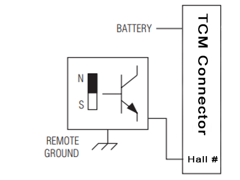
There’s no requirement to set arming thresholds or pulldown resistors.
Hall Inputs on DI 1-8
It’s possible to use 2-wire hall effect sensors on DI-18, and in some cases this is required.
The principle is similar but the wiring is very different. The sensor needs to be supplied with a regulated voltage (eg: 8.0V) and the signal wire goes to a digital input where it’s grounded through the internal pulldown resistor. This creates a measurable voltage that the TCM can use to measure rising and falling edges.
Known Applications
- ZF 8HP Input Shaft Speed & Output Shaft Speed
Wiring
| Sensor Pin | TCM Pin |
|---|---|
| Sensor Pin 1 | 8.0V |
| Sensor Pin 2 | DI 1-8 (Pulldown ON) |
Important
The input pin’s pulldown resistor must be enabled and the arming thresholds set correctly.
Arming Thresholds
The high and low arming thresholds must be set correctly to detect the speed signal. You can watch the raw voltage of the digital input pin to determine the thresholds.
- The low threshold must be ABOVE the sensor voltage at rest.
- The high threshold must be BELOW the maximum voltage when the sensor is active.
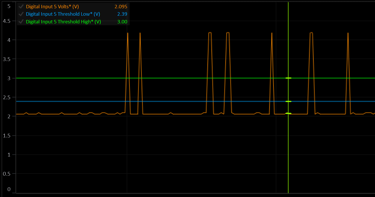
: If the voltage is near 0V or near the 8V supply, the sensor is probably wired wrong.
Power Supply
This document outlines the correct wiring of the TCM’s power supplies and power outputs.
Power Supplies
The TCM can be used in 12V or 24V systems with a nominal supply voltage of 9-32V.
All power supply pins are protected against reverse polarity, over current, over voltage, over temperature, transients and load dumps.
Voltages are clamped internally to 35V.
Important
All power supply pins must be wired, even if you’re not using them. Eg: Don’t skip the Auxiliary Supply inputs because you don’t need to use the auxiliary outputs.
Battery Hot Supply
| Pin | Voltage | Current |
|---|---|---|
| C1 | 9-32V | < 1A |
Warning
This pin must be powered at all times to allow the TCM to control it’s own power supply. Failure to do so may result in data logging memory being corrupted.
When more than ~3.5V is present on the Ignition Switch pin (C6), the internal circuitry will turn on the circuits connected to pin C1 and the TCM will power up.
Once the TCM is booted, the CPU will latch the internal power switch ON. In this state, if the voltage on the Ignition Switch pin drops to 0, the TCM will remain on until the CPU completes any pending critical tasks and disables the internal power latch.
When the TCM is off, this pin does NOT draw any current.
Ignition Switch
| Pin | Voltage | Current |
|---|---|---|
| C6 | 9-32V | < 3mA |
Info
The Ignition Switch pin does NOT supply any power to the device. Without connecting the Battery Hot Supply pin (C1), the TCM will not power up.
The ignitions switch serves only to enable the internal power switch connected to pin C1. It’s voltage is monitored by the TCM at all times and the data is available to the user.
Auxiliary Supplies
| Pin | Voltage | Current |
|---|---|---|
| C2 | 9-32V | 15A max, Application Specific |
| C3 | 9-32V | 15A max, Application Specific |
Pins C2 and C3 supply the half bridge drivers on Aux Output 1-8. The current draw of these inputs is determined by the total high side current of the Auxiliary outputs.
The auxiliary outputs are split into 2 banks of 4: 1-4 and 5-8. The total continuous high side current of a single bank should not exceed 15A for an extended period of time.
Auxiliary Supply pins can be supplied with constant or switched power, as long as they are always powered when the ignition switch is on. The TCM will only turn them on when the ignition switch is on.
Solenoid Supplies
| Pin | Voltage | Current |
|---|---|---|
| C4 | 9-32V | 15A max, Application Specific |
| C5 | 9-32V | 15A max, Application Specific |
Pins C4 and C5 supply the Solenoid power output pins (B30-B33) as well as the flywheel diodes and voltage monitors of the solenoid drivers.
Solenoid Supply pins can be supplied with constant or switched power, as long as they are always powered when the ignition switch is on. The TCM will only turn them on when the Ignition switch is on.
Solenoid Power Outputs
| Pin | Solenoids | Continuous Current |
|---|---|---|
| B30 | 1-4 | 7.5A |
| B31 | 5-8 | 7.5A |
| B32 | 9-12 | 7.5A |
| B33 | 13-16 | 7.5A |
The 4 Solenoid Power Supply Output pins are intended to supply the high side of the solenoids driven by any of the 16 Solenoid Output pins.
All supply outputs are protected against reverse polarity, short to ground, over current, over voltage, over temperature.
Ideally, you should supply the solenoids with their respective linked output. This means that in the event of a critical fault, the TCM can shut down the supply to the problem solenoid bank. Some applications will not be flexible enough to allow this. Best judgement should be used to make the system as robust as possible.
Example: ZF 8HP: There is only 1 solenoid supply pin for 9 solenoids. You can join two or more output pins to increase to total current capacity of the supply.
Note: During normal operation in a typical transmission, not all solenoids are on at the same time and not all solenoids will be commanding maximum current.